ICS XMC-A825-16 User manual

XMC-A825-16 ARINC-825 16 Channel XMC / CANFlight-16 User's Manual REV C
Document: TP2216-901_Users_Manual.pdf Page 1 of 39 © Innovative Control Systems
Project: TP2216-901 Author: K. Jacobson Date: 11.05.2019 Rev.: C

XMC-A825-16 ARINC-825 16 Channel XMC / CANFlight-16 User's Manual REV C
Document: TP2216-901_Users_Manual.pdf Page 2 of 39 © Innovative Control Systems
Project: TP2216-901 Author: K. Jacobson Date: 11.05.2019 Rev.: C
Table of Contents
1 Introduction ................................................................................................................................................... 5
2 Environmental Specifications........................................................................................................................ 8
3 Front Panel Connectors and Indicators ........................................................................................................ 9
3.1 Gigabit Ethernet Connection............................................................................................................... 11
3.2 CAN I/O Connector (VHD-68)............................................................................................................. 12
4 XMC-A825-16 ON Board I/O Connectors...................................................................................................14
4.1 On Board µSDXC card connector ...................................................................................................... 14
4.2 On Board CAN I/O P1......................................................................................................................... 15
4.3 On Board CAN I/O P2......................................................................................................................... 16
4.4 On Board Pn5 XMC Connector .......................................................................................................... 17
5 CANFLIGHT-16 Stand Alone 16-Channel Interface................................................................................... 18
5.1 CANFlight-16 9-36VDC Power Connectors........................................................................................ 19
6 TP9060 Optional CAN-FD IO PANEL Connectors ..................................................................................... 20
7 Ethernet Interface ....................................................................................................................................... 23
8 XMC-A825-16 Configuration....................................................................................................................... 23
9 XMC-A825-16 Firmware Upgrades ............................................................................................................ 32
10 XMC-A825-16 Application Programmer's Interface................................................................................ 33
10.1 Pmc825StartInterface()....................................................................................................................... 34
10.2 Pmc825StopInterface()....................................................................................................................... 34
10.3 Pmc825RawCanRead()...................................................................................................................... 34
10.4 Pmc825RawCanWrite() ...................................................................................................................... 35
10.5 Pmc825CanAerospaceRead()............................................................................................................ 35
10.6 Pmc825CanAerospaceWrite() ............................................................................................................ 35
10.7 Pmc825Arinc825Read() ..................................................................................................................... 36
10.8 Pmc825Arinc825Write()...................................................................................................................... 36
10.9 Pmc825CtrlRead() .............................................................................................................................. 36
10.10 Pmc825CtrlWrite() .......................................................................................................................... 37
11 The XCT Toolbox.................................................................................................................................... 38
12 XMC-A825-16 Supplier List .................................................................................................................... 39
13 ARINC825/CANaerospace Websites ..................................................................................................... 39

XMC-A825-16 ARINC-825 16 Channel XMC / CANFlight-16 User's Manual REV C
Document: TP2216-901_Users_Manual.pdf Page 3 of 39 © Innovative Control Systems
Project: TP2216-901 Author: K. Jacobson Date: 11.05.2019 Rev.: C
Figure 1-1 XMC-A825-16 Hardware ................................................................................................................... 5
Figure 1-2 XMC-A825-16 Block Diagram .......................................................................................................... 7
Figure 2-1 XMC-A825-16 Front Panel................................................................................................................ 9
Figure 2-2 Gigabit Ethernet Connector layout............................................................................................... 11
Figure 3-1 Typical µSDHC Card....................................................................................................................... 14
Figure 3-2 µSDHC Pinout ................................................................................................................................. 14
Figure 4-1 CANFLIGHT-16 configuration of XMC-A825-16........................................................................... 18
Figure 4-2 CANFlight-16 Power Connectors.................................................................................................. 19
Figure 5-1 CAN-FD IO PANEL.......................................................................................................................... 20
Figure 5-2 Connectors P1 to P16 CAN D-Sub Male Pinout ............................................................................... 20
Figure 5-3 Debug P17 D-Sub Male Connector Pinout .......................................................................................21
Figure 5-4 J2 IRIG-B BNC Jack ....................................................................................................................... 22
Figure 5-5 J1 VHD-68 Connector..................................................................................................................... 22
Table 1: XMC-A825-16 Front Panel Elements ................................................................................................... 10
Table 2: RJ-45 Connector Signal Definition ....................................................................................................... 11
Table 3 VHD-68 Front Panel I/O Pinout........................................................................................................... 13
Table 4: µSDHC Connector Signal Definition..................................................................................................... 14
Table 5: P1 to P16 CAN D-Sub Male Connector Pinout ....................................................................................20
Table 6: P17 D-Sub Male Connector Signal Definition ...................................................................................... 21
Table 7: XMC-A825-16 Configuration File Tags ................................................................................................ 26
Table 8: Local and Remote Port Numbers for Communication with XCT (Default Settings) ............................. 31

XMC-A825-16 ARINC-825 16 Channel XMC / CANFlight-16 User's Manual REV C
Document: TP2216-901_Users_Manual.pdf Page 4 of 39 © Innovative Control Systems
Project: TP2216-901 Author: K. Jacobson Date: 11.05.2019 Rev.: C

XMC-A825-16 ARINC-825 16 Channel XMC / CANFlight-16 User's Manual REV C
Document: TP2216-901_Users_Manual.pdf Page 5 of 39 © Innovative Control Systems
Project: TP2216-901 Author: K. Jacobson Date: 11.05.2019 Rev.: C
1 Introduction
The XMC-A825-16 interface system offers 16 electrically isolated CAN 2.0B interfaces according to ISO
11898, an IRIG-B time code input and a 10/100/1000 BaseT Ethernet interface. To minimize CPU load on host
computers, the XMC-A825-16 uses an onboard Xilinx Artix 7 FPGA with Five 128 MHz Microblaze processors
and 24 MByte SRAM to process and store CAN messages. The CAN bus interfaces are accessible via a VHD-
68 front panel connector as well as two 40-pin rectangular on-board connectors behind the VHD-68 connector.
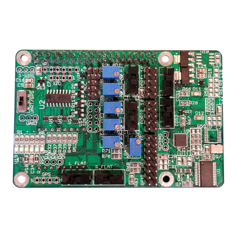
Figure 1-1 XMC-A825-16 Hardware
The XMC-A825-16 features are:
•Laptop-ready, 5 Processor Based Embedded Realtime Control System for Ground and Airborne Use
•Sixteen (16) isolated, fully independent Controller Area Network (ISO 11898), ARINC825 and
CANaerospace protocol compliant interfaces
•Integrated µSDHC card-based Flight Data Recording Option available
•IRIG-B Time Code Input for High Precision Data Synchronization
•Auto-negotiating 10/100/1000 BaseT Ethernet interface with CANaerospace over Ethernet (CoE) and
ARINC825 over Ethernet (A825oE) protocol and Application Programmer Interface (API)
•IEEE 802.11 Wireless LAN Option with CANaerospace over Wireless (CoW) and ARINC825 over Wireless
(A825oW) protocol available
•Frontpanel Activity LEDs for CAN and Ethernet
•Power Supply 5V through XMC interface or through ICS Stand Alone Aircraft power supply. Aircraft Power
(9-36VDC)
•Mechanical Dimensions 149mm L x 74mm W x 47mm H
•CAN/ARINC825/CANaerospace toolbox for Linux, MacOS and Windows
•Custom Software and FPGA firmware Options available on request

XMC-A825-16 ARINC-825 16 Channel XMC / CANFlight-16 User's Manual REV C
Document: TP2216-901_Users_Manual.pdf Page 6 of 39 © Innovative Control Systems
Project: TP2216-901 Author: K. Jacobson Date: 11.05.2019 Rev.: C
The XMC-A825-16 is a specific purpose embedded computer system that utilizes its processing power to relief
external computer systems from the tasks of transmitting, receiving, buffering and pre/postprocessing low,
medium or high-speed CAN, CANaerospace and ARINC 825 messages. It can handle up to 100% bus load at
the maximum CAN data rate of 1MBit/s on both channels without data loss. The driver software provides an
easy-to-handle function call interface for CAN bus message transmission and reception including support for
the CANaerospace and ARINC 825 higher layer protocols. The XMC-A825-16 software consists of host
drivers for various operating systems and platforms, sample “C” source code and the XCT toolbox connected
to the XMC-A825-16 via Ethernet/UDP/IP. The Illustration below shows the XMC-A825-16 block diagram.
The XMC-A825-16 CAN 2.0B interfaces are implemented with licensed Bosch M_CAN controller IP cores to
ensure compatibility with the Bosch CAN standard and to allow precise hardware timing and control over the
transmission and reception of CAN/ARINC825/CANaerospace messages. The Xilinx FPGA and the XMC-
A825-16 firmware provide local buffering and 60ns time stamp resolution for all CAN messages and
implement ARINC825/CANaerospace specific protocol functions. High precision time synchronization of CAN
messages is accomplished through an IRIG-B time code input providing 1µs resolution. An integrated µSDHC
interface is used for data acquisition storage, system configuration information and firmware upgrades.
XMC-A825-16 can be integrated into a rugged aluminum box and powered from 9-36 VDC allowing it to run
from standard 14V or 28V DC aircraft power buses according to the EN2282 specification. In this configuration
it is called a CANFlight-16 The power input lines are protected against transient overvoltage and
electromagnetic interference. The total power consumption of a XMC-A825-16 unit is less than 5Watts. The
CAN and Ethernet interfaces are serviced by different processors so that all interfaces may be used at the
same time without any loss of data. XMC-A825-16 units may be connected to host computers using
CANaerospace/ARINC825 and the auto-negotiating 10/100/1000 BaseT Ethernet interface with the CAN over
Ethernet protocol standard developed by Stock Flight Systems. The Wireless LAN (IEEE 802.11) option for
CANFlight-16 version provides an integrated DHCP server and a web-based configuration interface. The
µSDHC card slot accepts cards with sizes up to 128 GBytes.
XMC-A825-16 units can work as either standalone systems or as intelligent nodes within simple or complex
CAN, CANaerospace and ARINC825 networks, They are interoperable with the Dual Channel CANFlight and
the 4-channel PowerNECS in any combinations on the same network. The interface between XMC-A825-16
and host computer applications via Ethernet/UPD/IP, either wired or wireless, is realized through a
corresponding Application Programming Interface (API) for a variety of operating systems including Linux,
Solaris, MacOS, Windows and VxWorks.

XMC-A825-16 ARINC-825 16 Channel XMC / CANFlight-16 User's Manual REV C
Document: TP2216-901_Users_Manual.pdf Page 7 of 39 © Innovative Control Systems
Project: TP2216-901 Author: K. Jacobson Date: 11.05.2019 Rev.: C
Figure 1-2 XMC-A825-16 Block Diagram

XMC-A825-16 ARINC-825 16 Channel XMC / CANFlight-16 User's Manual REV C
Document: TP2216-901_Users_Manual.pdf Page 8 of 39 © Innovative Control Systems
Project: TP2216-901 Author: K. Jacobson Date: 11.05.2019 Rev.: C
2 Environmental Specifications
•Passively Cooled. No moving parts, -40°C to +70°C (+85°C with airflow)
•Weight: 100 grams or less in standard configuration (XMC Card Only)
•Power Consumption < 10W all 16-channels driven
•155 mm L x 75mm W x 13.4mm H (Overall Dimensions XMC Card)
•Operating Altitude Less than 25.000ft (7600m)
•Humidity 95% or less, non-condensing
•5V or 12V power from VPWR Pins of XMC Card Connector (<10 watts)
•Vibration, surpasses requirements of DO-160 Category S

XMC-A825-16 ARINC-825 16 Channel XMC / CANFlight-16 User's Manual REV C
Document: TP2216-901_Users_Manual.pdf Page 9 of 39 © Innovative Control Systems
Project: TP2216-901 Author: K. Jacobson Date: 11.05.2019 Rev.: C
3 Front Panel Connectors and Indicators
The XMC-A825-16 front panel is shown in Figure 3-1 the usage of the various connectors and LEDs is
described in Table. Note that the CAN channels are numbered CH1-CH16 for indicators on the Optional
TP9060 I/O Panel and connectors but are referred to as channels 0 through 15 for all software functions
including the configuration file (section 8 and 10 ).
Figure 3-1 XMC-A825-16 Front Panel

XMC-A825-16 ARINC-825 16 Channel XMC / CANFlight-16 User's Manual REV C
Document: TP2216-901_Users_Manual.pdf Page 10 of 39 © Innovative Control Systems
Project: TP2216-901 Author: K. Jacobson Date: 11.05.2019 Rev.: C
Table 1: XMC-A825-16 Front Panel Elements
The CAN activity LEDs located on the front panel (TX, RX) indicate if a CAN channel transmits and/or receives
CAN messages. Every CAN channels has a dedicated RX/TX activity LED which flashes once for every
transmitted/received message or continuously at a rate of 2Hz in case of a steady message flow.
If the RX activity LED of a particular CAN channel stays dark in an active network, the physical interface
correctness of all network nodes including the used baud rates, sample points and termination resistors should
be verified.
XMC-A825-16 Front Panel
Element
Description
ETHERNET Connector Standard RJ-45 connector used for the interface between XMC-
A825-16 and other computer systems using 10/100/1000 BaseT
Ethernet. The XMC-A825-16 Ethernet supports auto-negotiating of
the bus speed as well as support for ICMP echo requests so that
XMC-A825-16 systems respond to “ping” commands over the
network. This connector is only used when the on-
board Intel Gigabit
Ethernet Controller is not enabled. To use this interface, the option
PCI=0 must be set in the configuration file “XMC_A825.CFG” on the
micro SD card installed. See the Section entitled XMC-A825-16
Configuration
Status LED S1 Bicolor LED which is illuminated in red during the start of the XMC-
A825-16
firmware or in case of an internal system failure. This LED
flashes green during normal operation (with 90% on-
time versus 10%
off-time).
Status LED S2 Bicolor LED which is illuminated in red during the start of the XMC-
A825-
16 firmware or in case of an internal system failure. This LED
flashes green during normal operation (with 90% on-
time versus 10%
off-time).

XMC-A825-16 ARINC-825 16 Channel XMC / CANFlight-16 User's Manual REV C
Document: TP2216-901_Users_Manual.pdf Page 11 of 39 © Innovative Control Systems
Project: TP2216-901 Author: K. Jacobson Date: 11.05.2019 Rev.: C
3.1 Gigabit Ethernet Connection
The XMC-A825-16 ETHERNET Connector has a pinout according to the established RJ-45 standard as
shown in Figure Illustration. This connector also contains two Status LEDS which indicate the negotiated
Ethernet data rate and interface transmit activity.
This connector is only used when the on-board Intel Gigabit Ethernet Controller is not enabled. To use this
interface, the option PCI=0 must be set in the configuration file “XMC_A825.CFG” on the micro SD card
installed. See the Section entitled XMC-A825-16 Configuration
Figure 3-2 Gigabit Ethernet Connector layout
Table shows the corresponding Ethernet signal assignment for the RJ-45 connector.
Pin
Signal Name
Signal Description
1 TX+ Transmit Data +
2 TX- Transmit Data -
3 RX+ Receive Data +
4 N.C. Not Connected
5 N.C. Not Connected
6 RX- Receive Data -
7 N.C. Not Connected
8 N.C. Not Connected
Table 2: RJ-45 Connector Signal Definition
1 2 3 4 5 6 7 8
Speed LED
Green: 100 Mbit/s
Tx modulates
Speed LED
Amber: 1 Gig bit/s
Tx modulates

XMC-A825-16 ARINC-825 16 Channel XMC / CANFlight-16 User's Manual REV C
Document: TP2216-901_Users_Manual.pdf Page 12 of 39 © Innovative Control Systems
Project: TP2216-901 Author: K. Jacobson Date: 11.05.2019 Rev.: C
3.2 CAN I/O Connector (VHD-68)
Name
VHD
68 Pin Description Notes
CAN HI CH0 1 CAN 0 High No on board Terminations
CAN LO CH0 5 CAN 0 Low No on board Terminations
CAN HI CH1 2 CAN 1 High No on board Terminations
CAN LO CH1 6 CAN 1 Low No on board Terminations
CAN HI CH2 CAN 2 High No on board Terminations
CAN LO CH2 7 CAN 2 Low No on board Terminations
CAN HI CH
4
CAN High
No on board Terminations
CAN LO CH 8 CAN Low No on board Terminations
CAN HI CH4
5
CAN 4 High
No on board Terminations
CAN LO CH4 9 CAN 4 Low No on board Terminations
CAN HI CH5 6 CAN 5 High No on board Terminations
CAN LO CH5 40 CAN 5 Low No on board Terminations
CAN HI CH6 7 CAN 6 High No on board Terminations
CAN LO CH6 41 CAN 6 Low No on board Terminations
CAN HI CH7 8 CAN 7 High No on board Terminations
CAN LO CH7
42
CAN 7 Low
No on board Terminations
CAN HI CH8 26 CAN 8 High No on board Terminations
CAN LO CH8 60 CAN 8 Low No on board Terminations
CAN HI CH9 27 CAN 9 High No on board Terminations
CAN LO CH9 61 CAN 9 Low No on board Terminations
CAN HI CH10 28 CAN 10 High No on board Terminations
CAN LO CH10 62 CAN 10 Low No on board Terminations
CAN HI CH11 29 CAN 11 High No on board Terminations
CAN LO CH11 6 CAN 11 Low No on board Terminations
CAN HI CH12
1
CAN 12 High
No on board Terminations
CAN LO CH12 65 CAN 12 Low No on board Terminations
CAN HI CH1 2 CAN 1 High No on board Terminations
CAN LO CH1 66 CAN 1 Low No on board Terminations
CAN HI CH14 CAN 12 High No on board Terminations
CAN LO CH14 67 CAN 12 Low No on board Terminations
CAN HI CH15 4 CAN 1 High No on board Terminations
CAN LO CH15 68 CAN 1 Low No on board Terminations
CAN0 GND
9
CAN Bus 0 GND
ISO
CAN GN
D
CAN1 GND 4 CAN Bus 1 GND ISO CAN GND
CAN2 GND 10 CAN Bus 2 GND ISO CAN GND
CAN GND 44 CAN Bus GND ISO CAN GND
CAN4 GND 11 CAN Bus 4 GND ISO CAN GND
CAN5 GND 45 CAN Bus 5 GND ISO CAN GND
CAN6 GND 12 CAN Bus 6 GND ISO CAN GND

XMC-A825-16 ARINC-825 16 Channel XMC / CANFlight-16 User's Manual REV C
Document: TP2216-901_Users_Manual.pdf Page 13 of 39 © Innovative Control Systems
Project: TP2216-901 Author: K. Jacobson Date: 11.05.2019 Rev.: C
CAN7 GND 46 CAN Bus 7 GND ISO CAN GND
CAN8 GND 22 CAN Bus 8 GND ISO CAN GND
CAN9 GND 56 CAN Bus 9 GND ISO CAN GND
CAN10 GND
2
CAN Bus 10 GND
ISO CAN GND
CAN11 GND 57 CAN Bus 11 GND ISO CAN GND
CAN12 GND 24 CAN Bus12 GND ISO CAN GND
CAN1 GND 58 CAN Bus 1 GND ISO CAN GND
CAN14 GND 25 CAN Bus 14 GND ISO CAN GND
CAN15 GND 59 CAN Bus 15 GND ISO CAN GND
RS2 2-TX 1 TX Data Output RS2 2 Debug Port (Reference Digital Ground)
RS2 2-RX 47 RX DATA Input RS2 2 Debug Port (Reference Digital Ground)
IRIG IN +
15
IR
IG Tim
e Code Input +
IRIG B Timecode Input +
IRIG IN - 49 IRIG Time Code Input - IRIG B Timecode Input -
GND 21 Digital Ground Ground Return
GND 0 Digital Ground Ground Return
GND 55 Digital Ground Ground Return
GND 64 Digital Ground Ground Return
+ . V 17 . V power from Board This is reserved for use with ICS designed I/O panel.
+ . V 18 . V power from Board This is reserved for use with ICS designed I/O panel.
+ . V
50
. V power from Board
This is reserved for use with ICS designed I/O
panel
.
+ . V 51 . V power from Board This is reserved for use with ICS designed I/O panel.
+ . V 52 . V power from Board This is reserved for use with ICS designed I/O panel.
LED I/O 16 LED SREG RST N This is reserved for use with ICS designed I/O panel.
LED I/O 19 LED SREG OE N This is reserved for use with ICS designed I/O panel.
LED I/O 20 LED SREG SDAT This is reserved for use with ICS designed I/O panel.
LED I/O 5 LED SREG LCLK This is reserved for use with ICS designed I/O panel.
LED
I/O
5
4
LED SREG SCLK
This is reserved for use with ICS designed I/O panel.
SPARE 0 48 Do Not Connect Spare I/O Pins to Expander Board.
SPARE 1 14 Do Not Connect Spare I/O Pins to Expander Board.
Table 3 VHD-68 Front Panel I/O Pinout

XMC-A825-16 ARINC-825 16 Channel XMC / CANFlight-16 User's Manual REV C
Document: TP2216-901_Users_Manual.pdf Page 14 of 39 © Innovative Control Systems
Project: TP2216-901 Author: K. Jacobson Date: 11.05.2019 Rev.: C
4
XMC-A825-16 ON Board I/O Connectors
4.1 On Board µSDXC card connector
XMC-A825-16 offers a µSD card slot that supports FAT-32 formatted µSD and µSDHC cards. All standard
µSD and µSDHC cards with sizes ranging from 1 GB to 128GB may be used with XMC-A825-16 if they
support the Serial Peripheral Interface (SPI) mode and are capable of operating under a sustained SPI data
rate of 25 Mhz.
The standard pinout of µSDHC cards is shown in Figure Illustration, the corresponding signal assignment in
Table Table. Figure Illustration shows a standard µSDHC card as an example. All standard µSD, µSDHC,
and µSDXC cards with sizes ranging from 1GB to 128 GB maybe used with XMC-A825-16. The µSD card
interface is fully compatible with the µSD/HC specification of the SD Card Organization (www.sdcard.org).
The MicroSD card interface is used to configure the XMC-A825-16 during startup using a dedicated
configuration file (see section 8 ) and to perform firmware upgrades (see section 9 ). Options for CAN data
recording on µSDHC card are available on request.
Figure 4-1 Typical µSDHC Card
Figure 4-2 µSDHC Pinout
Pin
Signal Name
Signal Description
1 RSD Reserved
2 CS* Chip Select (active low)
3 DI Data In
4 VDD Supply Voltage
5 SCK System Clock
6 VSS Supply Voltage Ground
7 DO Data Out
8 RSD Reserved
Table 4: µSDHC Connector Signal Definition

XMC-A825-16 ARINC-825 16 Channel XMC / CANFlight-16 User's Manual REV C
Document: TP2216-901_Users_Manual.pdf Page 15 of 39 © Innovative Control Systems
Project: TP2216-901 Author: K. Jacobson Date: 11.05.2019 Rev.: C
4.2 On Board CAN I/O P1
Name
P1
PIN Description Notes
CAN HI CH0
1
CAN 0 High
No on board Terminations
CAN LO CH0 CAN 0 Low No on board Terminations
CAN HI CH1 5 CAN 1 High No on board Terminations
CAN LO CH1 7 CAN 1 Low No on board Terminations
CAN HI CH2 9 CAN 2 High No on board Terminations
CAN LO CH2 11 CAN 2 Low No on board Terminations
CAN HI CH 1 CAN High No on board Terminations
CAN LO CH 15 CAN Low No on board Terminations
CAN HI CH4 17 CAN 4 High No on board Terminations
CAN LO CH4
19
CAN 4 Low
No on board Terminations
CAN HI CH5 21 CAN 5 High No on board Terminations
CAN LO CH5 2 CAN 5 Low No on board Terminations
CAN HI CH6 25 CAN 6 High No on board Terminations
CAN LO CH6 27 CAN 6 Low No on board Terminations
CAN HI CH7 29 CAN 7 High No on board Terminations
CAN LO CH7 1 CAN 7 Low No on board Terminations
CAN HI CH8
CAN 8 High
No on board Terminations
CAN LO CH8 5 CAN 8 Low No on board Terminations
CAN HI CH9
4
CA
N 9 Hi
gh
No on board Terminations
CAN LO CH9 6 CAN 9 Low No on board Terminations
CAN HI CH10 8 CAN 10 High No on board Terminations
CAN LO CH10 10 CAN 10 Low No on board Terminations
CAN HI CH11 12 CAN 11 High No on board Terminations
CAN LO CH11
14
CAN 11
Low
No on board Terminations
CAN HI CH12 16 CAN 12 High No on board Terminations
CAN LO CH12 18 CAN 12 Low No on board Terminations
CAN HI CH1 20 CAN 1 High No on board Terminations
CAN LO CH1 22 CAN 1 Low No on board Terminations
CAN HI CH14 24 CAN 12 High No on board Terminations
CAN LO CH14 26 CAN 12 Low No on board Terminations
CAN HI CH15 28 CAN 1 High No on board Terminations
CAN LO CH15 0 CAN 1 Low No on board Terminations
IRIG IN +
4
IRIG Time Code Input +
IRIG B Timecode Inp
ut +
IRIG IN - 6 IRIG Time Code Input - IRIG B Timecode Input -
N.C. 2 Not Connected No Connection
N.C. 7 Not Connected No Connection
N.C. 40 Not Connected No Connection

XMC-A825-16 ARINC-825 16 Channel XMC / CANFlight-16 User's Manual REV C
Document: TP2216-901_Users_Manual.pdf Page 16 of 39 © Innovative Control Systems
Project: TP2216-901 Author: K. Jacobson Date: 11.05.2019 Rev.: C
4.3 On Board CAN I/O P2
Name P2 IN Description Notes
CAN0 GND CAN Bus 0 GND ISO CAN GND
CAN1 GND 7 CAN Bus 1 GND ISO CAN GND
CAN2 GND 11 CAN Bus 2 GND ISO CAN GND
CAN GND 15 CAN Bus GND ISO CAN GND
CAN4 GND 19 CAN Bus 4 GND ISO CAN GND
CAN5 GND 2 CAN Bus 5 GND ISO CAN GND
CAN6 GND 27 CAN Bus 6 GND ISO CAN GND
CAN7 GND 1 CAN Bus 7 GND ISO CAN GND
CAN8 GND
5
CAN Bus 8 GND
ISO CAN GND
CAN9 GND 4 CAN Bus 9 GND ISO CAN GND
CAN10 GND 8 CAN Bus 10 GND ISO CAN GND
CAN11 GND 12 CAN Bus 11 GND ISO CAN GND
CAN12 GND 16 CAN Bus12 GND ISO CAN GND
CAN1 GND 20 CAN Bus 1 GND ISO CAN GND
CAN14 GND 24 CAN Bus 14 GND ISO CAN GND
CAN15 GND 28 CAN Bus 15 GND ISO CAN GND
RS2 2-TX 4 TX Data Output RS2 2 Debug Port
RS2 2-RX 6 RX DATA Input RS2 2 Debug Port
GND 8 GROUND RS2 2 Debug Port
N.C. 1 Not Connected No Connection
N.C. 5 Not Connected No Connection
N.C. 9 Not Connected No Connection
N.C. 1 Not Connected No Connection
N.C. 17 Not Connected No Connection
N.C. 21 Not Connected No Connection
N.C. 25 Not Connected No Connection
N.C.
29
Not Connected
No Connection
N.C. Not Connected No Connection
N.C. 7 Not Connected No Connection
N.C. 9 Not Connected No Connection
N.C. 2 Not Connected No Connection
N.C.
6
Not Connected
No Connection
N.C. 10 Not Connected No Connection
N.C.
14
Not Connected
No Connection
N.C. 18 Not Connected No Connection
N.C. 22 Not Connected No Connection
N.C. 26 Not Connected No Connection
N.C. 0 Not Connected No Connection
N.C. 2 Not Connected No Connection
N.C. 40 Not Connected No Connection

XMC-A825-16 ARINC-825 16 Channel XMC / CANFlight-16 User's Manual REV C
Document: TP2216-901_Users_Manual.pdf Page 17 of 39 © Innovative Control Systems
Project: TP2216-901 Author: K. Jacobson Date: 11.05.2019 Rev.: C
4.4 On Board Pn5 XMC Connector

XMC-A825-16 ARINC-825 16 Channel XMC / CANFlight-16 User's Manual REV C
Document: TP2216-901_Users_Manual.pdf Page 18 of 39 © Innovative Control Systems
Project: TP2216-901 Author: K. Jacobson Date: 11.05.2019 Rev.: C
5 CANFLIGHT-16 Stand Alone 16-Channel Interface
Figure 5-1 CANFLIGHT-16 configuration of XMC-A825-16
P2: 9
-
36VDC Power
µSD Card Slot and
VHD68
-
pin I/O
1000/100/10
Mb/s Ethernet
Port for FTP
Telnet and
UDP Output
Interfaces.
S3: 9
-
36VDC Power Loop
Activity Indicators

XMC-A825-16 ARINC-825 16 Channel XMC / CANFlight-16 User's Manual REV C
Document: TP2216-901_Users_Manual.pdf Page 19 of 39 © Innovative Control Systems
Project: TP2216-901 Author: K. Jacobson Date: 11.05.2019 Rev.: C
5.1 CANFlight-16 9-36VDC Power Connectors
Power is supplied through 9-PIN D sub connectors located above the main XMC-A825-16
processing board as shown in figure Figure 4 I/O Connectors above.
5 Power Ground (-)
4
No Connected, Future Use
3
No Connected, Future Use
2 No Connected, Future Use
1 Power +9-36VDC < 2 AMPS
Figure 5-2 CANFlight-16 Power Connectors
9 No Connected, Future Use
8
No Connected, Future Use
6 No Connected, Future Use
7
No Conne
cted,
Future Use
1
Power +9
-
36VDC < 2 AMPS
2
No Connected, Future Use
3 No Connected, Future Use
4
No Connected, Future Use
5 Power Ground (-)
6
No Connected, Future Use
7
No Connected, Future Use
8 No Connected, Future Use
9
No Connected
, Futu
re Use
S3
P2

XMC-A825-16 ARINC-825 16 Channel XMC / CANFlight-16 User's Manual REV C
Document: TP2216-901_Users_Manual.pdf Page 20 of 39 © Innovative Control Systems
Project: TP2216-901 Author: K. Jacobson Date: 11.05.2019 Rev.: C
6 TP9060 Optional CAN-FD IO PANEL Connectors
The CAN-FD IO Panel is shown in Figure Illustration. These panel connectors provide easy access to the 16
CAN interfaces as shown in Figure Illustration, the usage and pin assignment of the connectors is described
in Table Table.
Figure 6-1 CAN-FD IO PANEL
Figure 6-2 Connectors P1 to P16 CAN D-Sub Male Pinout
Pin
Signal Name
Signal Description
1 Unused Do not connect
2
CAN
-
L
CAN Low
3 *OPT TRM-L *Connect to pin2 for 120ohm
termination at his conn.
4 Unused Do not connect
5 Unused Do not connect
6 Unused Do not connect
7
CAN
-
H
CAN High
8 *OPT TRM-H *Connect to pin7 for 120ohm
termination at his conn.
9 GND_CH n Ground Ref for this isolated
channel
Table 5: P1 to P16 CAN D-Sub Male Connector Pinout
Table of contents
Other ICS Computer Hardware manuals