ICT International SMM User manual

Enabling better global research outcomes in soil, plant & environmental monitoring. 1
SMM
Soil Moisture Meter
January 2018

Enabling better global research outcomes in soil, plant & environmental monitoring. 2
Table of Contents
1. Introduction ....................................................................................................................................................... 3
1.1 Instrument Specifications ............................................................................................................................... 4
2. System Requirements ...................................................................................................................................... 5
2.1 Hardware........................................................................................................................................................... 5
2.2 Software............................................................................................................................................................. 5
3. Charging the SMM Internal Battery .............................................................................................................. 6
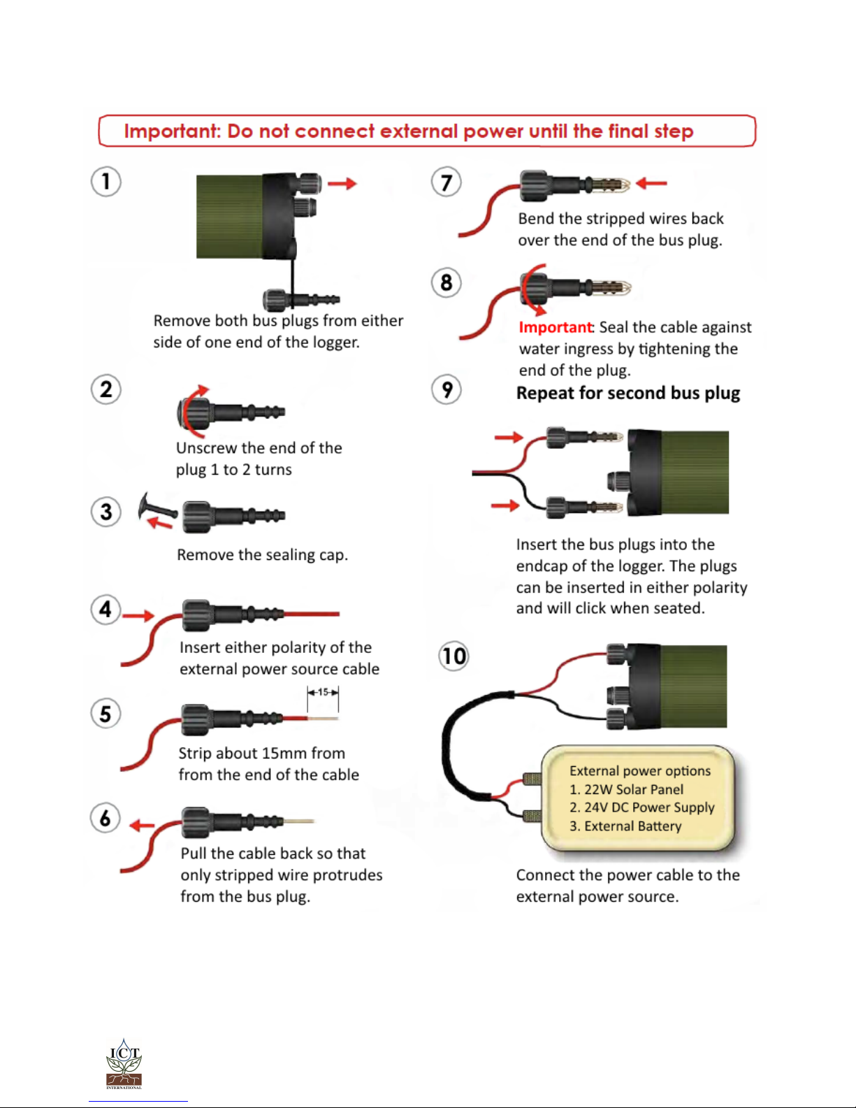
3.1 Connecting a Power Supply to the Instrument.......................................................................................... 7
3.1.1 Individual Power Supply Connections ............................................................................................................. 7
3.1.2 Connecting Power via USB cable to a laptop/PC ........................................................................................ 8
3.1.3 Connecting Power Directly via CH24 Power Supply..................................................................................... 8
3.1.4 Connecting Power Directly via Solar Panel (Field Operation) .................................................................... 8
3.1.5 Connecting Power via External 12V Battery (Field Operation)................................................................... 8
4. Connecting sensors to the SMM.................................................................................................................... 9
4.1 Additional Information on the Breakout Box .............................................................................................. 9
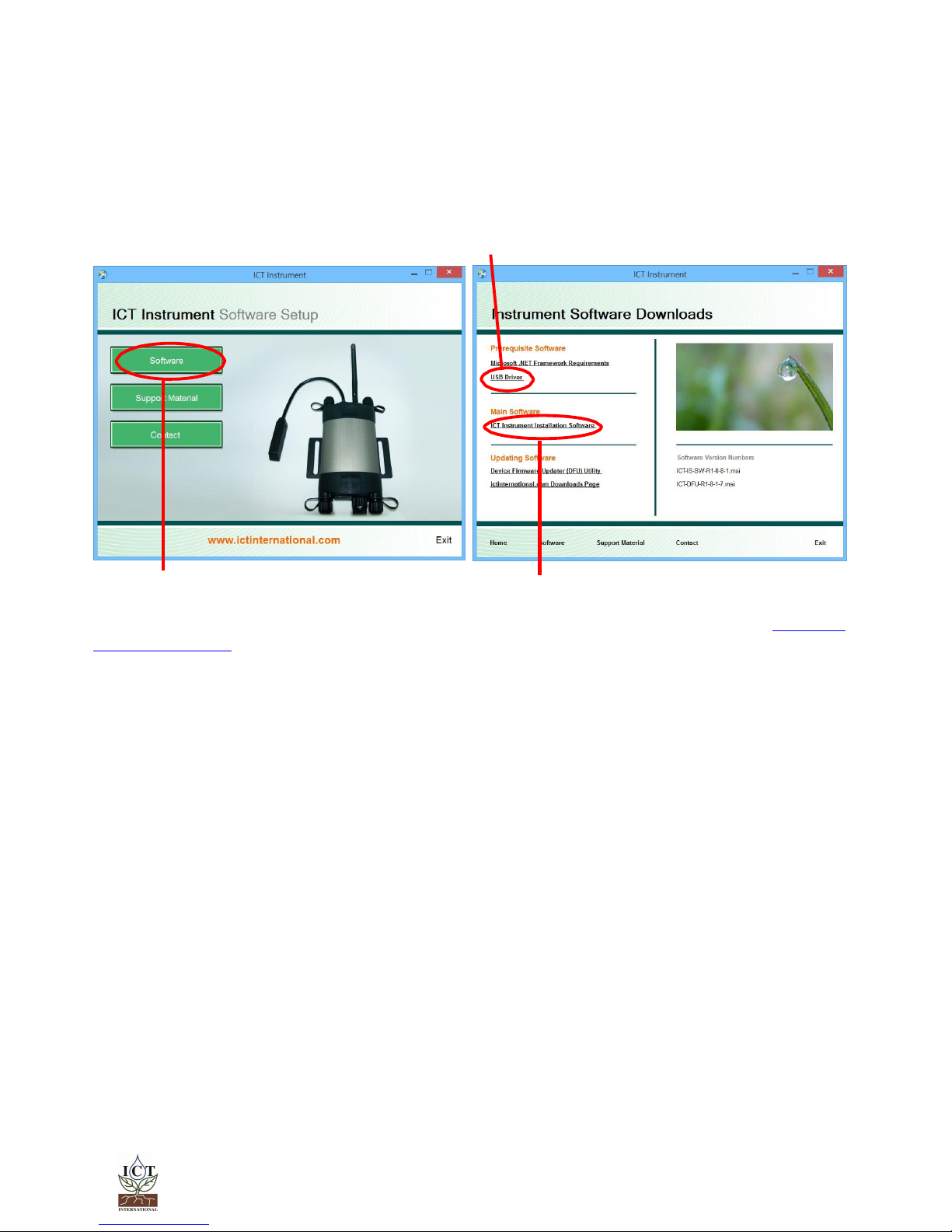
5. Install the SMM Software & USB Driver......................................................................................................... 10
6. Turn the Instrument On................................................................................................................................... 11
7. Connect to the Instrument ........................................................................................................................... 12
7.1 Connect Via USB ............................................................................................................................................ 12
7.2 Connect via MCC Mini................................................................................................................................. 13
8. Set the MeasurementParameters ............................................................................................................... 19
8.1 Configuration.................................................................................................................................................. 20
8.1.1 Settling Time ........................................................................................................................................................ 20
8.1.2 Measurement Sampling Points ........................................................................................................................ 20
8.1.3 Measurement Suspend and Time Delay ....................................................................................................... 21
8.2 Sensor Configuration..................................................................................................................................... 21
8.2.1 Channel Configuration ..................................................................................................................................... 21
8.2.2 Conversion Configuration ................................................................................................................................ 22
8.2.3 Advanced Configuration................................................................................................................................. 22
8.2.4 SD Card Logging Options.................................................................................................................................22
9. Lookup Tables and Scripts ............................................................................................................................ 23
10. Download Data.............................................................................................................................................. 33
11. Appendices..................................................................................................................................................... 35
11.1 User Scripts....................................................................................................................................................... 36
11.1.1 GS1 –Mineral Soil ............................................................................................................................................. 36
11.1.2 GS1 –Soilless Media......................................................................................................................................... 36
11.1.3 10HS –Mineral Soil............................................................................................................................................ 36
11.2 Lookup Tables ................................................................................................................................................ 37
11.2.1 MP306 & MP406 ................................................................................................................................................ 37
11.2.2 SP-110 ................................................................................................................................................................. 37
11.3 MP406 & MP306 Sensor Manual .................................................................................................................. 38
1. Introduction
............................................................................................................................................................. 39
2. Theory of Operation................................................................................................................................................ 40
3. Calibration ................................................................................................................................................................ 42
4. Wiring ......................................................................................................................................................................... 43
Contact Details.............................................................................................................................................................. 45

Enabling better global research outcomes in soil, plant & environmental monitoring. 3
1. Introduction
The SMM Soil Moisture Meter is a complete system for collecting and storing data from up to ten
sensors in the field or in the laboratory. The SMM is equipped with an internal battery which
provides power to the instrument as well as the sensors. A fully charged battery should have the
capacity to provide several hours of data collection in the field before recharging is required.
Depending on logging interval, the internal battery can last several days.
There are three parts to the SMM system:
1. The instrument (or data logger)
2. Breakout box for connection between the sensors and the instrument
3. Sensors
The system is plug-and-play in that it is ready to go from the box. You will need to plug a sensor
into a vacant channel, assign a logging interval, and connect external power supply to the
instrument.
The output from the sensors must be millivolt (mV). The SMM calculates corrected outputs from
either a lookup table or user script supplied with the SMM from ICT International.
This manual outlines how to start your SMM and connect power supply. It also shows how to
download data and configure your instrument.

Enabling better global research outcomes in soil, plant & environmental monitoring. 4
1.1 Instrument Specifications
Instrument Logging
Analogue Channels
Up to 10 single ended/5 differential
Resolution
0.00001V –24-Bit
Accuracy
0.001V
Sampling Frequency
10Hz
Data
Communications
USB, 2.4GHz Wireless RF.
Data Storage
MicroSD card; SD, SDHC and SDXC compatible. FAT32 Format.
Software Compatibility
Windows 7, 8, 8.1 & 10. Mac OS X
Data Compatibility
FAT32 format for direct exchange of MicroSD card with any PC.
Data File Format
Comma Separated Values (CSV) for compatibility with a wide
range of programs.
Memory Capacity
Up to 16GB, 4GB MicroSD card included.
Upgradeable Firmware
User upgradeable firmware using USB boot strap loader function.
Operating Conditions
Temperature Range
-40°C to 80°C
RH Range
0-100%
Power
Internal Battery
960mAh Lithium Polymer, 4.20 volts fully charged
External Power Requirements
Bus Power
8-30 volts DC, non-polarised. Current draw is 190mA maximum at
17 volts.
USB Power
5 volts DC, 100mA fixed charge rate.
Internal Power Management
Fully Charged Battery
4.20 volts
Low Power Mode
3.60 volts –Instrument ceases measurements
Discharged Battery
2.90 volts –Instrument automatically switches off at and below this
voltage when no external power connected.
Battery Life
Varies –with a recommended solar panel or power source
connected, operation can be continuous.

Enabling better global research outcomes in soil, plant & environmental monitoring. 5
2. System Requirements
2.1 Hardware
The ICT Instrument software does not require a powerful computer.
Minimum Recommended System Specifications: Intel Atom 1.66 GHz and 1GB RAM or higher.
2.2 Software
The ICT Instrument software is compatible with the following Operating Systems:
a. Windows 7
b. Windows 8.1
c. Windows 10
d. Mac OS X

Enabling better global research outcomes in soil, plant & environmental monitoring. 6
3. Charging the SMM Internal Battery
The SMM is a self-contained instrument that incorporates a lithium polymer battery. This battery
should be charged before using the instrument. A range of charging options are described on the
next few pages.
The SMM has an internal battery which can supply power for several hours to days depending on
frequency of use. ICT International recommend the internal battery be charged with a solar panel
or other 24V power supply (for example, the ICT CH24 100 - 240Volts AC Mains to 24Volts DC
power supply adapter).
The SMM accepts 8 to 30 volts DC input, maximum charge rate of 200mA is active when the
external voltage rises above 16 Volts DC.
An external power supply can be connected to the SMM in the field. See Connecting a Power
Supply to the Instrument (Field Operation) (pages 10 & 11) for more details.
The unique power-bus plug design was developed by ICT International to simplify the electrical
wiring process. It minimises the need for custom tools in the field requiring only that the outer cable
sheath be stripped back to expose the copper wire.
As shown in Connecting a Power Supply to the Instrument (page 6) no other tools are required
with all necessary components and fixings fully incorporated into the instrument design. Retaining
straps ensure the power-bus plugs do not separate from the instrument when removed from the
power-bus during wiring preparation and connection of external power.

Enabling better global research outcomes in soil, plant & environmental monitoring. 7
3.1 Connecting a Power Supply to the Instrument
3.1.1 Individual Power Supply Connections
Note: The SMM Soil Moisture Meter is non-polarised.

Enabling better global research outcomes in soil, plant & environmental monitoring. 8
3.1.2 Connecting Power via USB cable to a
laptop/PC
3.1.3 Connecting Power Directly via CH24
Power Supply
3.1.4 Connecting Power Directly via Solar
Panel (Field Operation)
3.1.5 Connecting Power via External 12V Battery
(Field Operation)
SMM
SMM
USB Cable
Laptop/PC

Enabling better global research outcomes in soil, plant & environmental monitoring. 9
4. Connecting sensors to the SMM
The sensor is connected to the logger by inserting the green connector into the appropriate
channel in the breakout box supplied with the system.
4.1 Additional Information on the Breakout Box
When your ICT Instrument and breakout box arrives from ICT International you do not have to
change any settings. The ICT Instrument and breakout box has already been configured for your
instrument and sensors.
The breakout box should have the Power Selector Switch ALWAYS set to Internal Battery.
This means that the power supply is coming from the ICT Instrument. If the Power Selector Switch is
set to External Power then voltage is being delivered directly to the breakout box. If the wrong
amount of voltage is supplied to the breakout box then you could potentially damage your
sensors. External power supply is only ever used by advanced users on very rare occasions.
If on the very rare occasion you need to supply external power, ICT recommends you consult with
an ICT engineer or technician first.
If external power is supplied to the breakout box the SW1 Voltage Setting dial becomes important.
The numbers around the dial correspond to column 1 in the SW1 table printed on the breakout
box diagram. The SW1 Voltage Setting Dial controls the supply voltage from the external power. If
the dial is set to 0, the input voltage from the external supply will be 12 Volts. If the dial is set to 1,
then the input voltage from the external supply will be 10 Volts and so on. The level to which you
set the input voltage will depend on your sensor specifications. ICT recommends consulting your
sensor’s manual, manufacturer’s information, or directly contact engineers at ICT.

Enabling better global research outcomes in soil, plant & environmental monitoring. 10
5. Install the SMM Software & USB Driver
Insert the supplied USB drive. You can run CIS.exe and follow the process below, or browse to the
Instrument Software folder and install the ICT Combined Instrument Software and USB driver.
Choose software (a) then choose ICT Instrument Installation Software (b).
The software installation will begin follow the screen prompts until the finished installation screen
appears. To install the USB driver, choose USB Driver (c) and wait for the installation to complete.
(c)
(a) (b)
ICT Combined Instrument Software can also be downloaded from the ICT International Software
Downloads Page.

Enabling better global research outcomes in soil, plant & environmental monitoring. 11
6. Turn the Instrument On
To turn on/charge your SMM Soil Moisture Meter connect the Instrument to a computer via a USB
cable. Alternatively, the SMM can either be turned on manually by pressing the power button or
automatically by connecting an external power supply.

Enabling better global research outcomes in soil, plant & environmental monitoring. 12
7. Connect to the Instrument
7.1 Connect Via USB
Connect the USB cable to the instrument. Open ICT Instrument software and click “Search for
Devices”, then click the named instrument from the Available Devices within the Device Selection
Window.
Click the connect button or double-click the instrument from the list.

Enabling better global research outcomes in soil, plant & environmental monitoring. 13
7.2 Connect via MCC Mini
Ensure that the SMM is on. Connect the MCC Mini to your computer, open ICT Combined
Instrument software. Tick ‘Auto RF Discover’ and then Search for Devices.
The MCC Mini should appear on the list, it will then automatically search for nearby ICT
Instruments.
You can double click the instrument, or select it and Connect, as with USB.
You may need to install the MCC Mini USB driver from the ICT International website:
http://www.ictinternational.com/support/software/

Enabling better global research outcomes in soil, plant & environmental monitoring. 19
8. Set the Measurement Parameters
When you connect to an instrument, the Channels screen will be displayed. This shows the current
measurement status, when the next measurement will take place, the currently configured
channels, instrument serial number/name/comment, battery status, external power status, SD
card status, and the instrument time and date.

Enabling better global research outcomes in soil, plant & environmental monitoring. 20
8.1 Configuration
Normally, all instruments provided by ICT International come pre-configured and tested. All that
you need to do is select a logging interval. This is done from the Configuration screen:
Note: Click ‘Update’ after changing any settings in order to send them to the logger.
A range of standard Measurement Modes are available, from every 1 minute to 60 minutes.
In manual mode a measurement will be taken whenever the Start Measurement button on the
Channels screen is clicked.
If the SMM is in live mode, measurements can be taken from every 250ms to 60 seconds. ICT
recommend connecting the SMM to a continuous external power supply (eg: a CH24) when using
live mode, as this significantly increases the power usage of the logger.
8.1.1 Settling Time
Settling time is the time required for the output of the attached sensors to stabilise after power is
applied. By default, this is set to 5 seconds. Longer settling times will affect the shortest logging
interval. Settling time does not apply to Live Mode.
8.1.2 Measurement Sampling Points
Measurement sampling points are averaged to produce a more stable output. By default, 3
measurements are taken 250ms apart and averaged.
This can be set anywhere from 1 to 10 measurements, 100 to 250ms apart.

Enabling better global research outcomes in soil, plant & environmental monitoring. 21
8.1.3 Measurement Suspend and Time Delay
This option allows you to set a time for the instrument to begin logging. This can be handy for
completely setting up an instrument prior to installation in the field. Logging can be delayed for up
to 24 hours (23:59:59), at which point it will begin to log at the set interval.
8.2 Sensor Configuration
8.2.1 Channel Configuration
Channel configuration allows you to select a conversion table or script to apply to an input
channel. Typically, the appropriate scripts for the sensors will be pre-loaded and configured.
Conversion tables and scripts are covered in Chapter 9.

Enabling better global research outcomes in soil, plant & environmental monitoring. 22
8.2.2 Conversion Configuration
Conversion Configuration allows conversion scripts and tables to be added. These can be
assigned to a channel in Channel Configuration.
When your instrument arrives from ICT International it will be preloaded with all necessary tables
and/or scripts.
8.2.3 Advanced Configuration
The Advanced Configuration section is used to combine 2 single-ended inputs into a single
differential input. This should not be altered unless instructed to do so by ICT International
technical support.
8.2.4 SD Card Logging Options
Options for additional parameters to be logged to the data file. By default, all these options are
enabled. ICT International recommend logging these options.
Raw millivolt data: Raw mV outputs from the sensors. Useful for post processing or changing
conversion options.
Internal battery information: Internal battery voltage and temperature. Used for troubleshooting
and diagnostics.
External supply information: External power supply voltage and current. Used for troubleshooting
and diagnostics.

Enabling better global research outcomes in soil, plant & environmental monitoring. 23
9. Lookup Tables and Scripts
Lookup Tables convert raw millivolt (mV) sensor output into meaningful measurements such as
volumetric soil moisture content (%VWC), temperature, solar radiation, or oxygen concentration.
Lookup Tables need at least 2 values to be valid, and then assume there is a linear relationship
between the 2 values. Typically, the sensors minimum and maximum values are entered. These
values can normally be found on a sensor specification sheet under Range.
Your ICT Instrument has already been pre-programmed with the required Lookup Tables or User
Scripts. You should not need to change any Lookup Tables or User Scripts.
Lookup Tables commonly used for the ICT Instrument described in this manual are found in
Appendix 11.2. If you cannot find the table or script corresponding to your sensor please contact
ICT International.
Lookup tables can be imported/exported as CSV, where column A is mV and column B is the
converted value.
The 2nd and 3rd rows of the table (MP406-VSW%, VSW%) are the name of the conversion table and
the converted unit.
<CSV Table>
MP406-VSW%
VSW%
0
0
120
2
210
5
310
10
415
15
510
20
610
25
720
30
825
35
895
40
955
45
1005
50
1015
55
1025
60
1035
65
1045
70
1055
75
1065
80
1075
85
1085
90
1105
95
1160
100
MP406 lookup table –mV to VSW%.

Enabling better global research outcomes in soil, plant & environmental monitoring. 24
User Scripts allow the conversion of millivolt (mV) sensor output into meaningful measurements,
and are particularly useful if the relationship between mV and the converted value is non-linear.
Scripts can also be used for linear relationships.
User scripts can be imported/exported as .uscr files, which can be opened in notepad or any
similar program. A script can be saved as a .txt and renamed to .uscr.
Line 2 (DBV60) is the name of the script.
Line 3 (mm) is the converted unit.
<User Script>
DBV60
mm
r1 = curchan * 0.0254
res = r1
The instrument scripting language is quite basic, typically only one operation is performed for
each line.
Variables used in scripting are:
r1 to r10
General use registers for storing the value of an
operation.
res
Result register, this value will be displayed as
the converted value.
curchan
mV value of the current channel the script is
executing on. If the script is executing on
channel 1, curchan contains the mV value of
channel 1.
ach1 to ach10
mV value of channels 1 to 10.
ach1c to ach10c
Converted values of channels 1 to 10.
Available operations are:
Operator
Description
=
Assignment. Places the value of the right-hand
variable in the left-hand register.
Example: r1 = ach2
+
Addition.
Example: r1 = curchan + 2
-
Subtraction.
Example: r1 = curchan –3
*
Multiplication.
Example: r1 = curchan * 100
/
Division.
Example: r1 = r1 / 2
inv
Inverse.
Example: r1 = inv r5
sqr
Square.
Example: r1 = sqr ach5

Enabling better global research outcomes in soil, plant & environmental monitoring. 25
sqrt
Square root.
Example: r2 = sqrt r1
log
Natural log.
Example: res = log r5
log10
Base 10 log.
Example: r2 = log10 r1
log2
Base 2 log.
Example: r3 = log2 r1
exp
Exponent e^x
Example: res = exp r2
rnd
Round to the nearest integer.
Example: r5 = rnd r1
(If r1 contains 5.2, r5 will contain 5.0)
abs
Absolute value.
Example: r2 = abs r1
Additional tables and scripts can be found in Appendix 12.1 and 12.2.
Table of contents
Other ICT International Measuring Instrument manuals
Popular Measuring Instrument manuals by other brands

Powerfix Profi
Powerfix Profi 303589 Operation and safety notes

Seametrics
Seametrics AG90 quick start guide

moovo
moovo MU Installation instructions and warnings

GHM
GHM DeltaOHM LPPYRA10 operating manual

Niigata seiki
Niigata seiki SCDI S Series instruction manual

Sun Telecom
Sun Telecom SUN-VFL255N-H Series user manual