ICT International HFM1 User manual

HFM1
Heat Flux Meter
Version VI 2018

Product Warranty
Products manufactured by ICT International are warranted by ICT International to be free
from defects in materials and workmanship under recommended use and service for
twelve (12) months from date of shipment unless otherwise specified. Products not
manufactured, but that are re-sold by ICT International, are warranted only to the limits
extended by the original manufacturer. Batteries, fine-wire thermocouples, desiccant,
and other consumables have no warranty ICT International obligation under this warranty
is limited to repairing or replacing defective products, which shall be the sole and
exclusive remedy under this warranty. The customer shall assume all costs of removing,
reinstalling, and shipping defective products to ICT International. ICT International will
assume all costs of returning products which have been repaired under warranty.
This warranty shall not apply to any products which have been subjected to
modification, misuse, neglect, improper service, accidents of nature, or shipping
damage. This warranty is in lieu of all other warranties, expressed or implied.
Enabling better research outcomes in soil, plant & environmental monitoring.
2

Product Assistance
ICT International products should not be returned without prior authorization. The
following contact information is for ICT international customers residing in countries
served by ICT International. Affiliate companies handle repairs for customers within their
territories. Please visit the ICT International website (http://www.ictinternational.com/
about-us/global-distributors/) to determine which ICT International company serves your
country.
To obtain a Returned Materials Authorization (RMA) form refer to the support page on
the ICT International website (http://www.ictinternational.com/support/), or contact ICT
International on phone number (612) 6772 6770. Advice regarding packaging, shipping
and insurance can be found on the support page of the ICT International website.
It is the customers’ responsibility to comply with all international shipping laws and
regulations, and those domestic shipping laws and regulations that apply to your
country. ICT International will not be held liable for any sanctions or charges laid against
you for not complying with such legislation or regulations.
The ICT International shipping address is:
ICT International Pty Ltd
211 Mann Street, Armidale
NSW, 2350
Australia
Enabling better research outcomes in soil, plant & environmental monitoring.
3

Contents
Product Warranty.............................................................................................................2
Product Assistance..........................................................................................................3
Contents...........................................................................................................................4
1. Introduction.........................................................................................................5
2. HFM1 Software System Requirements...............................................................6
2.1 Hardware.................................................................................................................6
2.2 Software...................................................................................................................6
2.3 ScreenResolution....................................................................................................6
3. Charging the HFM1 Internal Battery..................................................................7
3.1 Connecting a Power Supply to theInstrument..................................................8
3.1.1 Individual Power Supply Connections .................................................................................. 8
3.1.2 Connecting Power Directly via CH24 Power Supply ............................................................. 9
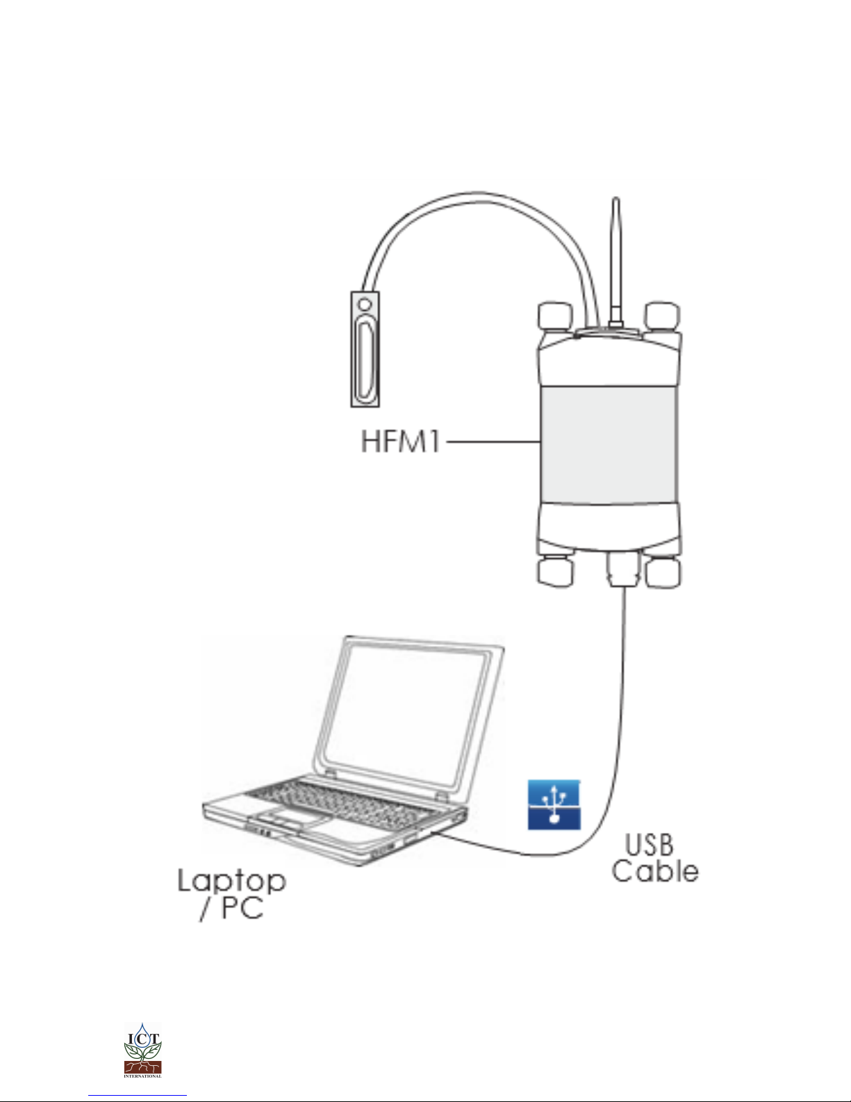
3.1.3 Connecting Power via USB cable to a laptop/PC ................................................................10
3.1.4 Connecting Power via Solar Panel ...................................................................................... 11
4. Connecting sensors to theHFM1.....................................................................12
4.1 Additional Information on the Break-Out Box..................................................13
5. Install the HFM1 Software & USB Driver...........................................................14
6. Turn the HFM1 On..............................................................................................15
7. Connecting to the HFM1..................................................................................16
7.1 Connect via MCC Mini........................................................................................17
8Sensor Configuration........................................................................................18
8.1 Channel Configuration........................................................................................18
8.2 Measurement Suspend and Time Delay...........................................................18
8.3 Conversion Configuration...................................................................................19
8.4 Advanced Configuration....................................................................................19
8.5 SD Card Logging Options...................................................................................19
9. Download Data.................................................................................................20
10. Installation of the HFM1....................................................................................22
10.1 Location of the measurement area..................................................................22
10.2 Mounting of the HFP01 Heat flux sensors...........................................................22
10.2.1 Temporary Installation .......................................................................................................22
10.2.2 Permanent Installation .......................................................................................................22
10.3 Mounting the THERM Temperature sensors.......................................................23
10.3.1 Permanent Installation .......................................................................................................23
11. General theory of the measurement..................................................................................24
1. Introduction and General Theory....................................................................26
11.1 CE declaration of conformity .............................................................................29
Enabling better research outcomes in soil, plant & environmental monitoring.
4

1. Introduction
The HFM1 is a measurement system for analysis of thermal resistance and thermal
transmittance of building elements by in- situ measurement. It can be used for
measurements according to ISO 9869 and ASTM C1155 and C1046 standards. In
its standard configuration the HFM1 system is equipped with:
1. HFM1 Data Logger;
2. HFP01 Heat Flux Plates (2);
3. THERM-MICRO Temperature Sensors (4); and,
4. CH-24 Power Supply.
The HFM1 is a plug-and-play system; the datalogger and sensors are pre-configured by ICT
International. To commence data collection, the user powers the system and assigns a data
logging interval.
The output from the HFP01 sensor sensors is W/m2 and for the temperature sensors is °C.
The HFM1 is powered by an internal battery for short term data collection, and can be
charged using a solar panel or mains power for uninterrupted continuous data collection.
This manual outlines how to deploy a HFM1 for data collection and download, view and
process HFM1 data files.
Enabling better research outcomes in soil, plant & environmental monitoring.
5

2. HFM1 Software System Requirements
2.1 Hardware
Minimum Recommended System Specifications:
Intel Atom 1.66 GHz or AMD equivalent and 1GB RAM or higher.
2.2 Software
The ICT Instrument software is compatible with the following Operating Systems:
a.
Windows 7
b.
Windows 8 & 8.1
c.
Windows 10
d.
Mac OS X
2.3 Screen Resolution
The ICT Instrument software works best on computers that have a screen size of 11.6” or larger
and/or a default screen resolution of 1366 x 768 or larger.
Enabling better research outcomes in soil, plant & environmental monitoring.
6

3. Charging the HFM1 Internal Battery
The HFM1 is a self-contained instrument that incorporates a lithium polymer battery.
Before using the instrument, this battery should be charged. To choose from a range of
charging options see: Connecting a Power Supply to the Instrument on page 10, 11 and 12.
An external power supply should be connected to the HFM1 in the field.
The unique power-bus plug design was developed by ICT International to simplify the
electrical wiring process. It minimizes the need for custom tools in the field requiring only
that the outer cable sheath be stripped back to expose the copper wire.
As shown in Connecting a Power Supply to the Instrument (page 10) no other tools are
required, with all necessary components and fixings fully incorporated into the instrument
design. Retaining straps ensure the power-bus plugs do not separate from the instrument
when removed from the power-bus during wiring preparation and connection of external
power.
Enabling better research outcomes in soil, plant & environmental monitoring.
7

3.1 Connecting a Power Supply to the Instrument
3.1.1 Individual Power Supply Connections
Enabling better research outcomes in soil, plant & environmental monitoring.
8

3.1.2 Connecting Power Directly via CH24 Power Supply
Note: Continuous connection of an external battery or constant power supply
(for days to months at a time) is not recommended as this can shorten the life of
the internal battery. ICT International recommend using a solar panel directly
connected (with no external battery backup in parallel) wherever possible; or a
timer switch to turn off external power for 8-12 hours daily to simulate a solar panel
during the day and night.
Enabling better research outcomes in soil, plant & environmental monitoring.
9

3.1.3 Connecting Power via USB cable to alaptop/PC
Enabling better research outcomes in soil, plant & environmental monitoring.
10

3.1.4 Connecting Power via Solar Panel
Enabling better research outcomes in soil, plant & environmental monitoring.
11

4. Connecting sensors to theHFM1
HFM1 sensors are wired into the logger break-out box channel terminals as detailed
below. HFM1 sensors are wired at ICT.
Logger
Channel Instrument
1 Thermistor excitation reference
2 Spare Single Ended Input
3 HFP01-1 High/+ (Positive Signal)
4 HFP01-1 Low/- (Negative Signal)
5 THERM-1Int
6 THERM-1Ext
7 HFP01-2 High/+ (Positive Signal)
8 HFP01-2 Low/- (Negative Signal)
9 THERM-2Int
10 THERM-2Ext
Enabling better research outcomes in soil, plant & environmental monitoring.
12

4.1 Additional Information on the Break-Out Box
When your HFM1 arrives from ICT International youdo not have to change any of
the break-out box settings, having already been configured for HFP01 and THERM-
MICRO sensors.
The Break-Out box should have the Power Selector Switch always set to Internal
Battery. This means that the power supply is coming from the HFM1. Setting to
External Power and a supplying with an external voltage could potentially damage
you’re the HFM1 sensors.
Enabling better research outcomes in soil, plant & environmental monitoring.
13

5. Install the HFM1 Software & USB Driver
Insert the supplied USB drive and run Autorun.exe.
Choose Software (a) then choose ICT Instrument Software (b).
Follow the on-screen prompts until the finished installation screen appears.
To install the USB driver, choose USB Driver (c) and wait for the installation to complete.
Alternatively, the individual installers (Windows and Mac) are available in the Instrument
Software folder. The most recent versions of all ICT Software are available from:
http://www.ictinternational.com/support/software/
Enabling better research outcomes in soil, plant & environmental monitoring.
14

6. Turn the HFM1 On
To charge and turn on your HFM1, connect the Instrument to a computer via a USB
cable. Alternatively, the HFM1 can either be turned on manually by pressing the
power button or automatically by connecting an external power supply.
Enabling better research outcomes in soil, plant & environmental monitoring.
15

7. Connecting to the HFM1
Connect the USB cable to the instrument and the computer. The HFM1 will automatically be detected by
the computer, as with any USB device. Open ICT Instrument Software and Search for Devices.
Double-click the instrument in the list to connect to it, or select it and click ‘Connect’.
Enabling better research outcomes in soil, plant & environmental monitoring.
16

7.1 Connect via MCC Mini
Ensure that the HFM1 is on. Connect the MCC Mini to your computer, open ICT Combined Instrument
software. Tick ‘Auto RF Discover’ and then Search for Devices.
The MCC Mini should appear on the list, it will then automatically search for nearby ICT Instruments.
You can double click the instrument, or select it and Connect, as with USB.
You may need to install the MCC Mini USB driver from the ICT International website:
http://www.ictinternational.com/support/software/
Enabling better research outcomes in soil, plant & environmental monitoring.
17

8 Sensor Configuration
8.1 Channel Configuration
Channel configuration allows you to select a conversion table or script to apply to an input channel.
Typically, the appropriate scripts for the sensors will be pre-loaded and configured.
8.2 Measurement Suspend and Time Delay
This option allows you to set a time for the instrument to begin logging. This can be handy for completely
setting up an instrument prior to installation in the field. Logging can be delayed for up to 24 hours
(23:59:59), at which point it will begin to log at the set interval.
Enabling better research outcomes in soil, plant & environmental monitoring.
18

8.3 Conversion Configuration
Conversion Configuration allows conversion scripts andtables tobeadded. These can beassigned toa
channel in Channel Configuration.
When your instrument arrives from ICT International it will be preloaded with all necessary tables
and/or scripts.
8.4 Advanced Configuration
The Advanced Configuration section is used to combine 2 single-ended inputs into a single differential
input. This should not be altered unless instructed to do so by ICT International technical support.
8.5 SD Card Logging Options
Options for additional parameters to be logged to the data file. By default, all these options are enabled.
ICT International recommend logging these options.
Raw millivolt data: Raw mV outputs from the sensors. Useful for post processing or changing conversion
options.
Internal battery information: Internal battery voltage and temperature. Used for troubleshooting and
diagnostics.
External supply information: External power supply voltage and current. Used for troubleshooting and
diagnostics.
Enabling better research outcomes in soil, plant & environmental monitoring.
19

9. Download Data
The Data tab can be used for basic data visualisation, SD card management, and to download data files
from the instrument.
Data is stored on the MicroSD card in csv format. The MicroSD card can also be removed from the logger
and read by a computer.
Download saves the instrument data to the Dataview repository and allows for basic graphing from the
data tab. On Windows, the repository is located at: %localappdata%\ICT\Data Files
Select Channels is used to select which logger outputs (channels) are displayed on the plot.
Export provides some options for exporting a CSV file of the data:
Export Clean includes measurement data and column headings.
Export with Headers includes measurement data, column headings and the instrument Serial,
name and comment.
Export a Copy includes all diagnostic data, in addition to the data and headers. This is what is
recorded by the instrument.
Enabling better research outcomes in soil, plant & environmental monitoring.
20
Table of contents
Other ICT International Measuring Instrument manuals
Popular Measuring Instrument manuals by other brands

MONARCH INSTRUMENT
MONARCH INSTRUMENT Pocket Laser Tach 200 instruction manual

Kusam-meco
Kusam-meco KM 033 Operation manual

ARENDO
ARENDO 305660 user manual

Dual
Dual TG12A instructions

Brooks Instrument
Brooks Instrument 1250 Series Installation and operation manual

Horus
Horus HoVR 1.0 BT 2000 owner's manual

Tektronix
Tektronix RSA7100A Quick start user manual

DEVA Broadcast
DEVA Broadcast DVB Explorer Maintenance and operation instruction manual

TSCHORN
TSCHORN 3D Digital operating instructions

Radiodetection
Radiodetection RD4000T3F user manual

ELMACRON
ELMACRON 1000TR instructions

MMF
MMF VM25 instruction manual