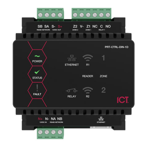
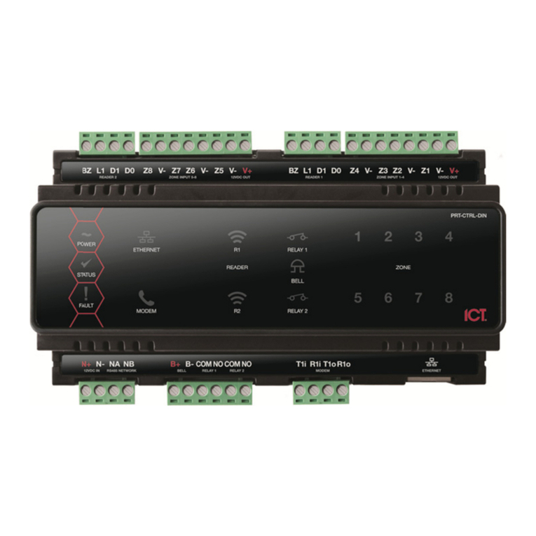
ICT PRT-WX-DIN User manual

PRT-WX-DIN
Using Protege WX
Programming Reference Manual

The specifications and descriptions of products and services contained in this document were correct at the time
of printing. Integrated Control Technology Limited reserves the right to change specifications or withdraw
products without notice. No part of this document may be reproduced, photocopied, or transmitted in any form or
by any means (electronic or mechanical), for any purpose, without the express written permission of Integrated
Control Technology Limited. Designed and manufactured by Integrated Control Technology Limited, Protege® and
the Protege® Logo are registered trademarks of Integrated Control Technology Limited. All other brand or product
names are trademarks or registered trademarks of their respective holders.
Copyright © Integrated Control Technology Limited 2003-2022. All rights reserved.
Last Published: 14-Feb-22 2:51 PM
PRT-WX-DIN | Using Protege WX | Programming Reference Manual 2

Contents
Introduction 8
Controller Models 8
What This Manual Covers 9
Operation Mode 9
System Expansion and Capacities 10
Technical Specifications 11
Getting Started 13
Logging In for the First Time 13
Creating a Secure Password 13
Signing In 14
Registering Your Controller 14
Set the Controller Time 14
Configuring the IP Address 15
Setting Up Integrated DDNS 16
Setting Up an HTTPS Connection 18
Connectivity Requirements for HTTPS 18
Third-Party Certificate 21
Self-Signed Certificate 24
Basic Programming 26
Understanding the Defaults 26
Using the Protege WX Wizards 28
Expanders 28
Access Control 28
Security 28
Users 29
Configuring Additional Areas 30
Creating an Area 30
Pulse Times 30
Configuring Schedules and Holidays 32
Creating Holiday Groups 32
Creating and Editing Schedules 32
Schedules and Multiple Time Spans 33
Rules for Schedules and Holidays 33
Monitoring Your System 34
Viewing Events 34
PRT-WX-DIN | Using Protege WX | Programming Reference Manual 3

Status Lists 34
Reporting 35
Creating an Event Report 35
Exporting Central Station Reports 35
LED Indicators 36
Controller 36
Power Supply (4 Amp) 37
Power Supply (2 Amp) 39
Error Code Display 40
Trouble Inputs 42
Property Reference Guide 43
Users Menu 44
Users 44
Users | Credentials 45
Users | Search 45
Users | Access 45
Users | Options 45
Users | Events 46
Access Levels 47
Access Levels | Doors 47
Access Levels | Door Groups 47
Access Levels | Area Groups 48
Access Levels | Floors 48
Access Levels | Floor Groups 48
Access Levels | Elevator Groups 48
Access Levels | Menu Groups 48
Access Levels | Outputs 48
Access Levels | Output Groups 48
Credential Types 50
User CSV Import 51
Monitoring Menu 52
Reporting | Event Reports 53
Common Reporting Scenarios 53
Event Reports | Users 53
Event Reports | Doors 53
Event Reports | Areas 53
Reporting | Central Station Report 54
PRT-WX-DIN | Using Protege WX | Programming Reference Manual 4

Programming Menu 55
Doors 56
Doors | Outputs 57
Doors | Inputs 58
Doors | Options 59
Doors | Advanced Options 60
Doors | Alarm Options 60
Doors | Events 61
Door Groups 62
Inputs 63
Inputs | Areas and Input Types 63
Inputs | Options 64
Door Types 65
Door Types | Options 66
Input Types 67
Input Types | Options 1 67
Input Types | Options 2 68
Input Types | Options 3 69
Input Types | Options 4 70
Areas 71
Areas | Configuration 71
Areas | Reporting Services 73
Areas | Outputs 73
Areas | Options 1 75
Areas | Options 2 76
Areas | Events 78
Area Groups 79
Outputs 80
Outputs | Options 80
Output Groups 82
Keypad Groups 83
Menu Groups 84
Menu Groups | Keypad Groups 84
Menu Groups | Options 84
Trouble Inputs 86
Trouble Inputs | Areas and Input Types 87
Trouble Inputs | Options 87
PRT-WX-DIN | Using Protege WX | Programming Reference Manual 5

Elevators 88
Elevators | Schedules and Areas 88
Elevator Groups 90
Floors 91
Floor Groups 92
Cameras 93
Phone Numbers 94
Services 95
Contact ID 95
Report IP 97
Automation and Control 99
C-Bus 100
Scheduling Menu 101
Time 102
Holiday Groups 103
Daylight Savings 104
Daylight Savings and Network Time Servers 104
Schedules 105
Schedules | Options 105
Schedules | Holiday Groups 105
Expanders Menu 106
Keypads 107
Keypads | Configuration 107
Keypads | Options 1 107
Keypads | Options 2 108
Analog Expanders 110
Analog Expanders | Channel 1-4 110
Input Expanders 111
Output Expanders 112
Reader Expanders 113
Reader Expanders | Reader 1-2 113
Reader Expanders | Reader 1-2 Options 116
Smart Readers 118
Smart Readers | Reader 118
Expander Addressing 121
Automation Menu 122
Automation | General 122
PRT-WX-DIN | Using Protege WX | Programming Reference Manual 6

Automation | Options 122
Programmable Functions 123
Logic Control 123
Area Control 124
Ripple Output 125
Door Control 125
Virtual Door 127
Input Follows Output 128
Elevator Control 128
System Menu 130
System Settings 131
Settings | Configuration 132
Settings | Options 132
Settings | Email 133
Settings | Custom Reader Format 134
Settings | Security Enhancement 135
Operators 136
Roles 137
Password Policy 138
Maintaining Your System 139
Changing Operator Passwords 139
Backing Up and Restoring Controller Programming 140
Upgrading Application Software and Module Firmware 141
Addressing Expanders 143
Configuring the IP Address 144
Setting the IP Address from a Keypad 145
Temporarily Defaulting the IP Address 146
Defaulting a Controller 148
Troubleshooting 150
Common Health Status Messages 150
Modules that Require a Restart 150
Modules that are Offline 150
Areas Requiring Rearming due to Input Changes 151
Areas with the Tamper Area Disarmed 151
Inputs Assigned an Area but no Input Type 151
Items that Can't Fit in the Database 152
PRT-WX-DIN | Using Protege WX | Programming Reference Manual 7

Introduction
Protege WX is an all-in-one, web-based, cross-platform system that gives you a fully functional access control and
intrusion detection solution in a fraction of the time of conventional software. With no software to install, setup is
quick and simple. Connect the controller and system components, then open a web browser to launch the intuitive
wizard-driven interface which guides you through the process of configuring your system.
For information on installing the controller and other system modules, see the Protege WX DIN Rail Integrated
System Controller Installation Manual.
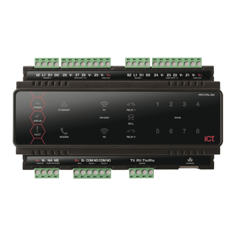
Controller Models
The Controller is the central processing unit responsible for the control of security, access control and automation
in the Protege WX System, and is available in the following models.
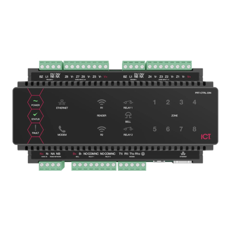
⦁The Protege WX DIN Rail Integrated System Controller (PRT-WX-DIN) has 2 reader ports that can be
independently configured for either Wiegand (up to 1024 bits configurable) or RS-485, allowing connection of
up to 4 readers providing entry/exit control for two doors **.
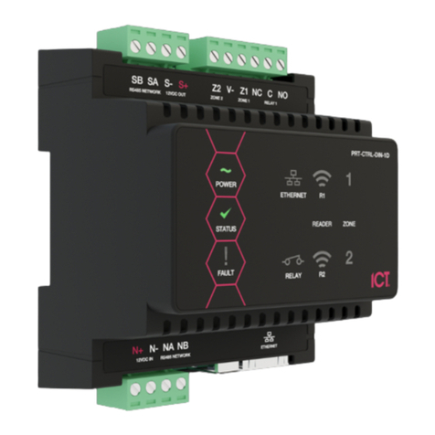
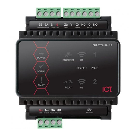
⦁The Protege WX DIN Rail Single Door Controller (PRT-WX-DIN-1D) has 1 RS-485 enabled reader port, allowing
connection of up to 2 RS-485 capable readers providing entry/exit control for a single door.
All models provide onboard access control, with the key difference being the reader ports and number of doors
that can be controlled without the need for additional hardware.
PRT-WX-DIN PRT-WX-DIN-1D
Wiegand Reader Ports 2** -
RS-485 Reader Ports 2** 1
Inputs 8 2
Bell Output 1 -
Outputs (Open Collector) 4 -
Relay Outputs 2 1
Telephone Dialer (for PSTN monitoring) 1 -
** Each reader port supports either Wiegand or RS-485 reader operation, but not both at the same time. If
combining reader technologies, they must be connected on separate ports.
Each port configured for RS-485 operation supports 2 readers, with the wiring identifying which is the entry
reader, and which is the exit reader.
RS-485 reader port connections support configuration for OSDP protocol. The ICT implementation of OSDP
conforms to a subset of the OSDP functionality. For specifications and reader configuration, refer to AN-254
Configuring OSDP Readers, available from the ICT website.
PRT-WX-DIN | Using Protege WX | Programming Reference Manual 8
What This Manual Covers
This manual is divided into the following sections:
⦁Getting Started: Logging in and registering your controller.
⦁Basic Programming: Using the Protege WX configuration wizards to set up your site.
⦁Monitoring Your System: Using the Events page, Status Lists and LED indicators to show what is happening.
⦁Property Reference Guide: An explanation of the available programming options and what they do.
⦁Maintaining Your System: Basic system maintenance, including how to backup and restore controller
programming and update firmware.
⦁Troubleshooting: Helpful troubleshooting information, including how to resolve health status messages.
Operation Mode
Protege WX launches in basic mode with full access control and intrusion detection ready to go. This hides the
more complicated features, making the system more intuitive and simple to use.
Undertake an optional training course to unlock the advanced mode features including building automation,
programmable functions and elevator control.
To find out more about training and unlocking advanced mode, please contact ICT.
PRT-WX-DIN | Using Protege WX | Programming Reference Manual 9

System Expansion and Capacities
The modular-based hardware design provides the flexibility to accommodate any installation, small or large,
residential or commercial. Optional expandable modules allow you to scale your system as your requirements
change. Need more PIRs? Add an input expander. Want more doors? Add a reader expander.
If you reach capacity, you can easily upgrade to the enterprise level Protege GX.
System Capacities Protege WX System
Users 10,000
Events 50,000
Schedules 512
Doors 128
Areas 32
Inputs 512
Outputs 512
Floors 32*
Elevator Cars 8*
Programmable Functions 248*
Keypads 200
Reader Expanders 64
Input Expanders 248
Output Expanders 32
Analog Expanders 32
*Floors, Elevator Cars, and Programmable Functions are only available in Protege WX Advanced mode.
PRT-WX-DIN | Using Protege WX | Programming Reference Manual 10

Technical Specifications
The following specifications are important and vital to the correct operation of this product. Failure to adhere to
the specifications will result in any warranty or guarantee that was provided becoming null and void.
Ordering Information
PRT-WX-DIN Protege WX DIN Rail Integrated System Controller
Power Supply
Operating Voltage 11-14V DC
Operating Current 120mA (Typical)
DC Output (Auxiliary) 10.45-13.85VDC 0.7A (Typical) Electronic shutdown at 1.1A
Bell DC Output (Continuous) 10.4-13.45VDC 8 ohm 30W Siren or 1.1A (Typical) Electronic Shutdown at 1.6A.
Bell DC Output (Inrush) 1500mA
Total Combined Current*3.4A (max)
Electronic Disconnection 9.0VDC
Communication
Communication (Ethernet) 10/100Mbps Ethernet communication link
Communication (RS-485) 3 RS-485 communication interface ports - 1 for module communication, 2 for
reader communication
Communication (Modem) 2400bps modem communication
Readers
Readers
2 reader ports that can be independently configured for either Wiegand (up to
1024 bits configurable) or RS-485, allowing connection of up to 4 readers
providing entry/exit control for two doors **
RS-485 reader port connections support configuration for OSDP protocol
Inputs
Inputs (System Inputs) 8 high security monitored inputs
Outputs
Outputs 4 50mA (max) open collector outputs for reader LED and beeper or general
functions
Relay Outputs 2 Form C relays - 7A N.O/N.C. at 30 VAC/DC resistive/inductive
Dimensions
Dimensions (L x W x H) 156 x 90 x 60mm (6.14 x 3.54 x 2.36")
Net Weight 360g (12.7oz)
Gross Weight 440g (15.5oz)
Operating Conditions
Operating Temperature UL/ULC 0° to 49°C (32° to 120°F) : EU EN -10° to 55°C (14° to 131°F)
Storage Temperature -10˚ to 85˚C (14˚ to 185˚F)
Humidity 0%-93% non-condensing, indoor use only (relative humidity)
PRT-WX-DIN | Using Protege WX | Programming Reference Manual 11

Mean Time Between Failures
(MTBF) 560,421 hours (calculated using RFD 2000 (UTE C 80-810) Standard)
*The total combined current refers to the current that will be drawn from the external power supply to supply the
expander and any devices connected to its outputs. The auxiliary outputs are directly connected via thermal
resettable fuses to the N+ N- input terminals, and the maximum current is governed by the trip level of these fuses.
The Bell output is connected in the same way.
** Each reader port supports either Wiegand or RS-485 reader operation, but not both at the same time. If
combining reader technologies, they must be connected on separate ports.
The ICT implementation of OSDP conforms to a subset of the OSDP functionality. For specifications and reader
configuration, refer to AN-254 Configuring OSDP Readers, available from the ICT website.
The size of conductor used for the supply of power to the unit should be adequate to prevent voltage drop at the
terminals of no more than 5% of the rated supply voltage.
Integrated Control Technology continually strives to increase the performance of its products. As a result these
specifications may change without notice. We recommend consulting our website (www.ict.co) for the latest
documentation and product information.
PRT-WX-DIN | Using Protege WX | Programming Reference Manual 12

Getting Started
This section outlines the process for logging in for the first time and performing initial system configuration.
Logging In for the First Time
The web interface can be accessed by entering the controller's current IP address into the address bar of a
browser, then logging in with valid credentials.
Protege controllers come equipped with a factory loaded HTTPS certificate, ensuring a secure encrypted web
connection. This means HTTPS must be used when accessing the web interface (e.g. https://192.168.1.2). The
factory loaded HTTPS certificate is a self-signed certificate, so when connecting to the controller's web
interface a certificate warning may be displayed, but your connection is still secure.
For older controllers not equipped with a default certificate, HTTPmust be used to connect to the interface.
When using Safari, ensure that private browsing mode is disabled. This applies to all versions of Safari: Mac, iPad
and iPhone. If private browsing mode is enabled an error message prompts you to disable it.
To log in to the controller for the first time, open a web browser and enter the default IP address of 192.168.1.2
with the prefix https:// (e.g. https://192.168.1.2).
If you cannot access the controller with this URL, remove the https:// prefix and try again (e.g. 192.168.1.2).
If you are presented with a security warning when accessing the HTTPS web page, use the advanced options to
proceed to the controller web page.
Once you connect to the controller's web interface you will be prompted to create the admin operator, which is
the default login for accessing the web interface.
Creating the Admin Operator
Thecontroller's factory default settings do not contain a default operator. When a controller is first connected or
has been factory defaulted you will be prompted to Create Admin Operator. The admin operator must be added
before the controller can be accessed and configured through the web interface.
Earlier versions of the controller firmware have a preconfigured admin operator. If you are not prompted to create
a new operator you can log in using the default username admin with the password admin.
1. Add a Username for the admin operator. This does not need to be 'admin'.
2. Choose a Password for the admin operator. The password cannot be blank or 'admin'.
3. Verify Password.
Avery secure password is recommended for the admin operator (see Creating a Secure Password).
Creating a Secure Password
When creating or changing the admin operator password it is highly recommended that you create a very secure
password.
As a guideline, a secure password should include these features:
⦁Minimum 8 characters in length
⦁Combination of upper and lower case letters
⦁Combination of numbers and letters
⦁Inclusion of special characters
PRT-WX-DIN | Using Protege WX | Programming Reference Manual 13

Signing In
To access the system after the initial setup you need to sign in with a valid operator username and password.
1. Open a web browser and enter the controller's IP address, with the prefix https:// (e.g. https://192.168.1.2).
If you cannot access the controller with this URL, remove the https:// prefix (e.g. 192.168.1.2).
2. If you are presented with a security warning when accessing the HTTPS web page, use the advanced options
to proceed to the controller web page.
3. The Sign In window is displayed.
4. Enter your operator Username and Password.
5. Click Sign In.
Repeatedly entering incorrect passwords at the sign in window forces a login stand down. Three consecutive
incorrect attempts will result in the sign in process being locked for 5 seconds. If another three attempts fail, the
sign in process is locked for 60 seconds between all subsequent attempts until a valid login is made. It is not
possible to configure the length of time for the login stand down.
Registering Your Controller
Once logged in, you will be prompted to register your controller:
1. Navigate to System | Licensing and select the License Update tab.
2. Enter your Site and Installer details.
3. Select the Automatic or Manual option to download and activate your Protege WX license.
To Automatically Activate Your License:
4. Click Download License.
5. Your details are passed to the ICT web registration service, then your license is activated automatically.
Important: The automatic activation process requires an internet connection on the workstation you are using to
connect to the controller. If this is not available, you will need to use the manual activation option.
To Manually Activate Your License:
4. Click Generate File to create a license request file. When prompted, save the .req file to a folder on your
network or a portable drive.
5. Click on the link to select your licensing options. This opens a web page where you will be prompted to enter
your site, installer, and serial number details.
6. Browse to the saved .req file and click Submit.
7. Your details are passed to the web registration service. Once registration is complete you will be prompted to
download your license (*.lic) file.
8. Return to Protege WX. Click Browse to select the license file and activate your Protege WX license.
Set the Controller Time
1. Navigate to Scheduling | Time.
2. Click Apply PC Time and Date Now to set the current date and time to that of your PC then click Save.
PRT-WX-DIN | Using Protege WX | Programming Reference Manual 14

Configuring the IP Address
The controller must be programmed with a valid IP address to allow communication. By default this is set to
192.168.1.2 but can be adapted to suit your network requirements and addressing scheme.
If the IP address has been configured previously and you are not sure what it is, you can temporarily default it to
192.168.111.222. For more information, see Temporarily Defaulting the IPAddress.
1. Log in to the controller and navigate to System | Settings.
2. Enter the required settings:
-Use DHCP: When the option is enabled, the controller will use DHCP to dynamically allocate an IP address
instead of using a static IP address.
To use this feature, there must be a DHCP server on the network you are attempting to connect to.
-IP Address: This is the IP address that the controller is currently using. By default this is set to 192.168.1.2.
-Subnet Mask: Used in conjunction with the IP address, a netmask must be configured to allow access to
the appropriate node on the subnet. By default this is set to 255.255.255.0.
-Default Gateway: Used in conjunction with the IP address, the gateway can be configured to allow access
to a router for external communications beyond the subnet to which the controller is connected. By
default this is set to 192.168.1.254.
Set this field to 0.0.0.0 to prevent any external communication.
3. Click Save.
4. Click Restart in the toolbar to restart the controller and implement the changes.
Programming the IP address, subnet mask, and default gateway requires knowledge of the network and subnet
that the system is connected to. You should always consult the network or system administrator before
programming these values.
PRT-WX-DIN | Using Protege WX | Programming Reference Manual 15

Setting Up Integrated DDNS
DDNS (Dynamic Domain Name Server) is a method which allows you to create a static hostname even when the
external IP address of the controller is not fixed. The controller contains an integrated DDNS client which
automatically updates the DDNS provider whenever the IP address changes.
Controllers currently support two DDNS providers: Duck DNS (free provider) and No-IP (free accounts available,
paid plans for further services).
In order to set up DDNS, the controller must be port forwarded so that it is externally accessible.
Setting Up Duck DNS
For two-door controllers, Duck DNS can be used for HTTPS certification via third-party certificates.
1. Browse to Duck DNS and create a free account by signing in with Google or another existing account.
Take note of the Token that is generated when you create your account.
2. Create a new subdomain. The full hostname will have the form [subdomain].duckdns.org.
3. The Current IP field should automatically populate with the external IP address of your network. Ensure that
this is the controller's externally accessible IP address.
4. Access the controller's web interface by typing its IP address into the address bar of a web browser, then log
in with your username and password.
5. Navigate to the System Settings and select the Enable DDNS checkbox.
6. Enter the Hostname [subdomain].duckdns.org and DDNS Server duckdns.org.
7. Leave the DDNS Username blank. For the DDNS Password, enter the Token generated by your Duck DNS
account.
8. Save your settings.
9. Confirm that the controller is externally accessible by browsing to the hostname on another PC.
If the controller's external port is not the default port, you will need to append the port number to the URL
(e.g. controller.duckdns.org:1000).
Setting Up No-IP
The free No-IP Dynamic DNS service does not support third-party certification. This is only supported with the
additional Plus Managed DNS service.
1. Browse to No-IP and create a Dynamic DNS account (free or paid as required).
Free Dynamic DNS hostnames provided by No-IP require confirmation every 30 days, whereas paid accounts
do not.
2. Create a new Hostname and select a Domain.
3. Ensure that the IP Address matches the controller's externally accessible IP address.
4. Access the controller's web interface by typing its IP address into the address bar of a web browser, then log
in with your username and password.
5. Navigate to the System Settings and select the Enable DDNS checkbox.
6. Enter the Hostname and DDNS Server.
7. Enter the Username and Password that you used to sign up to No-IP.
8. Save your settings.
9. Confirm that the controller is externally accessible by browsing to the hostname on another PC.
PRT-WX-DIN | Using Protege WX | Programming Reference Manual 16

If the controller's external port is not the default port, you will need to append the port number to the URL
(e.g. controller.ddns.org:1000).
PRT-WX-DIN | Using Protege WX | Programming Reference Manual 17

Setting Up an HTTPS Connection
One-door controllers currently support self-signed certificates only. Third-party certificates are not supported.
Protege controllers have HTTPS connection enabled by default with a pre-loaded certificate. However, an
alternative certificate can be installed if preferred. Installing a third-party certificate on the controller will remove
the security warning which you may see in your browser when accessing a controller with a factory certificate.
For older controllers not equipped with a default certificate, ICT strongly recommends that all live Protege sites
establish an HTTPS connection between the controller web interface and the web browser. This is especially
important if the controller can be accessed on-site via a router, or externally via the internet.
If the controller is factory defaulted, any user-created HTTPS certificates are removed and the default certificate is
reloaded. Custom certificates will need to be reinstalled.
Two different connection methods are available, each of which can be configured directly within the web
interface:
⦁Validating and installing a third-party certificate obtained from a certificate authority.
⦁Installing a self-signed certificate (recommended for testing only).
For configuration and version requirements refer to AN-280 HTTPS Connection to the Protege WX Controller,
available from the ICT website.
Connectivity Requirements for HTTPS
To acquire a third-party certificate for HTTPS connection to the controller's web interface, the controller must be
accessible over the internet. This section discusses some of these requirements so that the system can be properly
prepared for HTTPS implementation.
Operating on an active network requires knowledge of the configuration and structure of the network. Always
consult the network or system administrator before you begin.
More Information
⦁For detailed networking information, see the Protege WX Network Administrator Guide.
⦁For basic information on Protege WX controller networking see AN-189: Protege WX Connectivity Guide.
Port Forwarding Requirements
In order for the controller to be accessible externally, port forwarding must be configured at the router. Port
forwarding is a method of mapping an IP address and port on a local subnet to an external port, so that the
networked device is accessible over the internet.
In particular, validating a third-party certificate generally requires the controller to be accessible via external port
80. This is the default port for HTTP requests. This external port must be set up to forward traffic to an internal
port on the controller that accepts HTTP requests. By default this is internal port 80; however, if required this can
be changed in the System Settings.
Controller
(IP 192.168.1.2)
Router
(External IP
203.97.123.169)
Internet
Port 80
HTTP Request
Port 80
Once this port has been forwarded, the controller will be accessible via the external IP address of the network. In
this example, typing 203.97.123.169 into an external web browser will open the controller's web interface.
PRT-WX-DIN | Using Protege WX | Programming Reference Manual 18

External access via HTTP is only required in order to validate and install your certificate. Once the certificate has
been installed, HTTP access will be disabled because the more secure HTTPS connection is available. Therefore it
will no longer be necessary to forward external port 80 to the controller.
Port forwarding is configured from the router's utility interface, which can be accessed by browsing to the router's
IP address. Different routers have different interfaces, so it is recommended that you consult the documentation
for your router.
Optional Port Forwarding
After you have installed a certificate and established an HTTPS connection to the controller, you may wish to
continue accessing the controller over the internet. To achieve this, the controller must be accessible via its HTTPS
port. The default HTTPS port is internal port 443, but this can be changed if necessary in the System Settings
(available once Use HTTPS is enabled).
The easiest method is to configure the router to forward all traffic from external port 443 (the default HTTPS
port) to the controller's internal HTTPS port, as in the image below.
Controller
(IP 192.168.1.2)
Router
(External IP
203.97.123.169)
Internet
Port 443
HTTPS Request
Port 443
In this case, all traffic directed to the external HTTPS IP address will be forwarded to the controller. The controller's
web interface could be accessed by typing https://203.97.123.169 into an external web browser.
However, it is possible to grant external access by forwarding any external port to the controller's HTTPS port. This
is especially useful if external port 443 is not available on your network.
Controller
(IP 192.168.1.2)
Router
(External IP
203.97.123.169)
Internet
Port 443
HTTPS Request
Port 1000
In this case, any traffic directed to external port 1000 will be forwarded to the controller's HTTPS port. The
controller's web interface can be accessed simply by appending the external port number onto the end of the URL:
e.g. https://203.97.123.169:1000.
Note: If the controller does not have a factory loaded certificate, it will not be accessible via HTTPS until an HTTPS
certificate has been installed, regardless of whether port forwarding has been configured.
Controller Default Gateway
In order for the controller to send and receive external communications via the router, its default gateway needs to
be set to the router's internal IP address.
1. Log in to the controller's web interface and navigate to System Settings.
2. In the Default Gateway field, enter the IPaddress of the router.
3. Save the configuration and Restart the controller.
Note:The default gateway must be set to the router's internal IPaddress that identifies it on the local internal
network, not the external IPaddress used to connect over the internet.
PRT-WX-DIN | Using Protege WX | Programming Reference Manual 19

Mapping an IP Address to a Domain
In order to achieve third-party HTTPS certification, it is necessary to map the controller's externally accessible IP
address to a domain. The domain name becomes the hostname for the controller: a fixed, human readable point of
access to the device.
Domain names can be purchased from Domain Name Registrars and assigned to a static IP address, usually for an
annual fee. For example, the IP address 203.97.123.169 could be assigned the domain name controller.com, and
would then be accessible by typing that domain name into a browser address bar.
However, typically routers are assigned a dynamic IP address. This IP address is not static: internet service
providers may reassign the address whenever the router is reset or even more frequently. A fixed domain name
would have to be constantly monitored and updated, as the IP address it is mapped to will change unpredictably.
If necessary, a static IP address may be purchased from your internet service provider.
Alternatively, you may use a Dynamic Domain Name Server (DDNS), which allows a dynamic IP address to be
mapped to a static domain name. Generally a DDNS service will provide a client application which runs on the web
server PC and automatically updates the domain's IP address mapping whenever the external IP address changes.
Controllers also have an integrated DDNS client which supports several free DDNS providers.
PRT-WX-DIN | Using Protege WX | Programming Reference Manual 20
Other manuals for PRT-WX-DIN
1
This manual suits for next models
1
Table of contents
Other ICT Controllers manuals

ICT
ICT Protege WX User manual

ICT
ICT PRT-CTRL-DIN-1D User manual

ICT
ICT Protege SE User manual

ICT
ICT PRT-WX-DIN-1D User manual

ICT
ICT PRT-WX-DIN-1D User manual

ICT
ICT PRT-CTRL-DIN User manual

ICT
ICT Protege GX DIN Rail System Controller User manual

ICT
ICT Protege GX User manual

ICT
ICT PRT-WX-DIN User manual

ICT
ICT PRT-CTRL-DIN-1D User manual