manuals.online logo
Brands
  1. Home
  2. •
  3. Brands
  4. •
  5. ICT
  6. •
  7. Power Supply
  8. •
  9. ICT COMM SERIES User manual

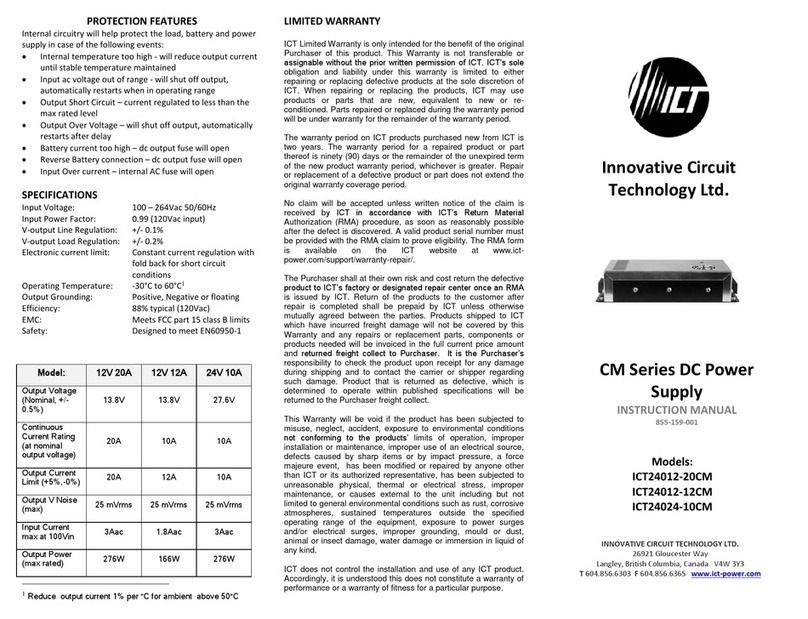
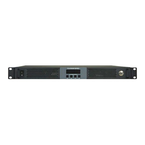
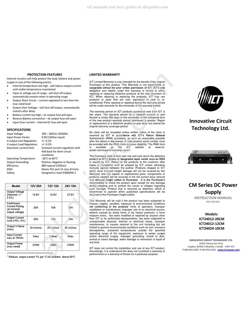
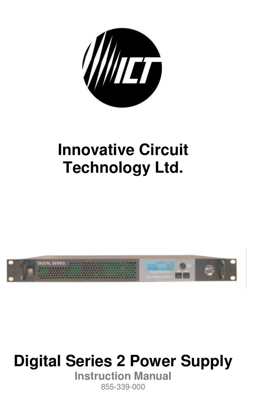
ICT COMM SERIES User manual

THEPOWEROFRELIABILITY
INNOVATIVE CIRCUIT TECHNOLOGY LTD.
855-040-004
ICT COMM SERIES
INSTRUCTION MANUAL
SPECIFICATIONS
Input
Voltage
Range
Available Configurations Output
Voltage
Output
Current
(Cont.)
Output
Current
(Peak)
Current
Limiting
Line
Regulation
Load
Regulation
Output
Ripple
(Max)
Efficiency
(Typical)
AGA AX ARMARAM
ICT12012-8 (1)(2)
ICT12012-10 (1)(2)
ICT12012-11 (1)(2)
ICT12012-12 (1)(2)
ICT12024-5 (1)
ICT12048-3
ICT22012-8 (3)
ICT22012-10 (3)
ICT22012-11 (3)
ICT22012-12 (3)
ICT22024-5
ICT22048-3
90-130 VAC 13.8 VDC
+/- 150 mV
6.5 Amps 8.0 Amps 8.5 Amps 0.20% 0.50% 20 mV RMS 85%
90-130 VAC 13.8 VDC
+/- 150 mV
7.5 Amps 10.0 Amps 10.5 Amps 0.20% 0.75% 20 mV RMS 85%
90-130 VAC 13.8 VDC
+/- 150 mV
9.0 Amps 11.0 Amps 11.5 Amps 0.20% 0.50% 20 mV RMS 85%
90-130 VAC 13.8 VDC
+/- 150 mV
10.0 Amps 12.0 Amps 12.5 Amps 0.20% 0.80% 20 mV RMS 85%
90-130 VAC 27.6 VDC
+/- 150 mV
4.0 Amps 5.0 Amps 5.5 Amps 0.20% 0.75% 20 mV RMS 85%
90-130 VAC 48.0 VDC
+/- 150 mV
2.5 Amps 3.0 Amps 3.5 Amps 0.50% 1.00% 20 mV RMS 85%
105-130/
180-265 VAC
13.8 VDC
+/- 150 mV
6.5 Amps 8.0 Amps 8.5 Amps 0.20% 0.50% 35 mV RMS 80%
105-130/
180-265 VAC
13.8 VDC
+/- 150 mV
7.5 Amps 10.0 Amps 10.5 Amps 0.20% 0.75% 20 mV RMS 85%
105-130/
180-265 VAC
13.8 VDC
+/- 150 mV
9.0 Amps 11.0 Amps 11.5 Amps 0.20% 0.50% 20 mV RMS 85%
105-130/
180-265 VAC
13.8 VDC
+/- 150 mV
10.0 Amps 12.0 Amps 12.5 Amps 0.20% 0.80% 20 mV RMS 85%
180-265 VAC 27.6 VDC
+/- 150 mV
4.0 Amps 5.0 Amps 5.5 Amps 0.20% 0.50% 20 mV RMS 85%
180-265 VAC 48.0 VDC
+/- 150 mV
2.5 Amps 3.0 Amps 3.5 Amps 0.50% 1.00% 35 mV RMS 80%
ICT12012-4 90-130 VAC 13.8 VDC
+/- 300mV
3.0 Amps 4.0 Amps 4.5 Amps 0.50% 2.00% 20 mV RMS 75%
ICT12012-6 90-130 VAC 13.8 VDC
+/- 300mV
4.5 Amps 6.0 Amps 6.5 Amps 0.50% 2.00% 20 mV RMS 75%
ICT22012-4 105-250 VAC 13.8 VDC
+/- 300mV
3.0 Amps 4.0 Amps 4.5 Amps 0.50% 2.00% 25 mV RMS 75%
105-250 VAC 13.8 VDC
+/- 300mV
4.5 Amps 6.0 Amps 6.5 Amps 0.50% 2.00% 25 mV RMS 75%
105-250 VAC 27.6 VDC
+/- 400mV
2.5 Amps 3.0 Amps 4.0 Amps 1.00% 2.00% 35 mV RMS 75%
ICT22012-6
ICT22024-3
ICT12012-15 (1)(2)
ICT12012-20 (1)(2)
ICT12012-30 (1)(2)
ICT12024-10 (1)(2)
ICT12024-15 (1)(2)
ICT12048-5
ICT22012-15 (1)(3)
ICT22012-20 (1)(3)
ICT22012-30 (1)(3)
ICT22024-10 (3)
ICT22024-15 (3)
ICT22048-5 (3)
90-130 VAC 13.8 VDC
+/- 150 mV
13.0 Amps 15.0 Amps 15.5 Amps 0.20% 0.80% 20 mV RMS 85%
90-130 VAC 13.8 VDC
+/- 150 mV
17.0 Amps 20.0 Amps 20.5 Amps 0.20% 0.85% 20 mV RMS 85%
90-130 VAC 13.8 VDC
+/- 150 mV
25.0 Amps 30.0 Amps 31.0 Amps 0.20% 0.85% 20 mV RMS 85%
90-130 VAC 27.6 VDC
+/- 150 mV
8.0 Amps 10.0 Amps 10.5 Amps 0.20% 0.75% 20 mV RMS 85%
90-130 VAC 27.6 VDC
+/- 150 mV
13.0 Amps 15.0 Amps 15.5 Amps 0.20% 0.75% 20 mV RMS 85%
90-130 VAC 48.0 VDC
+/- 150 mV
4.0 Amps 5.0 Amps 5.5 Amps 0.50% 1.00% 40 mV RMS 80%
90-130/
180-265 VAC
13.8 VDC
+/- 150 mV
13.0 Amps 15.0 Amps 15.5 Amps 0.20% 0.80% 20 mV RMS 85%
90-130/
180-265 VAC
13.8 VDC
+/- 150 mV
17.0 Amps 20.0 Amps 20.5 Amps 0.20% 0.85% 20 mV RMS 85%
90-130/
180-265 VAC
13.8 VDC
+/- 150 mV
25.0 Amps 30.0 Amps 31.0 Amps 0.20% 0.85% 25 mV RMS 85%
90-130/
180-265 VAC
27.6 VDC
+/- 150 mV
8.0 Amps 10.0 Amps 10.5 Amps 0.20% 0.75% 20 mV RMS 85%
90-130/
180-265 VAC
27.6 VDC
+/- 150 mV
13.0 Amps 15.0 Amps 15.5 Amps 0.20% 0.75% 20 mV RMS 85%
90-130/
180-265 VAC
48.0 VDC
+/- 150 mV
4.0 Amps 5.0 Amps 5.5 Amps 0.50% 1.00% 40 mV RMS 80%
A - Standard 7.1" Width
AG - 6.4" Width
AX - 5.6" Width
AM - with LCD Meter
AR - mounted on 19" Rackmount
ARM - with LCD Meter and Rackmount
(1) CSA C22.2 No 107.1, UL 1012 Approved
(2) FCC class B Compliant
(3) Switchable between 120 & 220 VAC Input - Internal Jumper
10 - 100 watts100 - 200 watts200 - 500 watts
ICT Ltd. warrants to the original consumer purchaser that this
product shall be in good working order, free from defects in
materials and workmanship, for a period of one (1) year from the
date of purchase. Should failure occur during the above stated time
period, then ICT will, at its option, repair or replace this product at
no additional charge except as set forth below. All parts, whether
for repair or replacement, will be furnished on an exchange basis.
All exchange pieces become the property of ICT. This limited
warranty shall not apply if the ICT product has been damaged by
unreasonable use, accident, negligence, disaster, service, or
modification by anyone other than the ICT factory.
Limited warranty service is obtained by delivering the product
during the above stated one (1) year warranty period to an
authorized ICT dealer or ICT factory and providing proof of purchase
date. If this product is delivered by mail, you will insure the product
or assume risk of loss or damage in transit, and prepay shipping
charges to the factory.
Every reasonable effort has been made to ensure that ICT product
manuals and promotional materials accurately describe ICT product
specifications and capabilities at the time of publication. However,
because of ongoing improvements and updating of ICT products,
ICT cannot guarantee the accuracy of printed materials after the
date of publication and disclaims liability for changes, errors or
omissions.
If this ICT product is not in good working order, as outlined in the
above warranty, your sole remedy shall be repair or replacement as
provided above. In no event will ICT be liable for any damages
resulting from the use of or the inability to use the ICT product,
even if an ICT employee or an authorized ICT dealer has been
advised of the possibility of such damages, or for any claim by any
other party.
ICT reserves the right to make changes without further notice to
any products or documentation for improvement of reliability,
function, or design.
ICT Ltd. does not recommend use of its products in life support
applications wherein a failure or malfunction of the product may
directly or indirectly threaten life or cause injury. The user of ICT
products, which are to be used in life support applications as
described above, assumes all risks of such use and indemnifies ICT
against all damages.
This device complies with Part 15 of the FCC Rules. Operation is
subject to the following 2 conditions:
1. This device may not cause harmful interference, and
2. This device must accept any interference received, including
any interference that may cause undesired operation.
LIMITED WARRANTY
INNOVATIVE CIRCUIT TECHNOLOGY LTD.
26921 GLOUCESTER WAY LANGLEY, BRITISH COLUMBIA, CANADA V4W 3Y3
T 604.856.6303 F 604.856.6365 www.ict-power.com
NOTES
The ICT Comm Series can be used in parallel or series
configurations. Please contact ICT for further information.
Most ICT Comm series products are available in various
widths (A = 7.11", AG = 6.4", AX = 5.6") and can be
assembled with a wide variety of ICT base station covers.
120/220 Volt or 220 Volt input models are available, as well as
12, 24, and 48 V output models. Options available also include
an LCD meter for current and voltage display, and a 19"
rackmount configuration. Wallmount brackets are available for
permanent installation. (part #ICT-WMB)
The ICT Comm Series can also be used to charge a battery
while powering an accessory without any modification. Please
contact ICT for design note (DN-101 Battery backup).
The ICT Charger Series is also available, which offer a
complete microprocessor controlled battery backup system.
They feature fast and efficient 3 stage battery charging, as
well as full protection for both the battery and the charger.




Do not block side or bottom vent slots.
Do not place unit on or near sources of heat/moisture.
Incorrect wiring may result in serious damage to both power
supply and equipment wired to power supply.
Unit service should be done by ICT.
SETUP
ICT COMM SERIES
WARNING
The ICT Comm Series switching power supplies deliver continuous
trouble-free operation and incorporate extra filtering, providing a
virtually noise-free environment for a wide range of
communications equipment and 12V accessories.
These instructions should be read before using the product and it
should be saved for future reference.
Plug the enclosed power cord into the input plug on the back
of the unit. Plug the other end into the AC outlet.
Connect equipment to terminal block at the rear of the unit.
Note: Keep the hook-up leads to the load as short as possible
to avoid excess radiated noise.
To turn on power supply, press top of front panel switch.







AX
AG
A
AX
AG
A
CONNECTIONS
10 - 100 watts
100 - 200 watts
200 - 500 watts
SIGNED OFF BY:
Other ICT Power Supply manuals

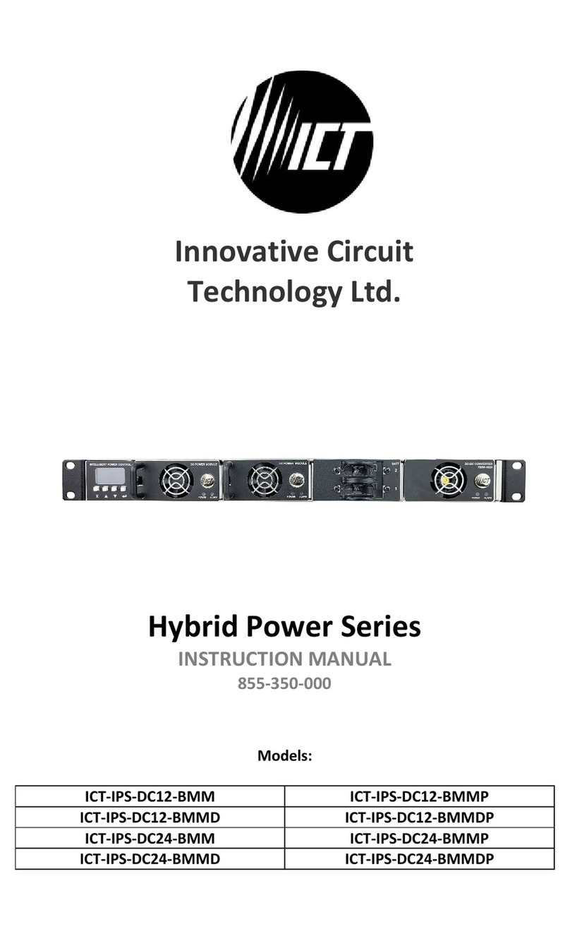
ICT Hybrid Power ICT-IPS-DC12-BMM User manual

ICT

ICT Hybrid Power ICT-IPS-DC12-BMM User manual

ICT ICT24012-20CM User manual

ICT

ICT ICT24012-20CM User manual

ICT Bill Validator S6 Series User manual

ICT

ICT Bill Validator S6 Series User manual

ICT ICT12012-10A User manual

ICT

ICT ICT12012-10A User manual

ICT Platinum Series User manual

ICT

ICT Platinum Series User manual

ICT ICT24012-10CM User manual

ICT

ICT ICT24012-10CM User manual

ICT ISOLATED 2 Series User manual

ICT

ICT ISOLATED 2 Series User manual

ICT ICT-2U4 User manual

ICT

ICT ICT-2U4 User manual

ICT Protege PRT-PSU-DIN-8A User manual

ICT

ICT Protege PRT-PSU-DIN-8A User manual

ICT PRT-PSU-DIN-4A User manual

ICT

ICT PRT-PSU-DIN-4A User manual

ICT PRT-PSU-DIN-2A User manual

ICT

ICT PRT-PSU-DIN-2A User manual

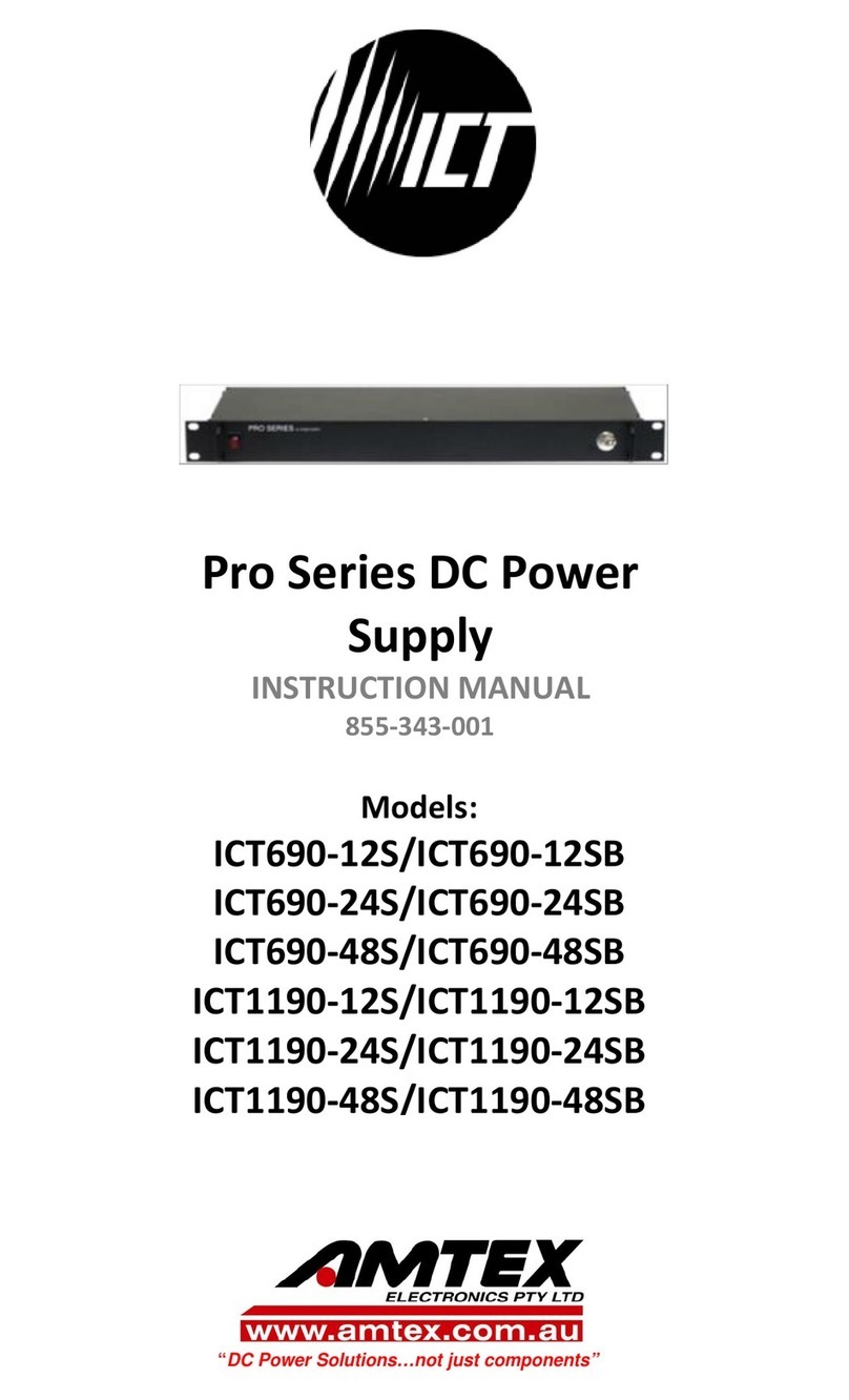
ICT Pro Series User manual

ICT

ICT Pro Series User manual

ICT ICT690-12S User manual

ICT

ICT ICT690-12S User manual

Popular Power Supply manuals by other brands

Bluetti EP500 user manual

Bluetti

Bluetti EP500 user manual

Antec VP350P user manual

Antec

Antec VP350P user manual

TEM EM66 quick start guide

TEM

TEM EM66 quick start guide

Teledyne T3PS40381P quick start guide

Teledyne

Teledyne T3PS40381P quick start guide

TekPower TP-3005D manual

TekPower

TekPower TP-3005D manual

TDK-Lambda GENESYS GH1.5kW in 1U Half-Rack 0-600V /... manual

TDK-Lambda

TDK-Lambda GENESYS GH1.5kW in 1U Half-Rack 0-600V /... manual

Enterasys Matrix X Router installation guide

Enterasys

Enterasys Matrix X Router installation guide

C-COR Optiworx HW Series Procedures manual

C-COR

C-COR Optiworx HW Series Procedures manual

Aaeon PFM-P13D Quick installation guide

Aaeon

Aaeon PFM-P13D Quick installation guide

NAPCO NP-P5A instructions

NAPCO

NAPCO NP-P5A instructions

Weinzierl KNX PowerSupply 365 Installation and operation manual

Weinzierl

Weinzierl KNX PowerSupply 365 Installation and operation manual

Texas Instruments ADS868 A Series manual

Texas Instruments

Texas Instruments ADS868 A Series manual

Truma iNet Box operating instructions

Truma

Truma iNet Box operating instructions

Motorola FPN5590B Operator's manual

Motorola

Motorola FPN5590B Operator's manual

Hamamatsu Photonics C9525 SERIES instruction manual

Hamamatsu Photonics

Hamamatsu Photonics C9525 SERIES instruction manual

Thermolec DCC-9 Series installation manual

Thermolec

Thermolec DCC-9 Series installation manual

Huawei UPS5000-H-400 kVA user manual

Huawei

Huawei UPS5000-H-400 kVA user manual

Lenze E94APNE0 4 Series Mounting instructions

Lenze

Lenze E94APNE0 4 Series Mounting instructions

manuals.online logo
manuals.online logoBrands
  • About & Mission
  • Contact us
  • Privacy Policy
  • Terms and Conditions

Copyright 2025 Manuals.Online. All Rights Reserved.