Icy Box IB-EW205B-T User manual
IB-EW205B-T
Manual IB-EW205B-T
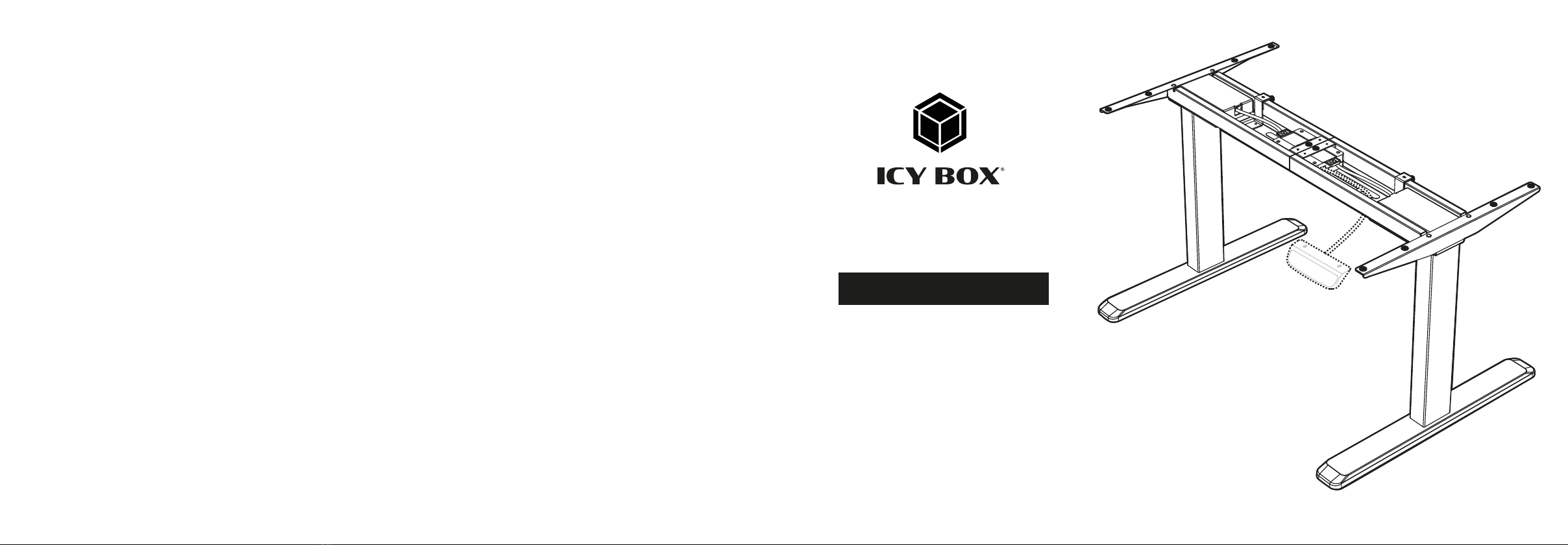
Electrically height-adjustable sit-stand desk frame
Handbuch IB-EW205B-T
Elektrisch höhenverstellbares Sitz-Steh-Tischgestell
Preface
This electric height-adjustable table frame consists of a heavy-duty metal frame and a motorised height adjustment system. Please read these instructions
completely before installation to ensure safe and correct use and to avoid damage to the electronics or the table frame.
• Do not cover the fan outlet and passive cooling elements
• Avoid direct sunlight on the device/power unit
• Guarantee sufficient ambient air for the device/power unit
• Do not place objects on the device/power unit
4. Hazards caused by very small parts and packaging
Risk of suffocation
Risk of death by suffocation or swallowing
• Keep small parts and accessories away from children
• Store/dispose of plastic bags and packaging in an area that is inaccessible to children
• Do not hand over small parts and packaging to children
5. Potential data loss
Data loss during commissioning
Potentially irreversible data loss
• Always comply with the information in the operating instructions/quick installation guide
• Use the product only wonce the specifications have been met
• Back up data prior to commissioning
• Back up data prior to connecting new hardware
• Use accessories enclosed with the product
6. Cleaning the device
Harmful cleaning agents
Scratches, discolouration, damage caused by moisture or short
circuit in the device
• Disconnect the device prior to cleaning
• Aggressive or intense cleaning agents and solvents are unsuitable
• Make sure there is no residual moisture after cleaning
• We recommend cleaning devices using a dry, anti-static cloth
7. Disposing of the device
Environmental pollution, unsuitable for recycling
Potential environmental pollution caused by components, recycling
circle interrupted
This icon on product and packaging indicates that this product must not be disposed
of as part of domestic waste. In compliance with the Waste Electrical and Electronic
Equipment Directive (WEEE) this electrical device and potentially included batteries
must not be disposed of in conventional, domestic waste or recycling waste. If
you would like to dispose of this product and potentially included batteries, please
return it to the retailer or your local waste disposal and recycling point.
The included batteries must be completely discharged before return.
Take precaution to protect the batteries from short circuits (e.g. by insulating the contact poles
with adhesive tape)
If you have any questions, please do not hesitate to contact our support at
WARNING
IMPORTANT
IMPORTANT
IMPORTANT
Please read carefully the following information to prevent injuries, damage to ma-
terial and device as well as data loss:
Warning levels
Signal words and safety codes indicate the warning level and provide immediate information in
terms of the probability of occurrence as well as the type and severity of the consequences if the
measures to prevent hazards are not complied with.
Warns of a directly hazardous situation causing death or
serious injury.
Warns of a potentially hazardous situation that may cause death
or serious injury.
Warns of a potentially hazardous situation that may cause minor
injury.
Warns of a potential situation that may cause material or environ-
mental damage and disrupt operative processes.
1. Risk of electrical shock
Contact with parts conducting electricity
Risk of death by electrical shock
• Read the operating instructions prior to use
• Make sure the device has been de-energised prior to working on it
• Do not remove contact protection panels
• Avoid contact with conducting parts
• Do not bring plug contacts in contact with pointed and metal objects
• Use in intended environments only
• Operate the device using a power unit meeting the specifications of the type plate only!
• Keep the device/power unit away from humidity, liquid, vapour and dust
• Do not modify the device
• Do not connect the device during thunderstorms
• Approach specialist retailers if you require repairs
2. Hazards during assembly (if intended)
Sharp components
Potential injuries to fingers or hands during assembly (if intended)
• Read the operating instructions prior to assembly
• Avoid coming into contact with sharp edges or pointed components
• Do not force components together
• Use suitable tools
• Use potentially enclosed accessories and tools only
3. Hazards caused by a development of heat
Insufficient device/power unit ventilation
Overheating and failure of the device/power unit
• Prevent externally heating up components and ensure an exchange of air
DANGER
WARNING
CAUTION
IMPORTANT
WARNING
CAUTION
IMPORTANT
• externe Erwärmung vermeiden und Luftaustausch zulassen
• Lüfterauslass und passive Kühlkörper freihalten
• direkte Sonneneinstrahlung auf Gerät/Netzteil vermeiden
• ausreichend Umgebungsluft für Gerät/Netzteil sicherstellen
• keine Gegenstände auf dem Gerät/Netzteil abstellen
4. Gefahren durch Kleinstteile und Verpackung
Erstickungsgefahr
Lebensgefahr durch Ersticken oder Verschlucken
• Kleinteile, Zubehör für Kinder unzugänglich verwahren
• Plastiktüten und Verpackung für Kinder unzugänglich verwahren/entsorgen
• Kleinteile und Verpackungen nicht in Kinderhände geben
5. Möglicher Datenverlust
Datenverlust bei Inbetriebnahme
Unwiederbringlicher Datenverlust möglich
• Unbedingt Hinweise in der Bedienungsanleitung/Schnellinstallationsanleitung beachten
• Produkt nur verwenden, wenn Spezifikationen erfüllt sind
• Datensicherung vor Inbetriebnahme durchführen
• Datensicherung vor Anschluss neuer Hardware durchführen
• dem Produkt beiliegendes Zubehör verwenden
6. Reinigung des Gerätes
Schädigende Reinigungsmittel
Kratzer, Farbveränderungen, Feuchteschäden oder Kurzschluss amGerät
• vor Reinigung das Gerät außer Betrieb nehmen
• aggressive bzw. scharfe Reinigungs- und Lösungsmittel sind ungeeignet
• nach der Reinigung sicherstellen, dass keine Restfeuchtigkeit vorhanden ist
• Reinigung der Geräte am besten mit trockenem Antistatiktuch durchführen
7. Entsorgung des Gerätes
Umweltverschmutzung, Wiederverwertung nicht möglich
Mögliche Umweltbelastung durch Bestandteile, Recyclingkreislauf
unterbrochen
Dieses auf dem Produkt und der Verpackung angebrachte Symbol zeigt an, dass
dieses Produkt nicht mit dem Hausmüll entsorgt werden darf. In Übereinstimmung
mit der Richtlinie über Elektro- und Elektronik-Altgeräte (WEEE) darf dieses Elektro-
gerät und ggf. enthaltene Batterien nicht im normalen Hausmüll oder dem Gelben
Sack entsorgt werden. Wenn Sie dieses Produkt und ggf. enthaltene Batterien ent-
sorgen möchten, bringen Sie diese bitte zur Verkaufsstelle zurück oder zum Recy-
cling-Sammelpunkt Ihrer Gemeinde.
Die enthaltenen Batterien müssen vor Rückgabe vollständig entladen sein.
Treffen Sie Vorsorge, um die Batterien vor Kurzschluss zu schützen (z.B. durch das Isolieren der
Kontaktpole mit Klebeband)
chen Sie unsere Internetseite www.icybox.de.
WARNUNG
ACHTUNG
ACHTUNG
ACHTUNG
Zur Vermeidung körperlicher Schäden, sowie von Sach-, Geräteschäden und
Datenverlust beachten Sie bitte folgende Hinweise:
Warnstufen
Signalwort und Sicherheitszeichen kennzeichnen die Warnstufe und geben einen sofortigen Hin-
weis auf Wahrscheinlichkeit, Art und Schwere der Folgen, wenn die Maßnahmen zur Vermeidung
der Gefahr nicht befolgt werden.
warnt vor einer unmittelbar gefährlichen Situation, die zum Tod
oder zu schweren Verletzungen führen wird.
warnt vor einer möglicherweise gefährlichen Situation, die zum
Tod oder zu schweren Verletzungen führen kann.
warnt vor einer möglicherweise gefährlichen Situation, die zu
leichten Verletzungen führen kann.
warnt vor einer möglichen Situation, die zu Sach- und Umwelt-
schäden führen und den Betriebsablauf stören kann.
1. Gefahren durch elektrische Spannung
Kontakt mit elektrisch leitenden Teilen
Lebensgefahr durch Stromschlag
• vor Benutzung Betriebsanleitung lesen
• vor Arbeiten am Gerät, Spannungsfreiheit sicherstellen
• Kontaktschutzblenden nicht entfernen
• Kontakt mit spannungsführenden Komponenten vermeiden.
• Steckkontakte nicht mit spitzen und metallischen Gegenständen berühren
• Verwendung nur in dafür vorgesehenen Umgebungen
• Gerät ausschließlich mit typenschildkonformem Netzteil betreiben!
• Gerät/Netzteil fern von Feuchtigkeit, Flüssigkeit, Dampf und Staub halten
• Eigenständige Modifikationen sind unzulässig
• Gerät nicht während eines Gewitters anschließen
• Geben Sie Ihr Gerät im Reparaturfall in den Fachhandel
2. Gefahren während Montage (wenn vorgesehen)
Scharfkantige Bauteile
Finger- oder Handverletzungen bei Zusammenbau (wenn vorge-
sehen) möglich
• vor Montage Betriebsanleitung lesen
• Kontakt mit scharfen Kanten oder spitzen Bauteilen vermeiden
• Bauteile nicht mit Gewalt zusammensetzen
• geeignetes Werkzeug verwenden
• nur gegebenenfalls mitgeliefertes Zubehör und Werkzeug verwenden
3. Gefahren durch Wärmeentwicklung
Mangelhafte Belüftung des Geräts/Netzteils
Überhitzung und Ausfall des Geräts/Netzteils
GEFAHR
WARNUNG
VORSICHT
ACHTUNG
WARNUNG
VORSICHT
ACHTUNG

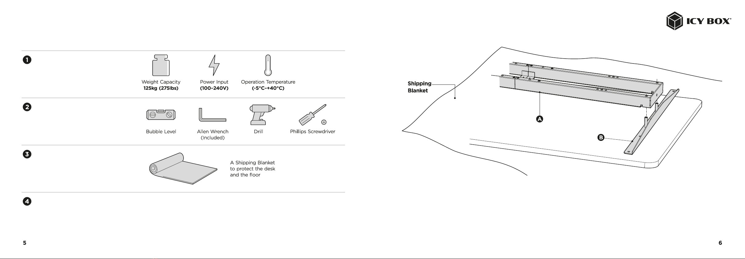
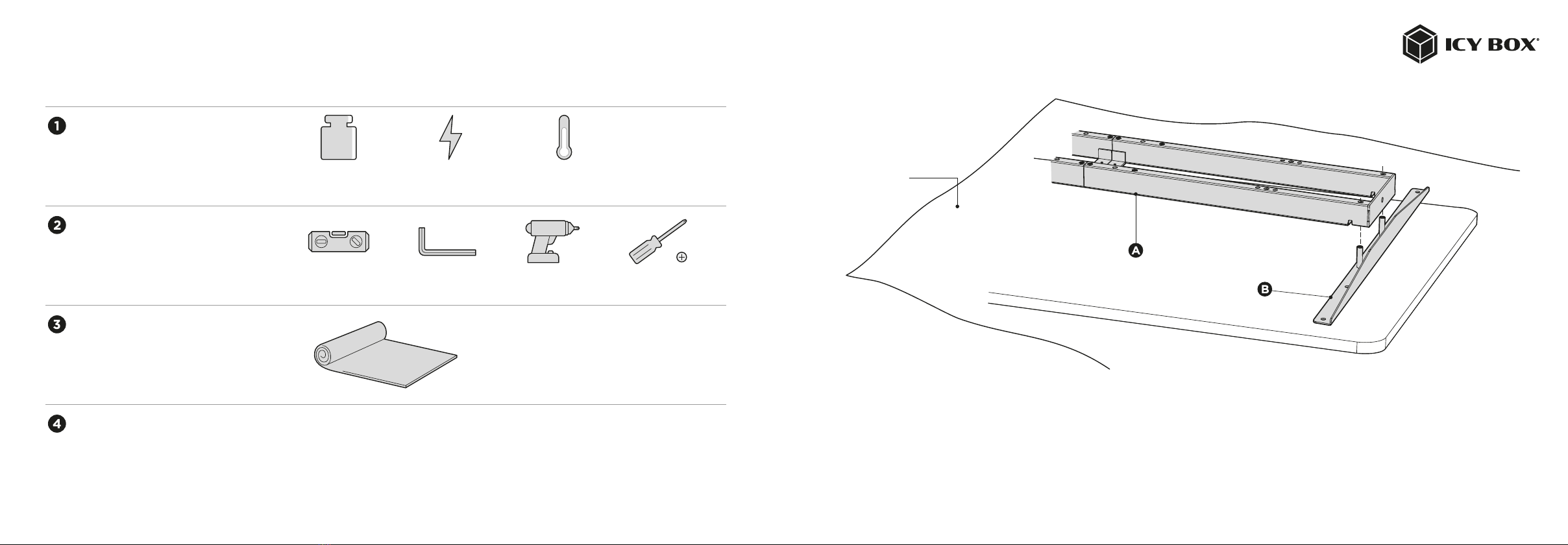
Package content
Preparation Installation
Requirements
Required tools
Recommendation
Note before assembly Please check all of the components shown in the component
checklist. If any of the components are missing or damaged,
contact your point of purchase for a replacement.
Make sure there is enough space for assembly and spread out a blanket if necessary.
• Place the table top (not included in the scope of delivery) carefully with the top side on the blanket.
• Place the crossbar (A) and the side brackets (B) on the tabletop (bottom side).
• Attach the side brackets (B) to the end of the crossbar (A). (No screws are used in this step.)
Note: The drawings of both of the crossbar and side brackets show the backside of the components. Please make sure the crossbar and side brackets keep
facing down while installation, which is convenient for the further steps.

0 ( m i n ) 3 5 ( m a x )
3 5 ( m a x ) 3 0 2 5 2 0 1 5 1 0 5 5 1 0 1 5 2 0 2 5 3 0
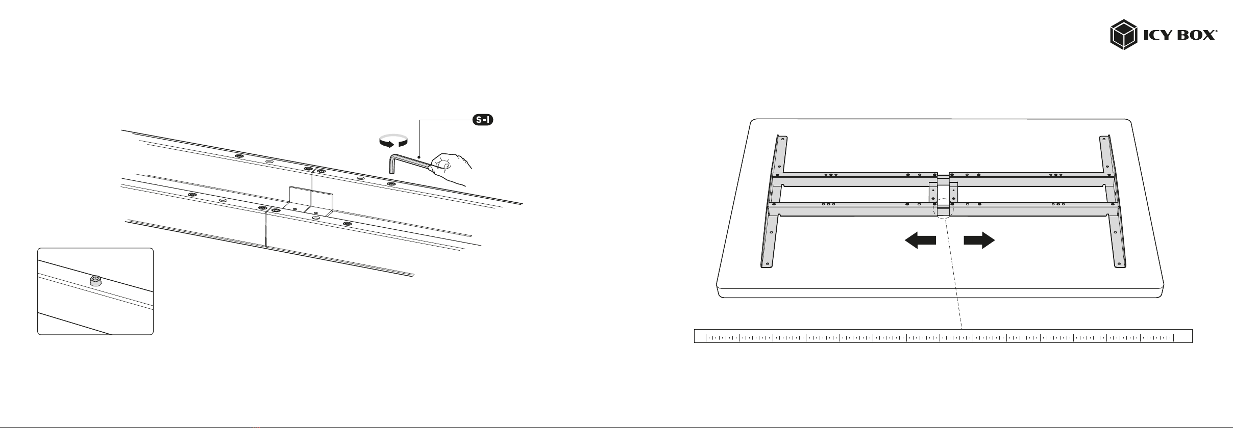
Adjustment of the frame
Loosen the hex head screws (do not unscrew them completely) to
adjust the crossbar and then tighten them again
• Make sure that the frame is positioned in the middle on the tabletop.
• Then adjust the frame to the tabletop (adjustment as described above).
When adjusting the frame, make sure that you do not exceed the marking (silk screen printing on the inner crossbar) on the crossbar

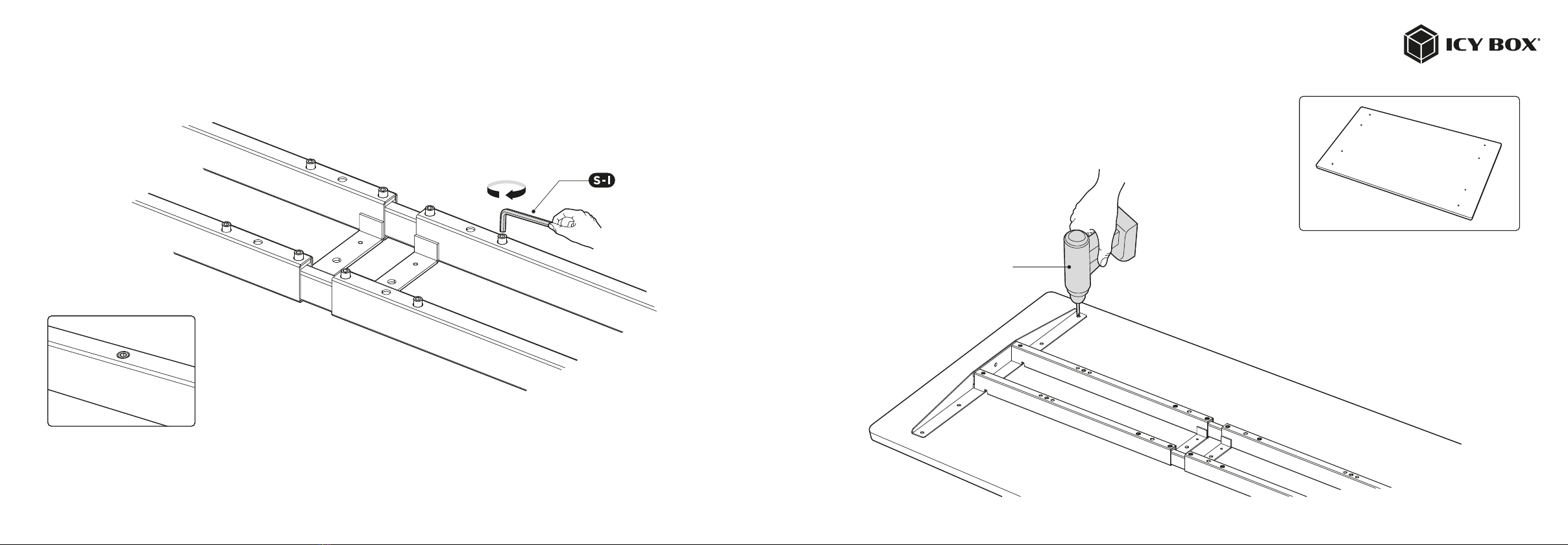
Pre-drilling the mounting holes
Re-tighten all the hex head screws
to complete the adjustment.
Use the cordless screwdriver with a drill to drill guide holes through the side brackets into the
underside of the table top.
Note: The drill holes should be at least 10 mm deep and the drill diameter should be less than 3 mm
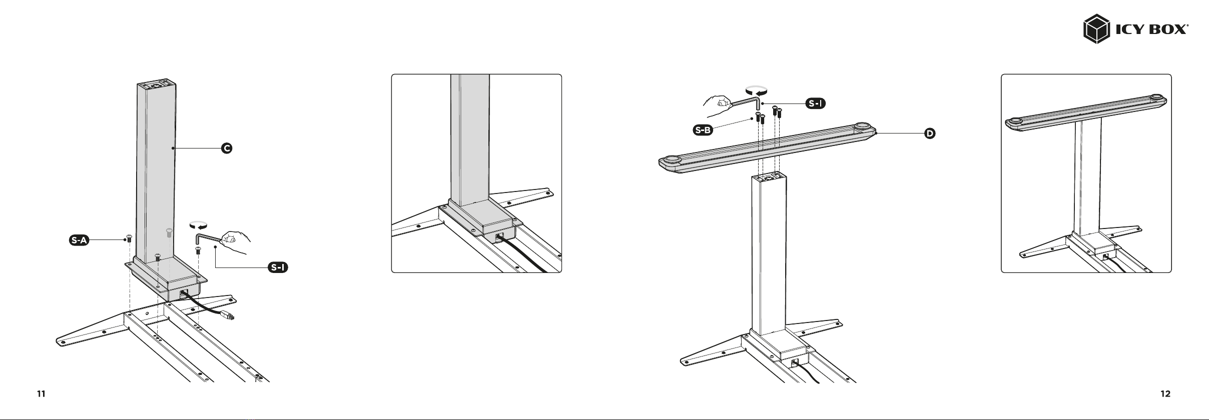
Assembling the feetAssembling the lifting columns
• Insert one lifting column into one end of the crossbar with the head
of the lifting column facing inward. Make sure the mounting holes
on the lifting column completely align with the screw holes on the
crossbar.
• Fix the lifting column (C) to the crossbar using
• the 4 (S-A) screws with the allen wrench (S-1)
• Repeat the same process with a lifting column on the other side.
Place a foot on the bottom of the lifting column. Align the mounting
holes on the foot with the screw holes on the lifting column.
Fix the foot (D) using 4 screws (S-B) with the allen wrench (S-1)
Repeat the same process with the second foot on the other side.

Assembling the fixing plate
The fixing plate can be attached to either the right side
or the left side.
• Align the mounting holes on the fixing plate with the screw holes as shown.
• Attach the fixing plate (E) in the center of the crossbar with 2 screws (S-1) using a Phillips screwdriver.
Note: The arrow on the fixing plate indicates the direction of sliding in the control box. Follow the direction of the
arrow to mount the control box in the next step.
Attaching the control box
• Turn over the desk frame with the crossbar facing up. At least two people are
required when turning over the desk frame. If only one person turns over the
desk frame, serious bodily injuries might occur.
• Connect the cords, control box and motors.
Connect the two motor cords to the two ports marked
"M1" and "M2" (one on each side of the control box).
Connect the controller (J) J cord to the port marked "HS".
Insert the power plug (G) in the port marked "AC".
Note:
• Please make sure the slot on the control box (F) is facing upwards.
There is no corresponding relation between the motor connections
and the lifting columns.
• The illustration of the touch controller is only an example and may
differ from the actual product.

Assembling the cable management tray
• Align the mounting holes of the tray hangers (I) with the screw
holes on the cable management tray.
• Mount the tray hangers to the cable management tray (H) with
the 4 screws (S-F) from below using a Phillips screwdriver.
• The arrow on the fixing plate indicates the direction of sliding in the control box.
Follow the direction of the arrow to mount the control box.
• Slide the control box to the center of fixing plate.
Hang the cable management tray into the
crossbar as shown.

Assembling the desktop
Attach the ten anti-vibration pad (S-H) to the surface of the crossbar at the ten positions as shown.
Tighten the thumbscrews on the tray hangers.

• Align the previously drilled screw holes with the mounting holes on the crossbar. Insert and
tighten the 4 screws (S-C) from below.
• Repeat the same process to assemble the other side of the desktop.
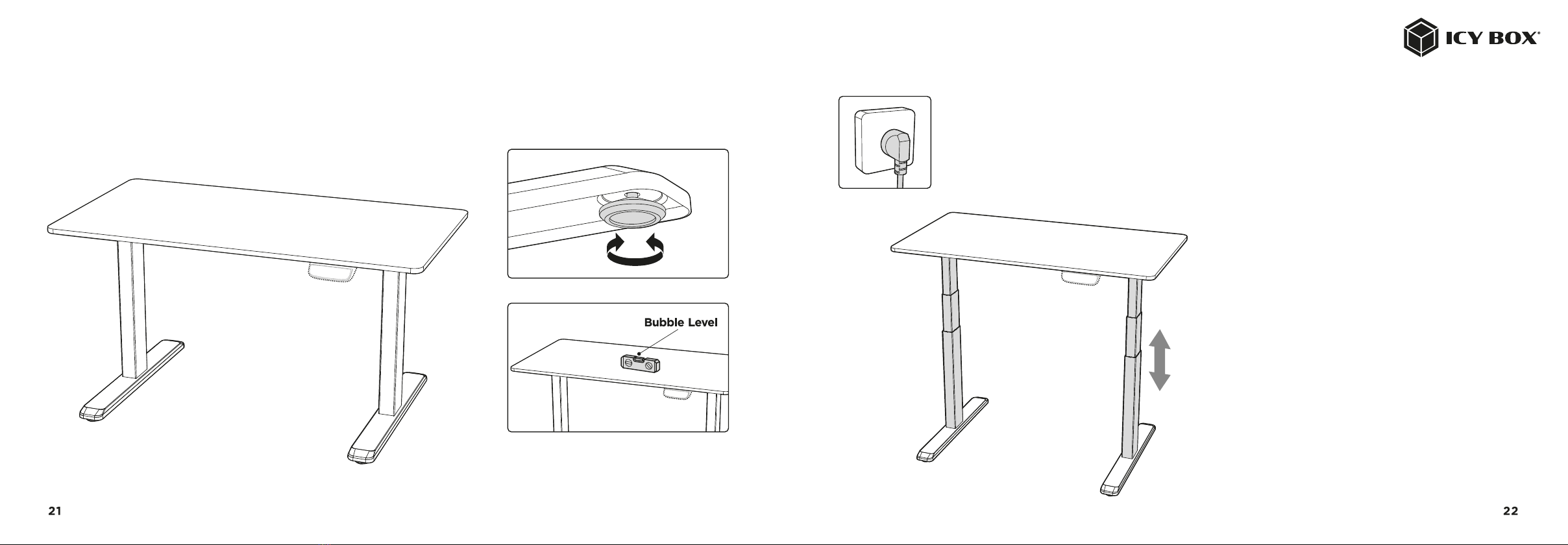
Adjustment
There are two adjustable foot pads under each foot. If the table frame is placed on an uneven
floor, the table frame can be aligned by turning the foot pads.
Tip: Use a bubble level to align the table frame.
Height adjustment
Connect the table frame to the power supply. You
can now use it with the touch controller.
Note: Further instructions for the touch controller
follow directly afterwards.
IB-EW205B-T

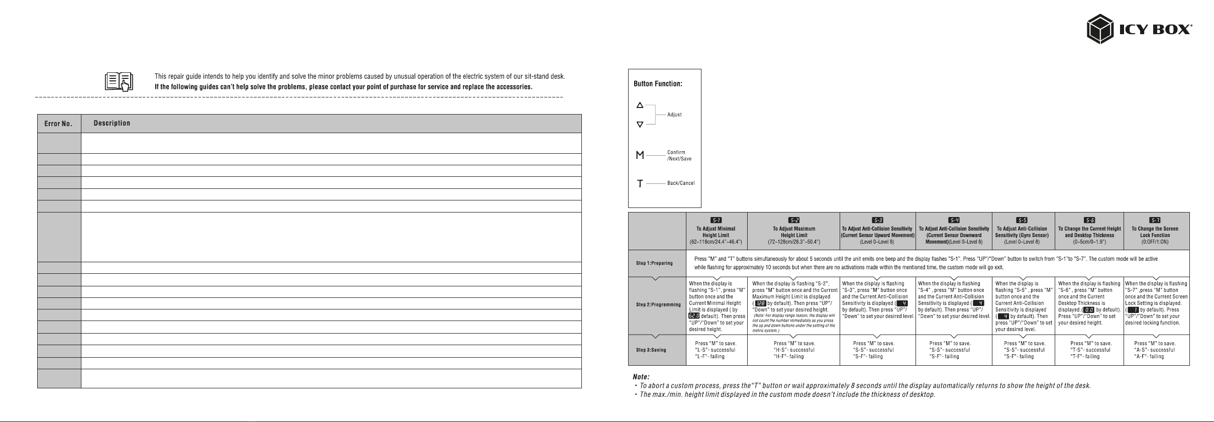
Digital Touch Control Panel
Installation instruction & user guide Reset the system:
• To reset the system, press and hold the “Up” and “Down” buttons simultaneously. The unit emits one beep and the display shows
“ ” and the desk starts moving downward to the lowest position. Do not release the buttons until the unit emits a second beep.
The desk will move upward a little and the display shows the current desk height. The reset process is finished.
Height adjustment:
Press and hold the “UP”/“DOWN” button to lift/lower the desk to your desired height. Press and release the button to lift/lower the desk precisely.
Timer:
• Press the "T" button to set the time at which you want to be reminded to stand up. Each press of the “T” button results in a 0.5 hour increment. The maximum setting for
the reminder time is 2 hours. After setting a time, the display flashes for a few seconds and then automatically shows the height of the table again. The indicator light at
the top right of the control panel lights up.
• 5 beeps sound when the reminder time is reached.
• To deactivate the timer again, press the "T" key repeatedly until the control light in the display goes out again
Memory setting:
• To save altitude settings, press the "M" button and “ ” appears in the display. While the display shows “ ”, press button 1, 2 or 3 to store the corresponding
height position.
• To recall a stored position, press memory button 1, 2 or 3 and the table will move to the desired height. During the "UP and DOWN" movement, the corresponding
height units are shown in the display. To stop the movement, press any key.
Setting up the display lock:
• The display has a lock function so that the current working height is not accidentally adjusted by touching the display.
• To lock the touch controller, press “M” for 3 seconds. As soon as the controller is locked, “ ” is shown in the display and any other operation is invalid.
• To unlock the touch controller, press "M" again for 3 seconds. The display now shows the current height position. 1 minute after the last input, the touch controller is
locked again.
Switch between centimeters and inch:
Press and hold the “T” key for approx. 3 seconds and the current unit of measurement changes to the other.
Energy saving mode:
If no input is made for more than 10 minutes, the touch controller will go into power saving mode and the display becomes dark. Touch any key to reactivate the control panel.
Note: When using the control panel for the first time, please reset the system before any other operation.
23 24
The fixing plate can be attached to either the right side
or the left side.
E01/E07
HOT
E02
E04
E05
E06
E08
E11/E21
E12/E22
E13/E23
E14/E24
E15/E25
E16/E26
E17/E27
E18/E28
E42
E43
Electrical problem has occurred. Plug out the power and re-plug.
System overheating. Stop operating and allow your desk to remain idle for approximately 18 minutes.
The columns don’t go together. Reset the system.
The control panel is disconnected. Check the connection. Plug out the power and re-plug.
Collision avoidance system has activated. Remove all the objects within the range of motion.
Electrical problem has occurred. Plug out the power and re-plug. If it doesn’t work, replace the control box.
- Collision avoidance system has activated. Remove all the objects within the range of motion.
- The control box isn’t placed well. Please make sure the control box is properly attached to the desk frame as the instruction manual or placed well
on the even surface.
- The power cords have pulled the control box. Manage the cables and keep them from pulling the control box.
The motor cords were disconnected, Check the connection or replace the motor cords. E11 corresponds to M1 connector while E21 corresponds to M2 connector.
Electrical problem has occurred. Plug out the power and re-plug. If it doesn’t work, replace the control box.
Motor wires may be broken. Check the connection or replace the motor cords. E13 corresponds to M1 connector while E23 corresponds to M2 connector.
Hall wires may be broken. Check the connection or replace the motor cords. E14 corresponds to M1 connector while E24 corresponds to M2 connector.
Short circuit. Replace the motors or columns. E15 corresponds to M1 connector while E25 corresponds to M2 connector.
Overload leads to the motor to fail to drive. Remove the items from the desktop then reset the system.
Desk move in wrong direction. Check the connection or replace the motor cords. E17 corresponds to M1 connector while E27 corresponds to M2 connector.
Overload has occurred. Remove the items from the desktop.
Memory can not be read. Plug out the power and re-plug. If it doesn’t work, replace the control box.
Collision avoidance system failure. Replace the control box.
Troubleshooting Guide Custom Programming Guide
Before
25 26

Verpackungsinhalt
Traverse Seitenschienen Hubsäulen Füße
Inbusschraube Inbusschraube Kreuzschlitzschraube
Kreuzschlitzschraube Kreuzschlitzschraube Kreuzschlitzschraube
Kabel-Clip Anti-Vibrationsunterlage Inbusschlüssel
Befestigungsplatte Steuergerät
Halter Kabelmanagement Controller
Netzstecker Kabelmanagement
27 28
Die Abbildung des Controllers dient nur als Beispiel.
Das tatsächliche Produkt kann abweichen.
Arbeitsvorbereitung Montage
Vorrausetzung
Benötigte Werkzeuge
Empfehlung
Vor der Montage beachten Bitte überprüfen Sie den Verpackungsinhalt auf Vollständigkeit.
Sollte etwas fehlen, wenden Sie sich bitte unverzüglich an Ihren
Verkäufer.
Eine Transportdecke, um Kratzer und Beschädigun-
gen am Gestell oder Boden zu vermeiden.
Sorgen Sie für ausreichend Platz zur Montage und breiten Sie ggf. eine Decke aus.
• Legen Sie die Tischplatte (nicht im Lieferumfang enthalten) mit der Oberseite auf die Decke
• Setzen Sie die Traverse (A) und die Seitenschienen (B) auf die Tischplatte (Unterseite)
• Befestigen Sie die Seitenschienen (B) an den Enden der Traverse (A). (Bei diesem Arbeitsschritt werden keine Schrauben verwendet).
Hinweis: Die Zeichnungen der Traverse und der Seitenschienen zeigen die Rückseite der Komponenten. Achten Sie darauf, dass die Traverse und die
Seitenschienen bei der Installation nach unten zeigen, was für die weiteren Schritte von Vorteil ist.
Max. Belastung
125 kg
Stromanschluss Betriebstemperatur
(-5°C bis +40°C)
Wasserwaage Inbusschlüssel
(enthalten)
Akkuschrauber
Decke
Kreuzschlitz-
schraubendreher
29 30
0 ( m i n ) 3 5 ( m a x )
3 5 ( m a x ) 3 0 2 5 2 0 1 5 1 0 5 5 1 0 1 5 2 0 2 5 3 0
Einstellung des Rahmens
Lösen Sie die Inbusschrauben (nicht ganz herausdrehen)
zum Verstellen der Hauptschiene und ziehen Sie diese
anschließend wieder fest.
• Stellen Sie sicher, dass der Rahmen in der Mitte auf der Tischplatte positioniert ist.
• Passen Sie den Rahmen an die Tischplatte an (Verstellung wie oben beschrieben).
Achten Sie beim Einstellen des Rahmens darauf, dass Sie die Markierung an der Traverse nicht überschreiten.
31 32
Lorem ipsum
Vorbohren der Befestigungslöcher
Um die Einstellung abzuschließen, ziehen
Sie alle gelösten Inbusschrauben wieder fest.
Verwenden Sie den Akkuschrauber mit einem Bohrer, um Führungslöcher durch die Seitenschienen in die
Unterseite der Tischlatte zu bohren.
Hinweis: Die Tiefe der Bohrlöcher sollte mind. 10 mm und der Bohrerdurchmesser max. 3 mm
betragen.
Akkuschrauber
33 34

Montage der FüßeMontage der Hubsäulen
• Positionieren Sie die Hubsäulen am Ende der Seitenschienen wie
abgebildet. Stellen Sie sicher, dass die Löcher an den Hubsäulen
mit denen der Traverse vollständig übereinstimmen.
• Befestigen Sie die Hubsäulen (C) mit der Traverse. Nutzen Sie 4
(S-A) Inbusschrauben und verwenden Sie zum Festziehen den
Inbusschlüssel (S-1)
• Wiederholen Sie den gleichen Vorgang für die andere Hubsäule.
Setzen Sie den Fuß auf die Hubsäule und richten Sie die Schraubenlö-
cher aufeinander aus.
Befestigen Sie den Fuß (D) mit den 4 Schrauben (S-B), nutzen Sie
dazu den Inbusschlüssel (S-1).
Wiederholen Sie den gleichen Vorgang, um den zweiten Fuß zu
montieren.
35 36

Montieren der Befestigungsplatte
Die Befestigungsplatte kann sowohl auf der rechten als
auch auf der linken Seite angebracht werden.
• Richten Sie die Befestigungslöcher auf der Befestigungsplatte wie abgebildet auf die Schraubenlöcher aus.
• Montieren Sie die Befestigungsplatte (E) mit 2 Schrauben (S-1) mit einem Kreuzschlitzschraubendreher
mittig an der Traverse.
Hinweis: Der Pfeil auf der Befestigungsplatte zeigt die Richtung des Einschiebens des Steuergerätes an. Folgen
Sie der Pfeilrichtung, um den Steuerkasten im nächsten Schritt zu montieren.
Montage des Steuergerätes
• Drehen Sie das Tischgestell mit der Traverse nach oben um. Zum Wenden des
Tischgestells sind mindestens zwei Personen erforderlich. Bei nur einer Person
kann es zu schweren Verletzungen kommen.
• Schließen Sie die Kabel des Steuergerätes an den Motor an.
Schließen Sie die beiden Motorkabel an die beiden mit
"M1" und "M2" gekennzeichneten Anschlüsse an (einer
auf jeder Seite des Steuergerätes).
Schließen Sie das Kabel des Touch-Controllers (J) an
den mit "HS" gekennzeichneten Anschluss an.
Stecken Sie das Netzkabel (G) in den mit "AC"
gekennzeichneten Anschluss.
Hinweis:
• Achten Sie darauf, dass die Führung am Steuergerät (F) nach oben
gerichtet ist. Es gibt keinen Unterschied zwischen den Motoranschlüs-
sen und den Hubsäulen.
• Die Abbildung des Touch-Controllers dient nur als Beispiel und kann
vom tatsächlichen Produkt abweichen.
37 38
Kreuzschlitz-
schraubendreher
Table of contents
Languages:
Popular Indoor Furnishing manuals by other brands

Lightolier
Lightolier Lytespan 8257WH specification

Abbyson
Abbyson Lauren Nailhead Trim Armchair HS-SF-155 Assembly instructions

Schell
Schell Queen Better Life Quick user guide

Alpha Technologies
Alpha Technologies Cordex 12-250W Installation & operation manual

Living Spaces
Living Spaces Reagan RNMR-03-30 Assembly instructions

baby&child
baby&child OGDEN quick start guide


N BROWN
N BROWN Cabana EQ545 Assembly instructions

Humanscale
Humanscale Float installation manual

Morris and Alexander
Morris and Alexander CR-A Fitting & user instructions

Pawleys Island
Pawleys Island Durawood Assembly instructions

Asgard
Asgard VANGARD instructions

Bonaldo
Bonaldo Giotto Assembly instructions