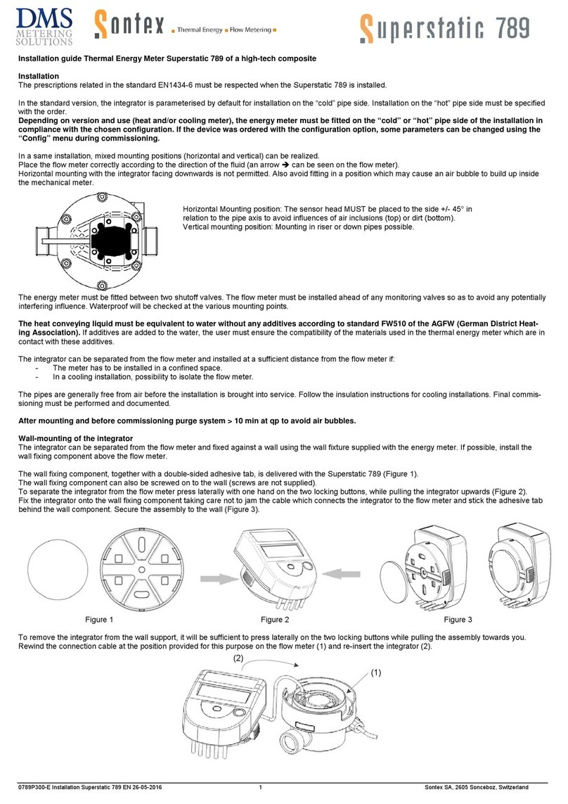
id LAB FOTOMETER 2008 User manual

FOTOMETER 2008 STD
(Light attenuation meter users guide)

2
DEVICE DESCRIPTION .................................................................................................................................... 3
SAFETY RULES................................................................................................................................................... 3
SETTING UP THE DEVICE............................................................................................................................... 3
DISPLAY CONTENT .......................................................................................................................................... 4
OPERATING DEVICE IN AUTOMATIC MODE ........................................................................................... 5
S
WITC ING TO AUTOMATIC MODE
...................................................................................................................... 5
S
WITC ING BACK TO MANUAL MODE
.................................................................................................................. 5
OPERATING DEVICE IN MANUAL MODE .................................................................................................. 5
S
WITC ING TO MANUAL MODE
............................................................................................................................ 5
S
WITC ING BACK TO AUTOMATIC MODE
............................................................................................................. 5
S
WITC ING TO LESS SENSITIVE RANGE
................................................................................................................ 5
S
WITC ING TO MORE SENSITIVE RANGE
.............................................................................................................. 5
USING REFERENCES ........................................................................................................................................ 5
S
ETTING REFERENCE
........................................................................................................................................... 6
USING INPUT FILTER....................................................................................................................................... 6
S
ETTING INPUT FILTER
........................................................................................................................................ 6
DIAGNOSTIC MODES ....................................................................................................................................... 6
S
WITC ING TO DIAGNOSTIC MODE
...................................................................................................................... 6
BASIC MAINTENANCE TASKS....................................................................................................................... 6
R
EPLACING BULB IN T E LIG T SOURCE
............................................................................................................. 6

3
Device description
Light attenuation meter FOTOMETER 2008 consists of modulated light source, lock-
in type light detector and control unit. Device measures intensity of light traveling from the
light source to the light detector. It makes the device suitable for measurement changes of
attenuation of light in the area between the light source and the light detector. Due to
synchronization between light source modulation and the light detector the device is, to some
extent, immune to ambient light and could be operated on normal day light conditions.
The readout of intensity value is in linear arbitrary units (AU) and is not directly
related to any engineering units. The device is intended only for measurement of relative
changes in light intensity.
Device has four decadic ranges and could be operated in two different modes. In
manua mode the ranges must be switched manually by user. In automatic mode the device
itself changes mode when intensity readout goes out of actual range.
The light detector is equipped with two input filters. Fast fi ter provides quick
response but slightly higher noise and is intended for measurement of unstable, changing light
intensity. For measurement in stable, balanced conditions might be done using s ow fi ter
which reduces noise but has very long settling time (up to one minute).
Safety rules
The control unit is powered by 230V AC which might be dangerous to life. Never remove the
cover of control unit when the mains electricity is connected. Mains plug MUST be always
removed before unscrewing the cover. Any service must be provided by a qualified electrician
only.
Device may be operated only in room environment between 15 and 40 C with non condensing
humidity. When moving device from cold environment to room temperature always allow the
device temperature to accommodate to room environment to avoid moisture to condensate on
the device before switching the device on.
Setting up the device
Mount control device to its place, preferably a 19 inch rack case. Connect 15 pin cable
between the control unit and the detector and 25 pin cable between the control unit and the
light source. Double check that cables are connected properly according to labels on control
unit. Connect mains electricity and switch the device on.
The light source and light detector must be mounted in such position that light source
outlet is facing the light detector inlet directly. The light beam must go through the area where
the light attenuation should be measured. Make sure that axes of light source outlet and light
detector inlet are perfectly parallel. Using small piece of paper make sure that the light beam
is aimed directly to the center of light detector inlet.

4
Display content
Display on control unit shows measured light intensity value as well as other related
information like actual range, measurement mode, selected input filter and so on. The layout
of the display is described in the table below.
Switching status Mode
Overflow status Range number
Intensity value Reference 1 Reference 2 Diagnostic mode
Range [dB] [dB] Filter
Meaning of display messages is described bellow.
Disp ay fie d Possib e va ues Description
SWITC ING Device is switching between ranges.
Intensity value is not valid at the moment.
Switching status
<blank> Device is not switching range.
OVERFLOW Light detector is saturated by ambient light
or too strong signal from light source. .
Intensity value is not valid at the moment.
Overflow status
<blank> Light detector is not in overflow condition.
Intensity value <value in AU> Actual value of intensity in AU. Selected
range is already taken into account.
Range 100 Selected range 0..100 AU (most sensitive)
Range 1000 Selected range 0..1000 AU
Range 10000 Selected range 0..10000 AU
Range
Range 100000 Selected range 0..100000 AU (less sensitive)
Reference 1 <value in dB> Relative change in intensity since the
reference 1 was set expressed in dB.
Reference 2 <value in dB> Relative change in intensity since the
reference 2 was set expressed in dB.
AUTO Device is in automatic mode. Mode
MANUAL Device is in manual mode.
RANGE 0 Selected range 0 (0..100 AU)
RANGE 1 Selected range 1 (0..1000 AU)
RANGE 2 Selected range 2 (0..10000 AU)
Range number
(according to codes used
when operating device
from remote computer) RANGE 3 Selected range 3 (0..100000 AU)
<blank> Device is in standard measurement mode.
DIAG ZERO Device is in diagnostic mode ZERO.
DIAG FULL Device is in diagnostic mode FULL SCALE.
DIAG NEG Device is in diagnostic mode NEGATIVE
FULL SCALE.
Diagnostic mode
DIAG CMR Device is in diagnostic mode COMMON
MODE REJECTION.
FILTER SLOW Slow input filter selected. Filter
FILTER FAST Fast input filter selected.

5
Operating device in automatic mode
In automatic mode the device switch to more sensitive range, when intensity value decrease
below 8 percent of current range. When intensity rise over 100 percent of current range,
device automatically switches to less sensitive range.
During switching device displays SWITC ING message on the display. During this
period the intensity readout is not valid. On some conditions (slow filter selected, large
sudden change in intensity) the intensity might not be settled when SWITC ING message
disappear and additional waiting for valid value might be necessary.
Switching to automatic mode
While in manual mode, press AUTO/MANUAL button to switch to automatic mode.
Switching back to manual mode
While in automatic mode you can press AUTO/MANUAL button to switch back to manual
mode. By pressing RANGE+, RANGE- or DIAG while in automatic mode you switch back
to manual mode as well.
Operating device in manual mode
In manual mode, ranges must be switched manually by the user. When range is manually
switched, device displays SWITC ING message and goes through the switching procedure in
same manner as in automatic mode.
Switching to manual mode
While in automatic mode you can press AUTO/MANUAL button to switch to manual mode.
By pressing RANGE+, RANGE- or DIAG while in automatic mode you switch to manual
mode as well.
Switching back to automatic mode
While in manual mode, press AUTO/MANUAL button to switch to automatic mode.
Switching to less sensitive range
To switch to less sensitive range press RANGE- button.
Switching to more sensitive range
To switch to more sensitive range press RANGE+ button.
Using references
To compute light attenuation directly during measurement there are two user references
available. When reference is set it displays the ratio between reference value and current value
in a logarithmic scale in dB. The value in logarithmic scale is computed using following
formula:
⋅= ][Re
][
log10][ AUvalueference
AUvalueIntensity
dBvalueLog

6
Setting reference
To set reference press SET button bellow the reference you want to set. Current intensity
value is stored as reference value.
Using input filter
Light detector has two input filters. Fast filter is intended for measurement of values
changeable in time. It provides fast response with slightly increased noise level. Slow filter
suppress noise but has rather slow response time. Thus it is suitable for measurement of in
stable conditions when light intensity does not change fast.
Setting input filter
To adjust input filter press the FILTER button. The filter will toggle from slow to fast and
vice versa with every pres of the button.
Diagnostic modes
The device provides four diagnostic modes which are useful for troubleshooting. The
diagnostic modes are: zero offset, full scale, negative full scale, common mode rejection.
Mode Description
Zero offset Both differential inputs of A/D converter are switched to ground.
Full scale Negative input of A/D converter is grounded. Positive is switched
to the voltage reference.
Negative full scale Positive input of A/D converter is grounded. Negative is switched
to the voltage reference.
Common mode rejection Both differential inputs of A/D converter are switched to voltage
reference.
Switching to diagnostic mode
To switch to diagnostic mode press DIAG button. First diagnostic mode is selected. With
every consecutive press of DIAG button device will switch to next diagnostic mode. After
last diagnostic mode the device switch back to normal measurement mode.
While in diagnostic mode you can switch to normal measurement mode anytime by pressing
RANGE+, RANGE- or AUTO/MANUAL buttons.
Basic maintenance tasks
Replacing bulb in the light source
To replace the bulb in the light source follow the steps described bellow.
• Switch off the device.
• Disconnect cable between control unit and the light source.
• Remove four screws on the back cover of the light source using Philips screwdriver.
• Carefully remove the back cover together with cylindrical side cover.
• Disconnect internal connector so you can completely remove back and side cover.
• Remove four screws which hold the bulb assembly and remove bulb assembly.
• Loosen screws holding the bulb in place and remove old bulb.
• Install new bulb in the same position as the original and tighten screws.
• Put bulb assembly back to its place and fasten it by four screws.

7
• Attach connectors back to its place. Be careful not to swap two same size connectors.
One marked as MOTOR connect to the chopper motor. Other connectors can not be
swapped.
• Slide the cylindrical side cover and the back cover to its place and fasten it using four
screws.
Table of contents
Other id LAB Measuring Instrument manuals
Popular Measuring Instrument manuals by other brands
Klein Tools
Klein Tools RT390 instruction manual

HAZ-DUST
HAZ-DUST HD-1100 instructions
Thermo Scientific
Thermo Scientific NanoDrop OneC user guide

Endress+Hauser
Endress+Hauser QG2000 Technical information and operating instructions
Emerson
Emerson ControlWave EFM instruction manual
Keithley
Keithley 6485 instruction manual

