USA Measurements US-4011 User manual

US-4011 Indicator
User / Technical Manual
Contents subject to change without notice
Version 1.0

US-4011 . 1 .
07/2017

TABLE OF CONTENTS
1.
INTRODUCTION
..................................................................................................................... 1
1.1. Safety Precautions ......................................................................................................................... 1
1.2. Specification ................................................................................................................................. 1
2.
INSTALLATION
...................................................................................................................... 3
2.1. Contents ..................................................................................................................................... 3
2.2. Connection types: ........................................................................................................................... 3
3.
OVERVIEW OF CONTROLS AND FUNCTIONS
.................................................................................... 4
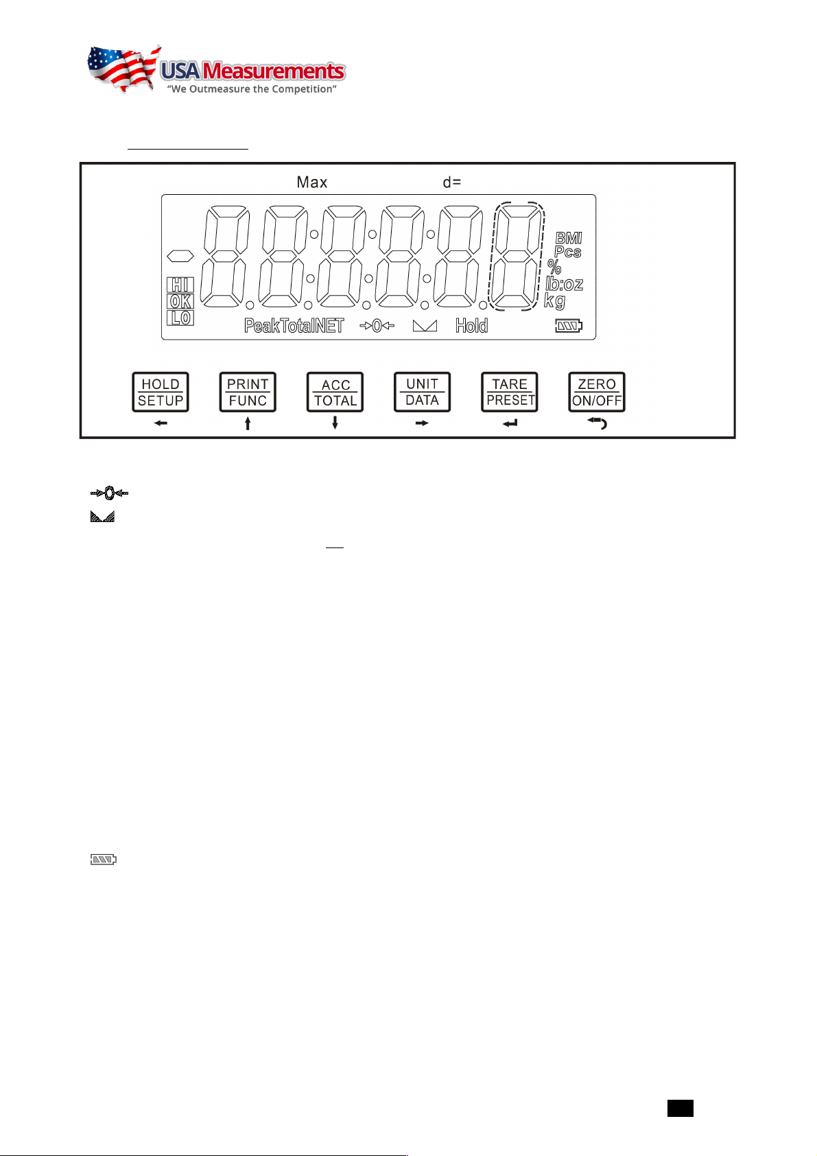
3.1. Indicator Display Character Definitions .................................................................................................. 4
3.2. Indicator Display ............................................................................................................................ 5
4.
Operation Menu Structure
........................................................................................................ 7
4.1. Enter Setup Mode .......................................................................................................................... 7
4.2. Main menu: .................................................................................................................................. 7
4.3. CONFIG Submenu: .......................................................................................................................... 7
4.4. USER Submenu: ........................................................................................................................... 10
4.5. CAL Submenu: ............................................................................................................................. 14
4.6. MISC Submenu: ........................................................................................................................... 15
4.7. TEST Submenu: ........................................................................................................................... 15
5.
OPERATION:
....................................................................................................................... 16
5.1. Normal Weighing Mode .................................................................................................................. 16
5.2. Count Weighing Mode: ................................................................................................................... 18
5.3. Percent Weighing Mode: ................................................................................................................. 20
5.4. BMI Working Mode: ....................................................................................................................... 21
5.5. HOLD Function: ........................................................................................................................... 21
5.6. Accumulation: ............................................................................................................................. 23
5.7. Weight Fine-tune: ......................................................................................................................... 23
6.
Calibration:
........................................................................................................................ 25
7.
MISC and TEST operation
....................................................................................................... 28
7.1. Display ADC output Code ................................................................................................................ 28
7.2. Display and Calibrate Power Voltage ................................................................................................... 28
7.3. Display and Set Time ..................................................................................................................... 29
7.4. Display and Set Date ..................................................................................................................... 29
7.5. Display Firmware Version ................................................................................................................ 29
7.6. Display Test ................................................................................................................................ 29
7.7. Keyboard and Buzzer Test .............................................................................................................. 29
7.8. Serial Port1/2 (COM1/2) Receiving Test .............................................................................................. 29
7.9. Serial Port1/2(COM1/2) Transmitting Test ............................................................................................ 30
8.
Details about Serial Communication:
.......................................................................................... 31
9.
Connectors and Jumpers:
....................................................................................................... 36
10.
Meaning of Some Symbols and Troubleshooting:
........................................................................ 38

US-4011 . 1 .
1.
INTRODUCTION
This manual contains installation, operation and maintenance instructions for the US-4011 indicators. Please read this
manual completely before installation and operation.
1.1.
Safety Precautions
For safe and dependable operation of this equipment, please comply with the following safety precautions:
l Verify that the input voltage range printed on the data label matches the local AC power to be used.
l Make sure that the power cord does not pose a potential obstacle or tripping hazard.
l Use only approved accessories and peripherals.
l Operate the equipment only under ambient conditions specified in these instructions.
l Disconnect the equipment from the power supply when cleaning.
l Do not operate the equipment in hazardous or unstable environments.
l Do not immerse the equipment in water or other liquids.
l Service should only be performed by authorized personnel.
NOTE: Some functions maybe disabled by manufacture before shipping, if you need these functions or don’t want to
use some other functions, please contact with manufacture in advance, because of this, some operations or faceplate
maybe are a little bit different, and some description sections may be deleted.
1.2.
Specification
Model
US-4011
Max Display Range
-999,999 to 999,999
Max Display Resolution
1:100,000 (primary unit)
1:125,000 (second unit)
Max Approved Resolution
1/5000 (NTEP/MC), 1/3000 (OIML)
Division
0.0001,0.0002,0.0005------10,20,50
Calibration Unit
kg or lb
Weighing Unit
kg, lb, lb:oz, g, oz, pcs, %
Display
6-digit, 7-segment, 1" (25mm) LCD with blue backlight
Accuracy
≤0.01%
Power supply
Alkaline Batteries: 4 x “AA” size cells
AC Adapter: 6Vdc/500mA, with central positive
USB
Work current
≤15mA (with backlight off, no load cells)
≤30mA (with backlight on, no load cells)
≤50mA (with backlight on and one 350 load cell)
Functions
Normal weighing, Counting, Percent weighing, Check weighing, BMI, Hold, Accumulation
Zero Range
Programmable zero range
Tare Range
Full capacity
Stabilization Time
<3 seconds

US-4011 . 2 .
Model
US-4011
Keypad
HOLD/SETUP , PRINT/FUNC, ACC/TOTAL/TOTAL, UNIT/DATA, TARE/PRESET , ZERO/ON/OFF
Operating Temperature
15° to 105°F (-10° to 40°C)
Humidity Range
<90% relative humidity, non-condensing
Load Cell Excitation Voltage
5V DC
Load Cell Drive
-3mV/V to 3mV/V
Recommended actual scale
interval (d)
>1uV/ display division
Max Load Cell Excitation
60mA (can power 4-350 ohm bridge)
Signal Connection
4 or 6 lead with sense leads
Analog Circuit characters
l 24-bit A/D converter;
l Conversion Speed: 10Hz or 80Hz;
l Input range: -15mV to +15mV;
l Output code: 1mV input between S+ and S- of load cell connector will output about
100,000 raw Counts;
l With Hardware low pass filter and 2 programmable digital low pass filters
Interface
l Serial port1: Full-duplex RS232
l Serial port2: USB (Virtual RS232)
l Optional Serial port3: Bluetooth
Calibration Method
l Software calibration with long-term storage in EEPROM;
l Provides smooth curve fit through four points;
l Calibration can be done under kg or lb weight unit with 10% -100%FS standard weight
Real Clock
built-in nonvolatile real time & date
Dimensions
(L x W x H)
With bracket: 9.8" x 4.9" x 2.8" (250mm x 125mm x70mm)
Without bracket: 7.9" x 3.7" x 1.8" (200mm x 95mm x 45mm)
Net weight
0.95kg

US-4011 . 3 .
2.
INSTALLATION
2.1.
Contents
§ Indicator with bracket
§ User & Technical manual
§ Sealing lead
§ Batteries (option)
§ AC adapter
§ RS232 communication cable(option)
§ USB communication cable(option)
2.2.
Connection types:
7 pins socket used:
Pin1:
Excitation +
Pin2:
Sense +
Pin3:
Signal +
Pin4:
Excitation –
Pin5:
Sense –
Pin6:
Signal -
Pin7:
Shield
(7 pins socket)
Base
(7 holes socket)
Indicator

US-4011 . 4 .
3.
OVERVIEW OF CONTROLS AND FUNCTIONS
3.1.
Indicator Display Character Definitions

US-4011 . 5 .
3.2.
Indicator Display
3.2.1.
Meaning of symbol on faceplate:
§ - Scale is zeroed, gross weight is 0, tare is 0.
§ - Scale is stable.
§
NET
- Display reading is net weight; tare is not 0.
§
Total
- Display data is accumulated total times, weight, pieces, or percentage.
§
Hold
- Scale is in dynamic weighing mode.
-
Hold
flashes - actual fluctuating weight displayed.
-
Hold
does not flash - locked weight is displayed.
§
Peak
- Scale is in dynamic weighing mode. Hold type is PEAK-HOLD.
§
BMI
- Scale is working in BMI mode
§
lb
- Measure unit is lb or lb:oz
§
oz
- Measure unit is oz or lb:oz
§
kg
- Measure unit is kg
§
g
- Measure unit is g
§
% -
Measure unit is % (in percentage weighing mode).
§
Pcs
- Measure unit is pieces (in counting mode).
§ - Battery level.
§
HI
- Data compare (check-weighing) is enabled. Current data (weight, pieces, or percent) is above the specified
upper limit.
§
OK
- Data compare is enabled. Current data is between the specified upper and lower limits.
§
LO -
Data compare is enabled. Current data is below the specified lower limit.

US-4011 . 6 .
3.2.2.
Summary of Key function
KEY
MODE
DEFINITION
SETUP
Weighing,
Counting, or
Percent mode
<3 seconds
Enters or exits
HOLD
mode
>3 seconds
Enters
SETUP
mode
Input data mode
<3 seconds
Returns to last sub-menu
>3 seconds
Inputs decimal point
Menu selection mode
Returns to last sub-menu
PRINT
FUNC
Weighing,
Counting, or
Percent mode
<3 seconds
Sends output data via the serial port
>3 seconds
Selects mode: Weighing, Counting, or Percent
Input data mode
Increases the digit in the flashing data entry position by one
Menu selection mode
Returns to last item of current sub-menu
ACC
TOTAL
Weighing,
Counting, or
Percent mode
<3 seconds
Adds accumulation values to memory; displays instances and totals
>3 seconds
Displays accumulation instances and totals
Input data mode
Decreases the digit in the flashing data entry position by 1
Menu selection mode
Goes to next item of current sub-menu
UNIT
DATA
Weighing mode
<3 seconds
Changes weighing unit of measure
Counting or
Percent mode
<3 seconds
Enters the submenu to input piece weight for counting or to enter
reference weight for percent-weighing
Weighing,
Counting, or
Percent mode
>3 seconds
Enters the submenu to input the comparative data range for
check-weighing
Time or Date mode
>3 seconds
Enters time or date setting mode
Input data mode
Shifts the flashing data entry position from right to left
Display ADC code
Select displaying code from no-filter, filter1, filter2
Menu selection mode
Goes to next item of current sub-menu
TARE
PRESET
Weighing,
Counting, or
Percent mode
<3 seconds
Tare the weight
>3 seconds
Enters pre-determined tare input mode
Input data mode
Confirms the input data and forwards to next step
Menu selection mode
Confirms the input data and forwards to next step
ZERO
ON/OFF
Power Off
Powers on
Weighing,
Counting, or
Percent mode
<3 seconds
Zeros the platform weight
>3 seconds
Powers off
Input data mode
Ignores the modification
Menu selection mode
Exits from current working mode
Note:
Normally, the second function of one key need pressing it down more than 3s.

US-4011 . 7 .
4.
Operation Menu Structure
4.1.
Enter Setup Mode
4.1.1. If need to set configuration parameters, set user parameters, calibrate the scale, set current date or time, test
some hardware… It’s need to long press
HOLD/SETUP
key to enter setup mode
4.1.2. After Entering Setup Mode, the main menu item
CONFIG
will be shown first.
4.1.3. In Setup mode, use keys to select wanted submenu item, and select wanted
choice, set wanted number, confirm and save data, or exit this mode.
4.2.
Main menu:
4.3.
CONFIG Submenu:
CONFIG
SubMenu1
SubMenu2
Option
Default
Remark
Final set
CFG.ON
CFG.OFF
ON
Seal switch is on or off
RESET
NO
NO
Reset configure parameters to factory setting
YES
REGULA
NONE
NONE
Select the standard that the scale will comply with:
USA,CANADA, EUROPE
USA
CANADA
EUROPE
PRIM.N
100-
100000
3000
The division number under primary unit, if
(REGULAR)≠none, the max is 10,000
PRIM.D
0.0001
1
The division value under primary unit; the division
value under second unit is automatically
determined by indicator according to the division
value under primary unit.
0.0002
0.0005
0.001
0.002
0.005
0.01
0.02
0.05
0.1
0.2
0.5
1
2
5
10
20
50
PRIM.Ut
KG
KG
Select the primary unit from kg or lb; defaulted
calibration standard weight unit is the primary unit.
KG
LB

US-4011 . 8 .
SECND.N
100-
125000
3000
The division number under second unit, the max
is 1.25*(PRIM.N).
if(REGULAR)≠none, the max is 10,000
SubMenu1
SubMenu2
Option
Default
Remark
Final set
10N.DSP
NO
NO
Display weight at 10 times division number under
primary unit. if (REGULAR)=none, no this item
NO
YES
MOTION
1-255
4
Check motion window:
1-255
=±0.25d *(1-255),
if (REGULAR)≠none, the max is 12
4
OVER.LD
0-100
0
Over load display limitation:
0
=FS+9d;
1-100
=101%FS -200%FS,
if (REGULAR)≠none, the max is 10
0
AD.FROM
ADC
ADC
Data of ADC comes from:
ADC
=local A/D chip on PCB;
COM3
=COM3 interface;
ADC
COM3
AD.H.SPD
NO
NO
Speed of A/D convert:
NO
=10Hz;
YES
=80Hz;
if AD.FROM=COM3,this item will not be shown
NO
YES
UNITS
KG
YES
YES
Units that can be used by UNIT key select:
YES
=enable this unit to be used;
NO
=disable this unit to be used;
Refer to table5-1 and table5-2.
For legal-for-trade application, lb:oz is not
allowed.
YES
NO
LB
YES
YES
YES
NO
OZ
YES
NO
NO
NO
LB
OZ
YES
NO
NO
NO
G
YES
NO
NO
NO
ZRO.PNT
IZSM
0-100
10
Initial zero(power on zero) point range:
0
=no limitation;
1-100
= (calibration zero point) ±1%FS
~(calibration zero point) ±100%FS, If
(REGULAR)≠none, the max is 10
10
IN.IZSM
WEIGHT
WEIGHT
Choose which weight as current initial zero
point when current weight is in IZSM range:
WEIGHT
= current weight ;
CAL.ZRO
= calibration zero;
LAST.Z.T
=switch-off zero and tare
If (REGULAR)≠none, the value is fixed on WEIGHT
N.A
CAL.ZRO
LAST.Z.T
OV.IZSM
DSP.OVR
DSP.OVR
Choose which weight as current initial zero
point when current weight is over IZSM range:
DSP.OVR
=display initial zero is over;
WEIGHT
= current weight;
CAL.ZRO
= calibration zero;
LAST.Z.T
=switch-off zero and tare
If (REGULAR)≠none, the value is fixed on
DSP.OVR
N.A
WEIGHT
CAL.ZRO
LAST.Z.T

US-4011 . 9 .
SAZSM
0-100
2
Zero key range:
0
=no limitation;
1-100
= (initial zero point) ±1%FS~(initial zero
point) ±100%FS,
if (REGULAR)≠none, the max is 2
2
SubMenu1
SubMenu2
Option
Default
Remark
Final set
ZRO.PNT
AZSM
0-100
8
Zero tracking window:
0
=0d, no tracking;
1-100
=±(0.2+0.05*(1-100))d /s, if
(REGULAR)≠none, the max is 10
8
FILTER
FLT1.TH
0-255
40
Enter digital filter1 threshold:
0
=no filter1;
1-254
=filter1 be used only when vibration in
±0.25d*(1-254) ;
255
= filter1 be always used
40
FLT1.ST
1-64
8
Digital filter1 intensity:
1-64
ADC’s data will be averaged
8
FLT2.TH
0-255
8
Enter digital filter2 threshold:
0
=no filter2;
1-254
=filter2 be used only when vibration in
±0.25d*(1-254) ;
255
= filter2 be always used
8
FLT2.ST
0-255
240
Digital filter2 intensity:
0-255
=weak to strong
240
FUNC
HOLD
YES
YES
Yes/No
=enable/disable hold function;
no
NO
COUNT
YES
YES
Yes/No
=enable/disable counting function.
no
NO
PERCNT
NO
100.0%
Percent weighing function is enable or disable:
NO
=disable;
100%
=enable and display format is 100% ;
100.0%
=enable and display format is 100.0%;
100.00%
=enable and display format is 100.00%;
100.0%
100%
100.0%
100.00%
BMI
YES
NO
Yes/No
=enable/disable BMI function,
NO
NO
COMPAR
YES
YES
Yes/No
=enable/disable data comparison
function;
YES
NO
ACCUMU
NO
MANUAL
Accumulation Mode selection:
NO
=no accumulation function;
MANUAL
=add up current number to accumulation
memory after TATOL key is pressed;
AUTO
=automatically add up current number to
accumulation memory after scale is stable and
weight is over (NLD.RNG)
MANUAL
MANUAL
AUTO
GEO.CAL
YES
YES
Yes/No
=enable/disable Geographical Adjustment
Factor
YES
NO
WT.ADJ
YES
N.A
Yes/No
=enable/disable weight fine-tuning using
keypad in weighing mode, if (REGULAR)≠none,
this item is N.A.
N.A
NO
* The setting will be limited by choice of REGUALA

US-4011 . 10 .
4.4.
USER Submenu:
USER
SubMenu1
SubMenu2
Option
Default
Remark
Final set
RESET
NO
NO
NO
Reset user parameters to factory setting
NO
YES
COM1
BAUD.RT
1200
9600
Selection of com1's
baud rate
9600
2400
4800
9600
19200
38400
BYT.FMT
8N1
8N1
Selection of com1's byte format:
8N1
=8 data bits, No parity check bit, 1 stop bit;
7O1
=7 data bits, 1 Odd parity check bit, 1 stop bit;
7E1
=7 data bits, 1 Even parity check bit, 1 stop bit;
7O2
=7 data bits, 1 Odd parity check bit, 2 stop bit;
7E2
=7 data bits, 1 Even parity check bit, 2 stop bit;
8N1
7O1
7E1
7O2
7E2
OUT.MOD
NONE
PRTCMD
Selection com1 output mode:
NONE
=No communication;
CONT
=continuously output;
PRINT
=output after PRINT key pressed;
CMD
=output after a request command is received;
PRT.CMD
= output after PRINT key pressed or request
command received;
STABLE
=output after scale is stable;
Note:
use PRINT or CMD to output data, the scale must
be stable.
CONT
CONT
PRINT
CMD
PRTCMD
STABLE
LAYOUT
MULTPL
MULTPL
Com1 output content and format set:
MULTPL
= the following selected item in OUT1 will be
output use defined format;
SINGLE
= only displayed content and current status will
be output, it’s compatible with NCI-SCP01;
EH-SCP
= Command –response mode;
SCP-12
= only displayed content and current status will
be output, it’s compatible with NCI-SCP12(NCI3835);
SINGLE
SINGLE
EH-SCP
SCP-12
OUT1
SCAL.ID
YES
NO
Yes/No
=enable/disable output scale's ID number,
Prompt is “SCALE ID”
NO
NO
GROSS
YES
NO
Yes/No
=enable/disable output gross weight. Prompt is
“GROSS”
NO
NO
TARE
YES
NO
Yes/No
=enable/disable output tare weight. Prompt is
“TARE”
NO
NO
NET
YES
YES
Yes/No
=enable/disable output net weight. Prompt is
“NET”
YES
NO
PERCNT
YES
NO
Yes/No
=enable/disable output weight percentage.
Prompt is “PERCENTAGE”
NO
NO
UPCTWT
YES
NO
Yes/No
=enable/disable output weight of 1%
percentage. Prompt is “1% REF WT”
NO
NO
COUNT
YES
NO
Yes/No
=enable/disable output counts. Prompt is
“QUANTITY”
NO
NO

US-4011 . 11 .
SubMenu1
SubMenu2
Option
Default
Remark
Final set
OUT1
PCWT
YES
NO
Yes/No
=enable/disable output piece weight. Prompt is
“PIECE WT”
NO
NO
BMI
YES
NO
Yes/No
=enable/disable output height and BMI. Prompt
is “HEIGHT” and “BMI”
NO
NO
ACCUMU
YES
NO
Yes/No
=enable/disable output accumulation times and
total. Prompt is “ACC. N” and “TOTAL”
NO
NO
DATE
YES
NO
Yes/No
=enable/disable output date. Prompt is “DATE”
NO
NO
TIME
YES
NO
Yes/No
=enable/disable output time. Prompt is “TIME”
NO
NO
AD.CODE
YES
NO
Yes/No
=enable/disable output ADC's code. Prompt is
“A/D CODE”
NO
NO
BAT.VOL
YES
NO
Yes/No
=enable/disable output voltage of battery.
Prompt is “VOLTAGE”
NO
NO
STATUS
YES
NO
Yes/No
=enable/disable output scale's status. Prompt is
“STATUS”
NO
NO
B.LINE
NONE
LINE1
How many blank lines after strings output:
NONE
=no blank line;
LINE1/2/3/4
=there're 1, 2,3 or 4 blank lines after
strings, used for paper feed forward 1/2/3/4 lines.
LINE1
LINE1
LINE2
LINE3
LINE4
COM2
BAUD.RT
1200
9600
selection of com2's
baud rate
4800
2400
4800
9600
19200
38400
BYT.FMT
8N1
8N1
selection of com2's byte format:
8N1
=8 data bits, No parity check bit, 1 stop bit;
7O1
=7 data bits,1 Odd parity check bit, 1 stop bit;
7E1
=7 data bits,1 Even parity check bit, 1 stop bit;
7O2
=7 data bits,1 Odd parity check bit, 1 stop bit;
7E2
=7 data bits,1 Even parity check bit, 2 stop bit;
7E1
7O1
7E1
7O2
7E2
OUT.MOD
NONE
PRT.CMD
Selection com2 output mode:
NONE
= No communication ;
CONT
=continuously output;
PRINT
=output after PRINT key pressed;
CMD
=output after a request command is received;
PRT.CMD
= output after PRINT key pressed or request
command received;
STABLE
=output after scale is stable;
Note: use
PRINT
or
CMD
to output data, the scale must
be stable.
PRT.CMD
CONT
PRINT
CMD
PRT.CMD
STABLE
LAYOUT
MULTPL
MULTPL
Com2 output content and format set:
MULTPL
= the following selected item in OUT2 will be
output use defined format;
SINGLE
= only displayed content and current status will
be output, it’s compatible with NCI-SCP01;
EH-SCP
= Command –response mode;
SCP-12
= only displayed content and current status will
be output, it’s compatible with NCI-SCP12(NCI3835);
SCP-12
SINGLE
EH-SCP
SCP-12

US-4011 . 12 .
SubMenu1
SubMenu2
Option
Default
Remark
Final set
OUT2
SCAL.ID
YES
NO
Yes/No
=enable/disable output scale's ID number,
Prompt is “SCALE ID”
NO
NO
GROSS
YES
NO
Yes/No
=enable/disable output gross weight. Prompt is
“GROSS”
NO
NO
TARE
YES
NO
Yes/No
=enable/disable output tare weight. Prompt is
“TARE”
NO
NO
NET
YES
YES
Yes/No
=enable/disable output net weight. Prompt is
“NET”
YES
NO
PERCNT
YES
NO
Yes/No
=enable/disable output weight percentage.
Prompt is “PERCENTAGE”
NO
NO
UPCTW
YES
NO
Yes/No
=enable/disable output weight of 1%
percentage. Prompt is “1% REF WT”
NO
NO
COUNT
YES
NO
Yes/No
=enable/disable output counts. Prompt is
“QUANTITY”
NO
NO
PWT
YES
NO
Yes/No
=enable/disable output piece weight. Prompt is
“PIECE WT”
NO
NO
BMI
YES
NO
Yes/No
=enable/disable output height and BMI. Prompt
is “HEIGHT” and “BMI”
NO
NO
ACCUMU
YES
NO
Yes/No
=enable/disable output accumulation times and
total. Prompt is “ACC. N” and “TOTAL”
NO
NO
DATE
YES
NO
Yes/No
=enable/disable output date. Prompt is “DATE”
NO
NO
TIME
YES
NO
Yes/No
=enable/disable output time. Prompt is “TIME”
NO
NO
AD.CODE
YES
NO
Yes/No
=enable/disable output ADC's code. Prompt is
“A/D CODE”
NO
NO
BAT.VOL
YES
NO
Yes/No
=enable/disable output voltage of battery.
Prompt is “VOLTAGE”
NO
NO
STATUS
YES
NO
Yes/No
=enable/disable output scale's status. Prompt is
“STATUS”
NO
NO
B.LINE
NONE
LINE1
How many blank lines after strings output:
NONE
=no blank line,;
LINE1/2/3/4
=there're 1, 2,3 or 4 blank lines after
strings, used for paper feed forward 1/2/3/4 lines.
LINE1
LINE1
LINE2
LINE3
LINE4
BEEP
KEY
YES
YES
Yes/No
=enable/disable beep after a key pressed down
YES
NO
COMPAR
NONE
IN.LMT
NONE
=not beep;
L.Low
=beep when lower than low limitation;
IN.LMT
=beep when in range of low and high limitation;
O.HIGH
=beep when over high limitation;
OUT.LMT
=beep when lower than low limitation or higher
than high limitation
IN.LMT
L.LOW
IN.LMT
O.HIGH
OUT.LMT

US-4011 . 13 .
SubMenu1
SubMenu2
Option
Default
Remark
Final set
HOLD
HLD.MOD
NONE
AUTO
HOLD Mode:
NONE
=no hold function ;
PS.PEAK
=Positive Peak number Hold mode: scale will
display and refresh the positive peak value from last
zero setting;
NG.PEAK
=Negative PEAK number Hold mode. it's
Similar with PS.PEAK, but negative number is used;
TOGGLE
=Press HOLD key to enter HOLD mode, if
weight is over (NLD.RNG) and stable, the data will be
frozen until press HOLD key again to exit;
AVERAG
=Average HOLD mode: in this mode, if weight
is over (NLD.RNG), and its variation is less than
(HLD.RNG), the average data in (AVG.TIM) will be
frozen. Press HOLD key or (HLD.TIM) time elapsed to
exit this mode;
AUTO
=Auto hold mode: it's similar with AVERAG mode,
but if the one held load is removed, and a new load that
is over (NLD.RNG) put on scale, the new load will be
automatically frozen.
AUTO
PS.PEAK
NG.PEAK
TOGGLE
AVERAG
AUTO
AVG.TIM
1-60
3
average data time for HOLD mode:
1-60
s
3
STB.TIM
3*AVG.TI
M - 255
9
Waiting time for scale stable in HOLD mode:
3*(AVG.TIM) – 255
s
9
HLD.TIM
0-
65535
0
Data HOLD time:
0
=data will be frozen until HOLD key pressed;
1-65535
=data frozen time is 1-65535s, after the time
elapses, scale will exit HOLD mode
0
HLD.RNG
0-255
5
Vibration range of data that can be averaged and held
in HOLD mode:
0
=any data can be averaged;
1-255
= only the data which vibration is in 1-255d can
be averaged and held;
5
OTHER
NLD.RNG
1-255
10
1-255=the range of weight is
1-255
d; when current
weight is less than this value, the scale can be regarded
as empty , or the load on scale is removed. It must be
bigger than (CONFI.MOTION).
10
CMD.SRC
NONE
COM1.2
Source of the executed command selection:
NONE
=no any command will be executed;
COM.1/.2
= command from COM1/2 will be executed;
COM.1.2
= command from COM1,COM2 will be executed;
COM1.2
COM.1
COM.2
COM.1.2
A.OFF.T
0-255
5
Auto off time:
0
=not auto power off;
1-255
=auto power off after 1-255 minutes, in this
period, no operation or no weight changing
5
OFF.MD
OFF
OFF
Auto off mode:
OFF
=turn off instrument;
DSP.TIM
= display time;
AC.TIME
=turn off when only battery is used, display
time when AC adaptor is used.
If set to DSP.TM or AC.TIME, will continuously output time.
OFF
DSP.TIM
AC.TIME

US-4011 . 14 .
SubMenu1
SubMenu2
Option
Default
Remark
Final set
OTHER
LCD.BLT
0-255
30
LCD backlight set:
0
=always off;
1
=always on;
2
=press down
ZERO/ON/OFF
+
UNIT/DATA
keys
together more than 3s to turn on or turn off;
3-255
=auto on when key operation or weight changing,
auto off after 3-255s elapsed.
30
LCD.CST
CST1-8
CST8
LCD
contraction level
selection
CST8
SCAL.ID
000000-
999999
123456
scale's ID number:
000000-999999
123456
4.5.
CAL Submenu:
CAL
SUBMENU1
SUBMENU2
OPTION
REMARK
CAL.ON CAL.OFF
Seal switch is on or off
ZERO
Only do zero point calibration, then go to CAL.END to end
LINE
CAL.P0
Linear calibration point0: do zero point calibration, this
point can't be omitted.
CAL.P1
Linear calibration point1: do first weight point calibration,
this point can't be omitted and standard weight must be
over 10%FS.
END.Y
YES
End calibration?
YES
=go to CAL.END to end;
NO
=go to do next point calibration
NO
CAL.P2
Linear calibration point2: do second weight point calibration,
standard weight
must be over 10%FS and be larger than it
in CAL.P1, this point can be omitted.
END.Y
YES
End calibration?
YES
=go to CAL.END to end;
NO
=go to do next point calibration
NO
CAL.P3
Linear calibration point3: do third weight point calibration,
standard weight must be over 10%FS and be larger than it
in CAL.P2, this point can be omitted.
GEO
CODE
00-70
Selection of Geographical Position Code 00-70
GRAVT
9.76183
-9.99999
Input Gravity of User Location by keyboard
INPUT
Input or view calibration parameters value
CAL.END
Calibration end and restart
NOTE:
The details can be referred in section
“6.CALIBRATION”.

US-4011 . 15 .
4.6.
MISC Submenu:
MISC
SUBMENU1
REMARK
CODE
Display ADC's code, this code can be after no-filter, filter1 or filter2; details refer to section7
VOL
Display voltage; calibrate voltage; details refer to section7
DATE
Display date and set date; details refer to section7
TIME
Display time and set time; details refer to section7
VER
Display firmware version; details refer to section7
4.7.
TEST Submenu:
TEST
SUBMENU1
REMARK
DSP.TST
Test LCD or LED; details refer to section7
COM1.RD
Test COM1 receiving; details refer to section7
COM1.TD
Test COM1 transmitting; details refer to section7
COM2.RD
Test COM2 receiving; details refer to section7
COM2.TD
Test COM2 transmitting; details refer to section7
KEY.TST
Test keys and buzzer; details refer to section7

US-4011 . 16 .
5.
OPERATION:
5.1.
Normal Weighing Mode
NOTE:
During key operation, please note to use the second function of one key need pressing the key over 3 seconds;
To input data or select menu, use keys to process.
5.1.1.
Power on/off indicator:
Power on
: when indicator is off, short press
ZERO/ON/OFF
key to turn on;
Power off
: when indicator is on, long press
ZERO/ON/OFF
key to turn off.
5.1.2.
ZERO:
When the reading is stable and within the zero range, press
ZERO/ON/OFF
key to set new zero point. Please refer
the ZERO and TARE limitations in 5.1.6 section.
5.1.3.
TARE:
When the gross weight is big than zero, and the scale is stable, press
TARE/PRESET
key, the indicator will show net
weight of zero, the
NET
announciator will be lighted. Please refer the ZERO and TARE limitations in 5.1.6 section.
5.1.4.
Preset tare weight
:
Long press
TARE/PRESET
key, Pr.Tare will show, and the “
TARE”
announciator flashes, it means it is in preset TARE
weight mode, use keys to input tare weight, and its unit is same as the unit that it used before,
there’s no limitation to preset tare weight, but it should bigger than zero. After input a tare weight,
NET
announciator
will be lighted.
Note:
this indicator can only save one tare weight; the new tare weight will automatically replace the old one. Also,
please refer the ZERO and TARE limitations in 5.1.6 section
5.1.5.
Clear tare weight:
Remove any weight on platform, wait till the scale is stable, short press
TARE/PRESET
key, please refer the ZERO
and TARE limitations in 5.9section.
5.1.6.
Limitation to ZERO and TARE
operation under different conditions:
Standard
Weight on
platform
Data in TARE
memory unit
Key function
Tare key
Zero key
USA
≤0
no
No action
Zero
yes
Clear the tared weight
>0
No
Tare
Yes
Canada
≤0
no
No action
Zero
Yes
Clear the tared weight
>0
No
Tare
Yes
No action
Europe
≤0
No
No action
Zero
Yes
Clear the tared weight
zero and clear the tared weight
>0
No
Tare
zero
Yes
zero and clear the tared weight
None
(same with
Europe)
≤0
No
No action
Zero
yes
Clear the tared weight
zero and clear the tared weight
>0
No
Tare
zero
yes
zero and clear the tared weight
NOTE: (1) ZERO only be active when scale is stable and weight is in SAZSM setting range.
(2) TARE only be active when scale is stable

US-4011 . 17 .
(3) Clear TARE weight or ZERO scale, make indicator to enter displaying GROSS mode
(4) TARE weight, make indicator to enter displaying
NET
mode
5.1.7.
Change Weight UNIT
:
Short press
UNIT/DATA
key to select kg, lb, lb:oz, g, oz unit, note: under some condition, g and lb:oz is not available.
Please refer the following tables:
Table1: use Kg as primary unit:
Calibration
division value
Display division value in different weight unit that can be used
kg
g
lb
oz
lb:oz
0.0001kg
0.0001kg
0.1g
0.0002lb
0.005oz
Not available
0.001kg
0.001kg
1g
0.002lb
0.05oz
Not available
0.01kg
0.01kg
10g
0.02lb
0.5oz
0.5oz
0.1kg
0.1kg
100g
0.2lb
5oz
Not available
1kg
1kg
Not available
2lb
50oz
Not available
10kg
10kg
Not available
20 lb
Not available
Not available
0.0002kg
0.0002kg
0.2g
0.0005 lb
0.01oz
Not available
0.002kg
0.002kg
2g
0.005 lb
0.1oz
0.1 oz
0.02kg
0.02kg
20g
0.05 lb
1oz
1 oz
0.2kg
0.2kg
200g
0.5 lb
10oz
Not available
2kg
2kg
Not available
5 lb
Not available
Not available
20kg
20kg
Not available
50 lb
Not available
Not available
0.0005kg
0.0005kg
0.5g
0.001 lb
0.02oz
Not available
0.005kg
0.005kg
5g
0.01 lb
0.2oz
0.2 oz
0.05kg
0.05kg
50g
0.1 lb
2oz
2oz
0.5kg
0.5kg
500g
1 lb
20oz
Not available
5kg
5kg
Not available
10 lb
Not available
Not available
50kg
50kg
Not available
Not available
Not available
Not available
Table2: use LB as primary unit:
Calibration
division value
Display division value in different weight unit that can be used
kg
g
lb
oz
lb:oz
0.0001lb
Not available
Not available
0.0001lb
0.002oz
Not available
0.001 lb
0.0005 kg
0.5g
0.001 lb
0.02oz
Not available
0.01 lb
0.005 kg
5g
0.01 lb
0.2oz
0.2 oz
0.1 lb
0.05 kg
50g
0.1 lb
2oz
2 oz
1 lb
0.5 kg
500g
1 lb
20oz
Not available
10 lb
5 kg
Not available
10 lb
Not available
Not available
0.0002 lb
0.0001 kg
0.1g
0.0002 lb
0.005 oz
Not available
0.002 lb
0.001 kg
1g
0.002 lb
0.05 oz
Not available
0.02 lb
0.01 kg
10g
0.02 lb
0.5 oz
0.5 oz
0.2 lb
0.1 kg
100g
0.2 lb
5 oz
Not available
2 lb
1 kg
Not available
2 lb
50 oz
Not available
20 lb
10 kg
Not available
20 lb
Not available
Not available
0.0005 lb
0.0002 kg
0.2g
0.0005 lb
0.01 oz
Not available
0.005 lb
0.002 kg
2g
0.005 lb
0.1 oz
0.1 oz
0.05 lb
0.02 kg
20g
0.05 lb
1 oz
1 oz
0.5 lb
0.2 kg
200g
0.5 lb
10 oz
Not available
5 lb
2 kg
Not available
5 lb
Not available
Not available
50 lb
20 kg
Not available
50 lb
Not available
Not available
Table of contents
Other USA Measurements Measuring Instrument manuals

USA Measurements
USA Measurements US-M6+ User manual

USA Measurements
USA Measurements US-1011 User manual

USA Measurements
USA Measurements US-BLW User manual

USA Measurements
USA Measurements US-M5 User manual

USA Measurements
USA Measurements US-3011 User manual

USA Measurements
USA Measurements US-6011 Series User manual
Popular Measuring Instrument manuals by other brands

Task Force Tips
Task Force Tips EF1 RC MONITOR Instructions for installation, safe operation and maintenance

Pulsar
Pulsar DFM 6.1 instruction manual

ITRON
ITRON RF1 instruction manual

HOKUYO AUTOMATIC
HOKUYO AUTOMATIC UHG-08LX instruction manual

MCE
MCE LS4V4H operating manual

Beko
Beko DP 109 Instructions for installation and operation