IDEAL TP12KC-DE User manual

TP12KC-DE
12,000 lbs. Capacity
(3,000 lbs. max weight capacity per Arm)
Two Post Asymmetric Auto Lift

2
Model Number TP12KC-D
Capacity 12,000 lbs.
Lifting height 5.5" - 72"
with adapters 79.625"
Height overall 165"
Width between columns 122"
Drive through 109"
Width overall 151.125"
Arm extension 37.5" - 57"
Power pack 2hp 220vac
Shipping weight 2235 lbs.
3
INSTALLATION INSTRUCTIONS
Choosing A Location
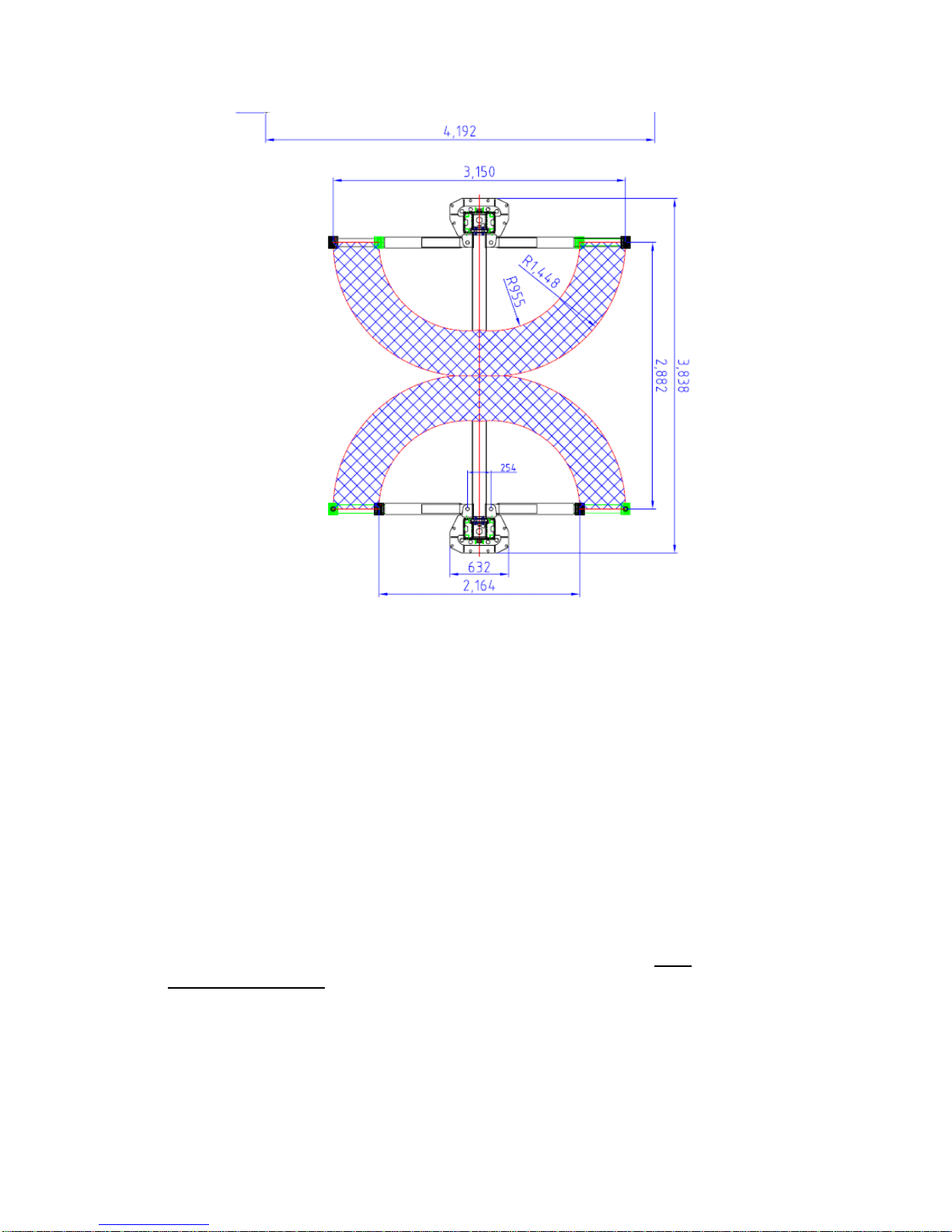
•Use architects' plans when available. See Floor Layout on Page 6 for typical layout
of the12000# inverted cylinder model.
•Two Post Lifts require a minimum ceiling height of 3” higher than the overall height
of the lift being installed. For the TP12KC-D this will be 168” (14').
•The Steel Reinforced Concrete floor must be level, have a minimum thickness of 4
inches, and retain a commercial rating of 3500 psi. The concrete must be cured for a
minimum of 28 days.
•Before making a Final Decision, consider the amount of workday traffic flowing in
and around the location you have chosen. Also consider the amount of room out front
of the lift for a workbench or diagnostic equipment. There may also be some future
building plans to consider. Are you satisfied with your selection?

4
1. There are numerous blends and mixes and additives these days for concrete. All of
these work well when used in the proper application. However, years of experience have
shown that nothing beats a properly cured, steel reinforced concrete slab for this
application. Another thing to watch is additives that claim to harden the concrete faster or
reduce the cure time. Again, these things have their place, but not in this application! A
steel rod or mesh reinforced slab cured 28-30 days with the slab kept properly hydrated
gives the best results.
2. Checking bolts for tightness to some people means that once a week they grab a
wrench and go around yanking a quarter of a turn on every nut and bolt they see. This is,
of course, not the proper way of handling any bolt, especially the stress anchor used to
anchor your lift. When the anchors are installed, they must be torqued with a torque
wrench to 150 foot-pounds initially. After a period of time, they will loosen up some.
This is normal. When checking the anchors just put a wrench on them and “feel of them”
or apply a small amount of torque to the bolt. If it is tight, it is good to go. If it is loose,
get a torque wrench and tighten it to 60-90 foot-pounds.
3. The lift is not designed for an outdoor installation because of the possible damage and
degradation to the hydraulics and the electrical components caused by direct exposure to
the elements. If the unit is installed in a building or outbuilding with a floor that is
anything other than the recommended concrete floor, a pad can be poured. The size and
construction of the pad can vary depending on the soil conditions and the local weather
conditions. It is recommended that each of these situations be handled separately by a
local engineer.
4. Never place a lift in a pit or depression in a garage area or any environment where
gasoline is around. Gasoline fumes tend to gather at the floor and low areas, so the lift
must be mounted on the main floor of the building and not in the basement or a pit.
5. Always remember that your lift is rated at 12000 pounds. This means that the lift will
safely and reliably lift a load of 12000 pounds as long as that load is evenly distributed on
all four arms. If the load is offset or unevenly distributed, then one post can actually be
operating at a load greater than 12000# and the lift can be overloaded with less than the
rated load. So the lift load rating is 12000 pounds or 3000 pounds per arm.
Positioning the Post (Columns)
Important General Information

5
Carefully examine the packed unit for damage before unpacking. Any claims for damage
should be filed with the freight carrier at delivery. Unbolt the package being careful to
save the bolts and use them to reinstall the top caps after unpacking the lift. Place posts in
bay using dimensions shown in Floor Layout (Figure 1). The bases must be square with
the layout lines as shown. It is recommended that the extensions be mounted to the posts
before standing them up. You will need a considerable amount of help standing up these
posts.
Drilling and Anchoring
A. Drill 3/4” x 5-1/2” (minimum depth) holes in the concrete floor using the holes in the
base plates as guides. Drill the holes perpendicular to the surface, being sure not to
enlarge them by allowing the drill to wobble. Do not ream-out the holes. (See Anchoring
Instructions, Figure 2). Be careful when drilling the holes, the posts can tip over.
B. Blow all of the dust and debris from the holes, then clean around the openings with
a wire brush. A clean hole will improve the prospect of solid anchoring.
c. It is recommended that the lift to be located 10’ – 12’ from the nearest obstruction
in front of the lift and 2’ – 3’ from the nearest obstruction on the sides of the lift.
2. To install Anchor:
A. Assemble the washer and nut onto the anchor bolt with nut just below impact section
of bolt.
B. With a hammer, carefully tap the anchor bolt into the concrete until the washer is
resting on the base of the column. DO NOT DAMAGE THE NUT OR THREADS!
C. Before tightening the nuts, level and plumb the columns, using the shims provided.
Note: If more than 1/2” of shims is required to level the post, Do Not Use the
Anchors supplied with this lift. It will be necessary to purchase longer anchors
for your application. The brand of anchor recommended is the Hilti Kwik-Bolt.
D. When columns are level and plumb, tighten the nuts with a Torque Wrench to 150 ft-
lb. If anchors do not tighten to 150 ft-lbs in existing floor, replace concrete under
each post with a 6’ x 6’ x 10” thick pad keyed into and flush with the existing floor.
Concrete must be 3500 PSI minimum.

6
Attaching The Overhead Beam and Shut-Off Bar
1. The overhead beam is attached to the extensions at the ends with eight nuts and bolts.
See picture.
2. The cable sheaves must assembled onto the shafts with the spacers supplied as shown
in the picture prior to attaching the overhead channel.
3.To Install the Shut-Off Bar
Attach the shutoff bar and switch housing to the underside of the overhead beam. Attach
single bolt and bar first, then install switch housing.
4. Run electrical cord into the beam and back out of the column using provided bulk
head fittings.
NOTE: NEVER USE AN IMPACT WRENCH TO TIGHTEN ANCHOR BOLTS!
7
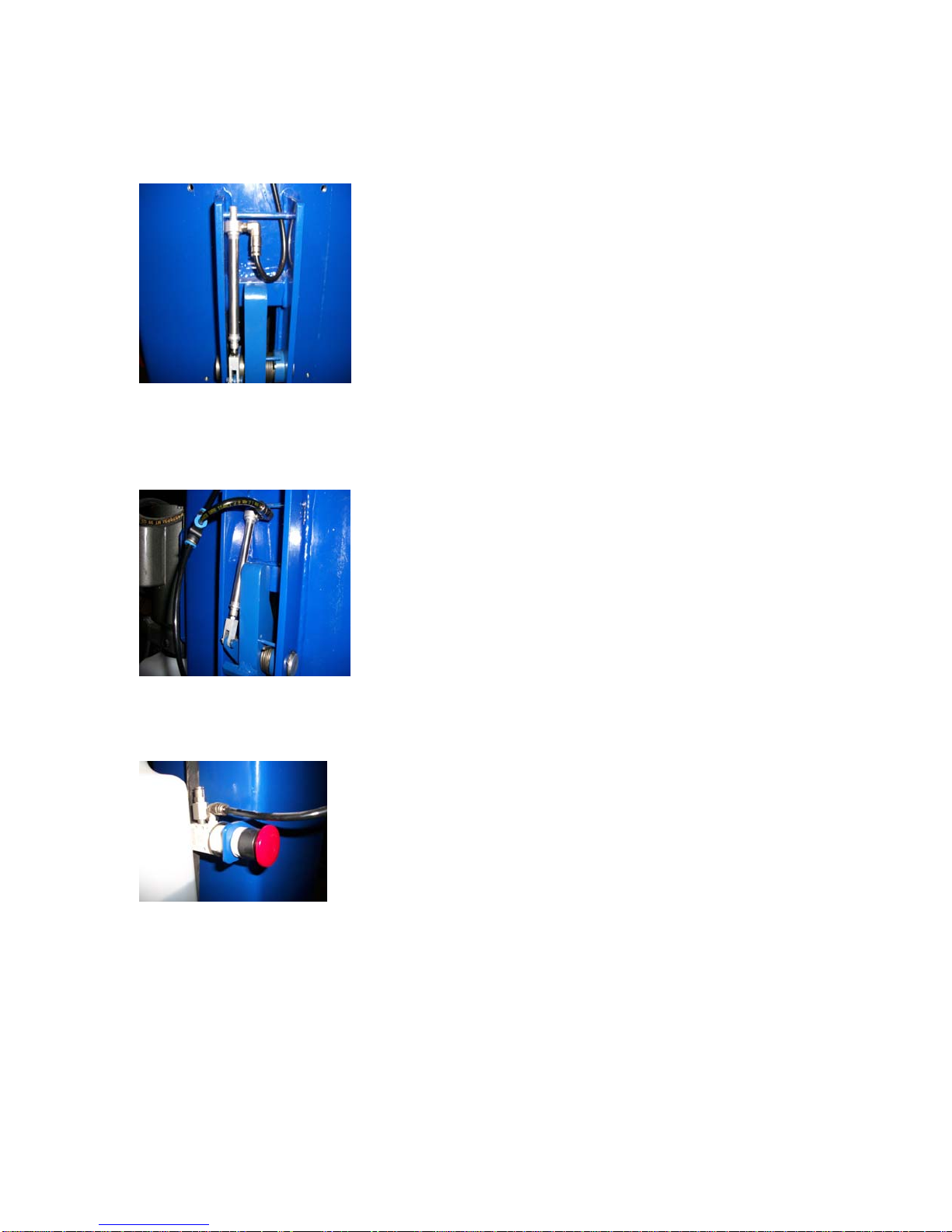
Attaching the Air Actuator
1. Locate offside air cylinder and insert 6mm hose into PTC fitting.
2.Run air hose up and over top of column, running through top side of overhead beam
and down to main side lock assembly.
3.Connect air hose to provided PTC 3-way fitting, cut to size a piece of air hose and run
to main side air cylinder PTC fitting. Remaining hose will be connected from 3-way
fitting to palm actuated air release button valve.
4.Attach palm valve to steel bracket on side of column.
5.Connect shop air to palm valve. We recommend using leftover hose and NPT fitting
(not included).
Installing the Equalizer Cables
A. Manually lift both carriages to about waist height. Be sure they are the same height
and on the same latch location on the carriage.
8
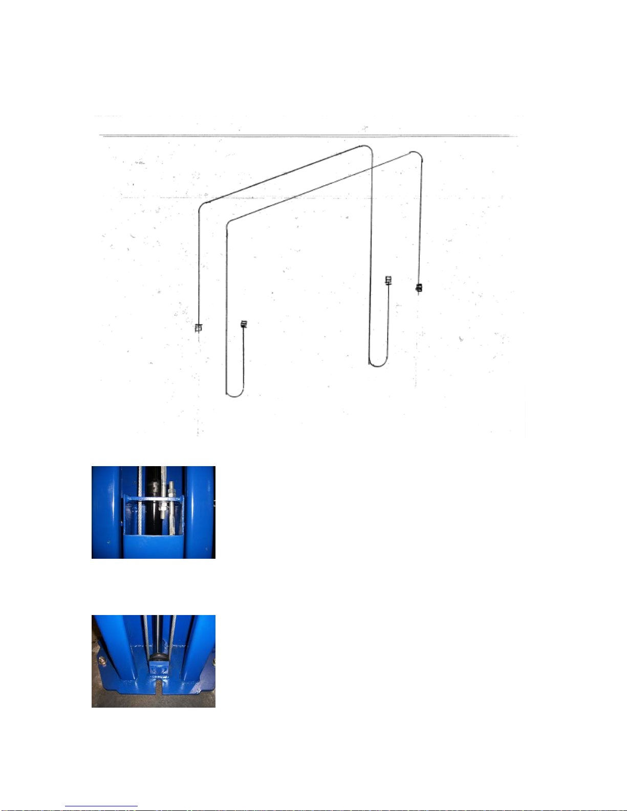
B. Install the Equalizer Cables using the Routing for the lift as shown in the picture. The
cables should be taught, but no too tight. Be certain to tighten the jam nuts.
Cables are routed identically the same on both columns. Cable on right is routed down
and around the sheave then up and over the overhead beam. Then routed down to the top
of the carriage.
Be sure cables are seated securely on the sheaves.

9
Power Unit Placement and Connection of the Hydraulic Hoses
1. Remove the power unit from the box and locate the mounting hardware. For easy
mounting, place two bolts through the middle slots on the power unit mounting plate and
start the nuts on them. Then lift the unit up and slide the unit into position while guiding
the bolts into the slots on the bracket from the top. Install the other two bolts and tighten
securely.
2. Install longest hose first. One end has 90 degree fitting that hooks to bottom of the
offside cylinder and then route hose through the leg gusset.
DO NOT OVER TIGHTEN FITTINGS!!.
3. Route the hose up the column installing the hose clamps as you go. Then follow
across the outside of the overhead beam (installing hose clamps as you go). Down the
main side column towards your power unit.
4. Run hose through the top of your power unit bracket until the end of your hose comes
through the bottom of the bracket.
5. Install power unit elbow fitting into the port that has the red plastic cap located on the
left side of your power unit. Connect shortest hydraulic hose to the elbow fitting.
Connect the T fitting to the shortest hose and then connect overhead hose to the T
fitting.
6. Connect medium length hose with 90 degree fitting to main side cylinder and thread
through leg gussets. Run the hose up to the T fitting and tighten. See pictures –

10
Attaching the Swing Arms and Arm Restraints
1. Locate the arms, arm pivot pins, and hardware. Place the arm clevis end into the clevis
on the carriage. Place thrust washer on bottom side of carriage clevis.
2. Slide the pivot pins through the arms and carriage until it bottoms out.
3. Check the operation of the arm restraints. Make sure they engage and disengage
properly.
NOTE: DO NOT OVER-TIGHTEN THE HYDRAULIC HOSE
CONNECTIONS!

11
Electrical Connection
Filling the Hydraulic Fluid Tank
Remove the vent-cap from the top of the Hydraulic Fluid Tank attached to the Power
Unit. Using a funnel, carefully pour in the Hydraulic Fluid (approximately 12 quarts)
until fluid gets near the top of the tank. Replace the vent-cap.
***********************************************
We Recommend Using One of the Following Fluids:
Dextron III Non-Detergent
AW #32 Hydraulic Oil
***********************************************
NOTE: WE STRONGLY RECOMMEND THAT YOU USE A
LICENSED, PROFESSIONAL ELECTRICIAN TO INSTALL
THE POWER TO YOUR TWO POST LIFT!

12
Bleeding the System
1. Actuate the power unit and hold the button until both carriages lift off the locks.
2. Carefully loosen the bleeding screw at top end of the cylinder and allow the trapped
air to escape. CAUTION! The air in the cylinders is under pressure. Protect your
eyes and cover the end of the cylinder with a rag because oil may spray out of the
cylinder.
3. Repeat the process for the other cylinder.
CAUTION: DO NOT OVER TIGHTEN THE BLEED PLUG
Adjusting the Equalizer Cables to Synchronize Carriages
Raise and lower the lift several times while listening to the clicking of the safety locks
in each column. If the safety locks are not clicking in unison (at the same time),
determine which carriage is running behind, and tighten (just a few turns) the
adjustment bolt on the opposite side. When the cables are properly adjusted, they
should feel fairly tight.
Final Assembly
1. Using the adhesive cable anchors and cable ties, fasten the overhead switch cord and
the air lines to the posts.
2. Install lock release covers over both assemblies with provided screws.
3. Check all nuts and bolts, making sure they are tight. Check the jam nuts on the
equalizer cables for tightness.
4. Check all of the hydraulic fittings for possible leaks. Check all the fittings for
proper tightness.
5. Make sure the Carriages are synchronized.
6. Make sure post are greased.
7. Place a vehicle on the lift (see operating section for instructions below for to the safe
and proper way to lift a vehicle), raising the vehicle until it clears the floor. Lower the
lift all the way to the floor and recheck all the anchor bolts. Raise the vehicle all the
way to the top and lower all the way to the floor several times. This procedure will
ready the lift for continued operation.
OPERATION
1. Center the vehicle left and right between the posts.

13
2. Position the swivel pads under the frame of the car at the proper lifting points.
(To find the proper lifting points, consult the vehicle’s service manual or other
approved publication.)
3. Push the up button and raise the lift until the swivel pads make contact with lifting
points.
4. Check all swivel pads to make certain all adapters are making full and proper
contact. NEVER go under a vehicle unless all adapters are in secure contact with
the vehicle.
5. Raise the vehicle approximately 2 feet and check the stability by rocking the
vehicle. Make sure vehicle weight is centered. Do not raise if weight is front or
tail heavy.
6. Raise the vehicle to the desired height and lower on the carriage latches. NEVER
go under a vehicle unless the carriage latches are engaged. If any heavy parts are
to be removed, use a set of high stands for added safety.
7. Before lowering, check the area under the vehicle to be sure it is clear. Raise lift
slightly, pull the Latch Release Handle and hold, then pull down on the lowering
release arm and lower SLOWLY. Keep feet clear.
8. After lowering, rotate the swing arms back out of the way.
MAINTENANCE SCHEDULE
DAILY
1. Always keep bolts tight.
2. Check for oil leaks.
MONTHLY:
1. Re-torque the anchor bolts if necessary. (See CAUTION! below)
2. Lubricate chains/cables with spray lubricant.
3. Check all connectors, bolts and pins to insure proper mounting.
4. Make a visual inspection of all hydraulic hoses and lines for possible wear or
interference.
!


16
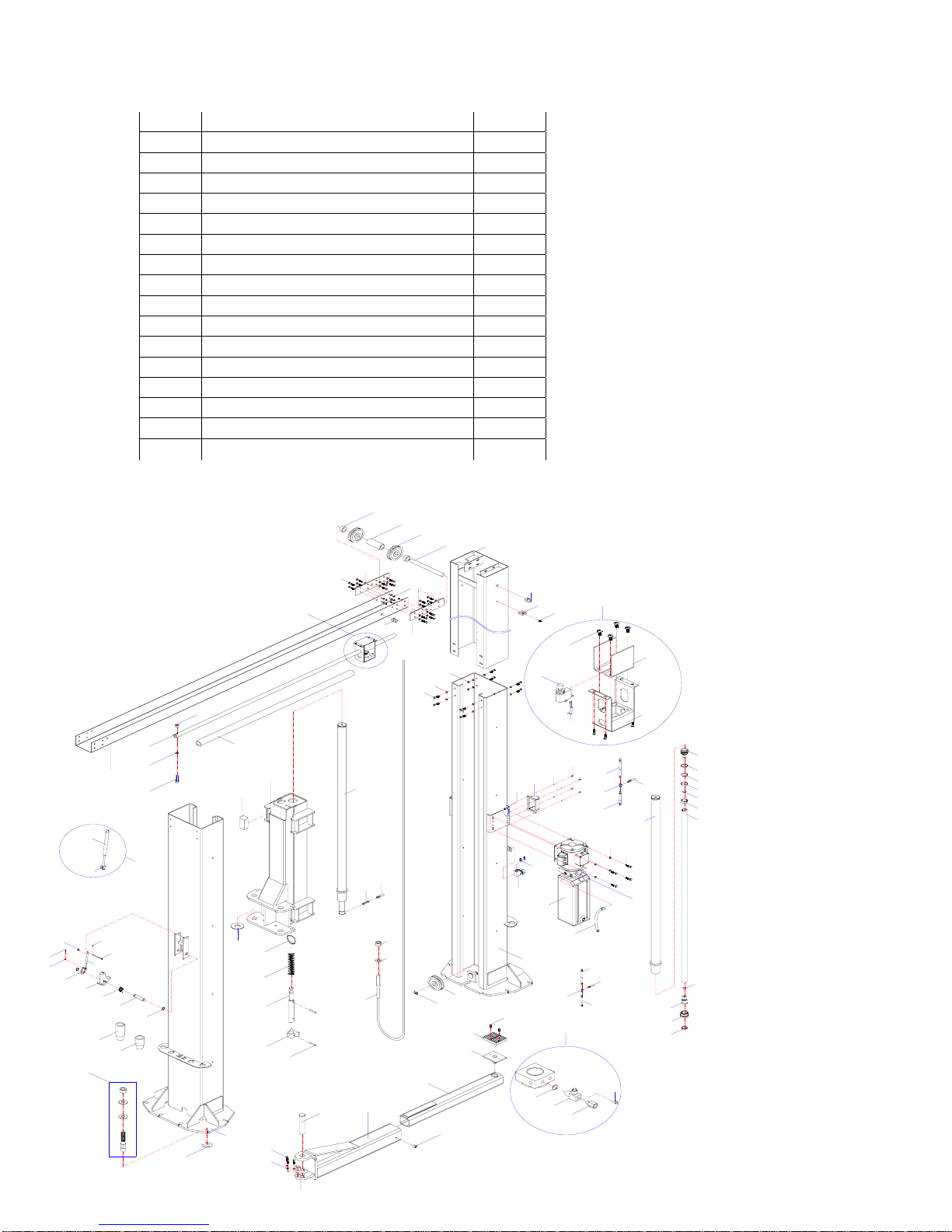
ITEM DESCRIPTION QTY
1 Column jointings 1
2 Adjust washer 12
3 Upset bolt 12
4 Spindle 4
5 Spindle 4
6 Baffle ring 6
7 Pin 2
8 Spring 2
9 Safety ass'y 2
10 Cam 2
11 Pin 2
13 Elbow fitting joint 2
14 Pin 4
15 Pin 2
16 Fitting joint 2
17 Cylinder 2
18 Cross beam parts 1
19 Bolt 5
20 Washer 9
21 Pole 1
22 Nut 5
23 Sponge bush 1
24 Rubber block 16
25 Carriage 2
26 Hydraulic cylinder 2
26-1 Cylinder barrel 2
*26-2 Dust ring 2
26-3 Guide ring 2
26-4 Fixed part for piston 2
*26-5 O-ring 4
26-6 Piston rod 2
26-7 Limit ring 2
*26-8 Guide ring 2
*26-9 O-ring 2
*26-10 Packing ring 2
63 Pin 4
64 Gear 4
65 Pin 8
66 Gear 4
67 Rack spindle 4
68 Spring 4
69 Key ring 4
70 Fitting joint 2
71 Nut 8
72 Washer 4
73 Steel cable 2
*74 O-Ring 1

17
75 T fitting joint 1
76 Fitting joint 1
77 Plug 1
28 Flat washer 104
29 Nut 48
30 Link plank 4
31 Cap 2
32 Bush 4
33 Bush 2
34 Wheel 6
35 Spindle 2
36 Vice column jointings 2
37 Hoop 16
38 Screw 16
39 Screw 16
40 Plate 1
41 Switch cover 1
42 Switch 1
43 Cable 1
44 Oil hose 1
45 Oil hose 1
46 T fitting joint 1
47 Oil hose 1
48 Flat washer 8
49 Cover 2
50 Elbow fitting joint 2
51 Switch 1
52 Power unit 1
53 Column jointings 1
54 Air hose 1
55 Air hose 1
56 Air hose 1
57 T fitting joint 1
58 Screw 12
59 Rubber washer 4
60 Salver jointing 4
61 Flex arm 4
63 Pin 4
64 Gear 4
65 Pin 8
66 Gear 4
67 Rack spindle 4
68 Spring 4
69 Key ring 4
70 Fitting joint 2
71 Nut 8
72 Washer 4
73 Steel cable 2
*74 O-Ring 1
18
75 T fitting joint 1
76 Fitting joint 1
77 Plug 1
64 Gear 4
65 Pin 8
66 Gear 4
67 Rack spindle 4
68 Spring 4
69 Key ring 4
70 Fitting joint 2
71 Nut 8
72 Washer 4
73 Steel cable 2
*74 O-Ring 1
75 T fitting joint 1
76 Fitting joint 1
78 Washer 4
A
A
2
3
4
5
6
7
8
9
10
11
1413 14
15
B
1
18 19
20
21
22
23
24 25
69
68
27 28 29
32 33
35
34
3738
39
42 40
28
27
29
39
48
49
22
51
44
45
46
47
2019
52
44
53
59
34
6
60
7047
71
72
73
61
58
62
63
27
28
64
67
66 65
58
57 56
55
54
30
17 B
26
26-1 26-6
26-7
26-5
26-8
26-9
26-10
26-11
26-5
26-4
36
31
31
50
41
43
26-3
26-2
16
C
7475 76
77
C
78
Table of contents
Other IDEAL Automobile Accessories manuals


