IDEAL TP12KC-DX User manual
Jun 2017
TP12KC-DX
Two Post Clear Floor
Automotive Lift
12,000 lb. Capacity
(3,000 lbs. Max Capacity per Arm)
Installation & Operation Manual
IMPORTANT!!
READ MANUAL THOROUGHLY BEFORE INSTALLING, OPERATING,
SERVICING OR MAINTAINING LIFT

2
TP12KC-DX
Jun 2017
INDEX
PREFACE--------------------------------------------------------------------------- PAGE 2
PRODUCT IDENTIFICATION--------------------------------------------------PAGE 2
SAVE THESE INSTRUCTIONS---------------------------------------------- PAGE 2
OWNER / EMPLOYER OBLIGATIONS------------------------------------- PAGE 3
IMPORTANT SAFETY INSTRUCTIONS----------------------------------- PAGE 4
LOCATION------------------------------------------------------------------------- PAGE 5
SAFETY DECALS---------------------------------------------------------------- PAGE 6
IMPORTANT INFORMATION------------------------------------------------- PAGE 7
PRODUCT INFORMATION---------------------------------------------------- PAGE 8
INSTALLATION------------------------------------------------------------------- PAGE 10
OPERATION----------------------------------------------------------------------- PAGE 22
INSPECTION & MAINTENANCE INSTRUCTIONS --------------------- PAGE 25
EXPLODED VIEWS & PARTS LISTS -------------------------------------- PAGE 28
TROUBLESHOOTING GUIDE------------------------------------------------ PAGE 32
WARRANTY POLICY------------------------------------------------------------ PAGE 33
PREFACE
Prior to the operation of your lift make sure that you have read the instructions thoroughly. These
instructions are found in this manual. Please note that your warranty can be voided if you do not read
the manual and understand its content.
If you have any questions, concerning operation, safety or application of your lift, please consult your
distributor.
PRODUCT IDENTIFICATION
IMPORTANT
SAVE THESE INSTRUCTIONS

3
TP12KC-DX
Jun 2017
OWNER / EMPLOYER OBLIGATIONS
1. The Owner/Employer shall ensure that lift operators are qualified and that they are trained in the
safe use and operation of the lift using the manufacturer’s operating instructions; ALI/SM10-1, ALI
Lifting it Right safety manual; ALI/ST-10 ALI Safety Tips card; ANSI/ALI ALOIM-2008 (R2013),
American National Standard for Automotive Lifts - Safety Requirements for Operation,
Inspection and Maintenance; ALI/WL101 Series, ALI Uniform Warning Label
Decals/Placards; and in the case of frame engaging lifts, ALI/LP-GUIDE, Vehicle Lifting
Points/Quick Reference Guide for Frame Engaging Lifts.
2. The Owner/Employer shall establish procedures to periodically inspect the lift in accordance with
the lift manufacturer’s instructions or ANSI/ALI ALOIM-2008 (R2013), American National
Standard for Automotive Lifts - Safety Requirements for Operation, Inspection and
Maintenance; and the Employer shall ensure that the lift inspectors are qualified and that they are
adequately trained in the inspection of the lift.
3. The Owner/Employer shall establish procedures to periodically maintain the lift in accordance with
the lift manufacturer’s instructions or ANSI/ALI ALOIM-2008 (R2013), American National
Standard for Automotive Lifts - Safety Requirements for Operation, Inspection and
Maintenance; and the Employer shall ensure that the lift maintenance personnel are qualified and
that they are adequately trained in the maintenance of the lift.
4. The Owner/Employer shall maintain the periodic inspection and maintenance records
recommended by the lift manufacturer’s instructions or ANSI/ALI ALOIM-2008 R2013), American
National Standard for Automotive Lifts - Safety Requirements for Operation, Inspection and
Maintenance.
5. The Owner/Employer shall display the lift manufacturer’s operating instructions; ALI/SM 10-1, ALI
Lifting it Right safety manual; ALI/ST-10 ALI Safety Tips card; ANSI/ALI ALOIM-2008 (R2013),
American National Standard for Automotive Lifts - Safety Requirements for Operation,
Inspection and Maintenance; ALI/WL Series, ALI Uniform Warning Label Decals/Placards; and
in the case of frame engaging lifts, ALI/LP- GUIDE, Vehicle Lifting Points/Quick Reference
Guide for Frame Engaging Lifts in a conspicuous location in the lift area convenient to the
operator.
6. The Owner/Operator shall provide necessary lockout/tag out means for energy sources per ANSI
Z244.1-1982 (R1993), Safety Requirements for the Lockout/Tag out of Energy Sources,
before beginning any lift repairs and maintenance.

4
TP12KC-DX
Jun 2017
7. The Owner/Employer shall not modify the lift in any manner without the prior written consent of the
manufacturer.
IMPORTANT SAFETY INSTRUCTIONS
When using this lift, basic safety precautions should always be followed,
including the following:
1. Do not raise a vehicle on the lift until the installation is completed as described in this manual.
2. Always position the arms and adapters properly out of the way before pulling the vehicle into,
or out of the bay. Failure to do so could damage the vehicle and/or the lift.
3. Do not overload the lift. The capacity of the lift is shown on cover of this document and on the
lift’s serial number tag.
4. Note that the removal or installation of some vehicle parts may cause a critical load shift in the
center of gravity and may cause the vehicle to become unstable. Refer to the vehicle
manufacturer’s service manual for recommended procedures.
5. Positioning the vehicle is very important. Only trained technicians should position the vehicle
on the lift. Never allow anyone to stand in the path of the vehicle as it is being positioned and
never raise vehicle with passengers inside.
6. Position the arms to the vehicle manufacturer’s recommended pickup points. Raise the lift until
contact is made with the vehicle. Make sure that the arms have properly engaged the vehicle
before raising the lift to a working height.
7. Keep everyone clear of the lift when the lift is moving, the locking mechanism is disengaged, or
the vehicle is in danger of falling.
8. Unauthorized personnel should never be in the shop area when the lift is in use.
9. Inspect the lift daily. The lift should never be operated if it has damaged components, or is
malfunctioning. Only qualified technicians should service the lift.
10.Service and maintain the unit only with authorized or approved replacement parts.
11.Keep the area around the lift clear of obstacles.
12.Never override the self-returning lift controls.
13.Use safety stands when removing or installing heavy vehicle components.
14.Avoid excessive rocking of the vehicle when it is on the lift.

5
TP12KC-DX
Jun 2017
15.To reduce the risk of personal injury, keep hair, loose clothing, fingers, and all body parts away
from moving parts.
16.To reduce the risk of electric shock, do not use the lift when wet, do not expose the lift to rain.
17.To reduce the risk of fire, do not operate equipment in the vicinity of open containers of
flammable liquids (gasoline).
18.Use the lift only as described in this manual, use only manufacturer’s recommended
attachments.
19.Unusual vehicles, such as limousines, RV’s, and long wheelbase vehicles, may not be suitable
for lifting on this equipment. If necessary, consult with the manufacturer or the manufacturer’s
representative.
20.The troubleshooting and maintenance procedures described in this manual can be done by the
lift’s owner/employer. Any other procedure should only be performed by trained lift service
personnel. These restricted procedures include, but are not limited to, the following: cylinder
replacement, carriage and safety latch replacement, leg replacement, over-head structure
replacement.
21.Anyone who will be in the vicinity of the lift when it is in use should familiarize themselves with
following Caution, Warning, and Safety related decals supplied with this lift, and replace them if
they are illegible or missing.
WARNING!! Failure by purchaser to provide the recommended mounting surface could result
in unsatisfactory lift performance, property damage, or personal injury.
For additional safety instructions regarding lifting, lift types, warning labels, preparing to lift, vehicle
spotting, vehicle lifting, maintaining load stability, emergency procedures, vehicle lowering, lift
limitations, lift maintenance, good shop practices, installation, operator training and owner/employer
responsibilities, please refer to “Lifting It Right” (ALI/SM) and “Safety Tips” (ALI/ST) and vehicle
lift points for service garage lifting SAE J2184.
For additional instruction on general requirements for lift operation, please refer to “Automotive Lift-
Safety Requirements for Operation, Inspection and Maintenance” (ANSI/ALI ALOIM).
Installation shall be performed in accordance with ANSO/ALI ALIS, Safety Requirements for
Installation and Service of Automotive Lifts.
LOCATION
This lift has been evaluated for INDOOR USE ONLY with an operating ambient temperature range of
5 - 40°C (41-104°F)
ATTENTION! This lift is intended for indoor installation only. It is prohibited to install this
product outdoors. Operating environment temperature range should be 41 – 104 °F (5 – 40 °C).
Failure to adhere will result in decertification, loss of warranty, and possible damage to
the equipment.
6
TP12KC-DX
Jun 2017
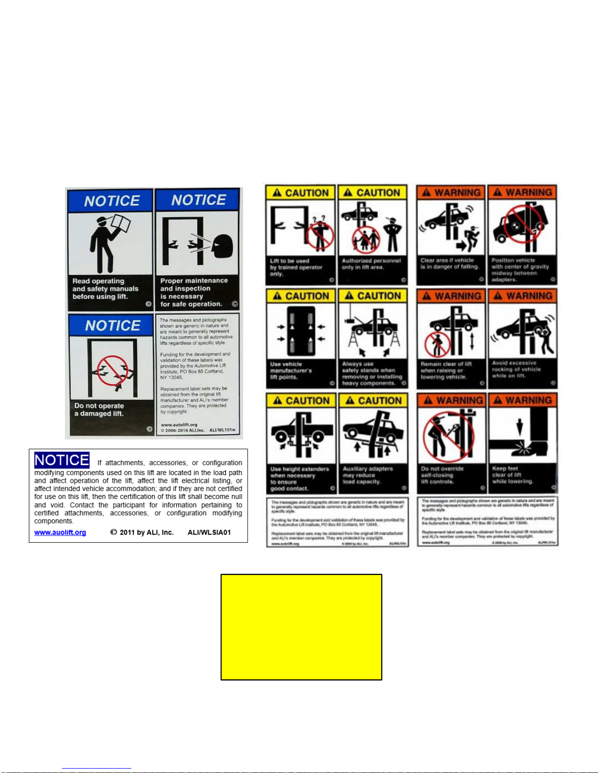
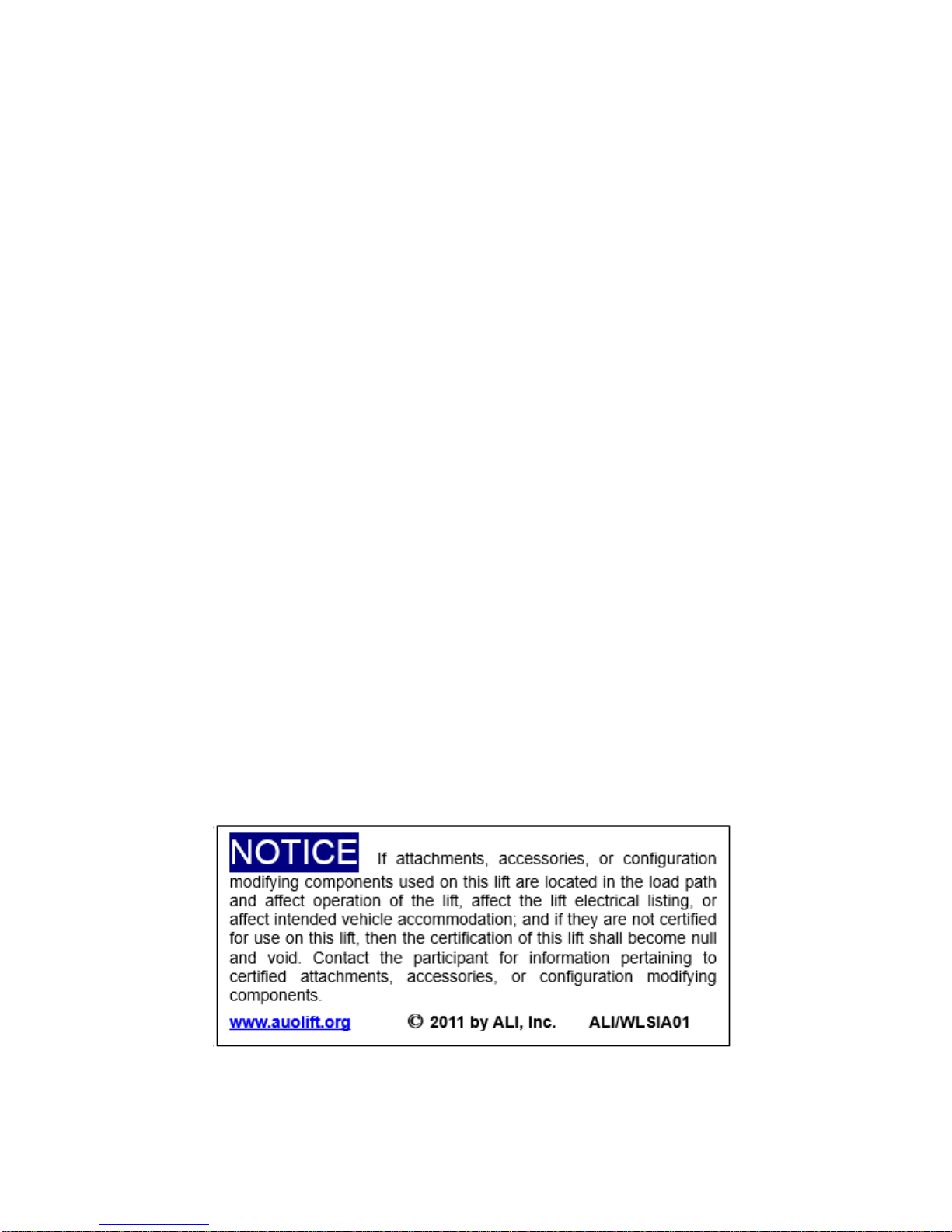
SAFETY DECALS
These Decals Must Be Applied to Lift.
NOTE: SOME IMAGES IN THIS MANUAL ARE GENERIC AND MAY NOT RESEMBLE THE LIFT
YOU HAVE PURCHASED.
REFERENCE: AUTOMOTIVE LIFT INSTITUTE, Inc.
CAUTION
RELEASE ALL LATCHES
BEFORE LOWERING LIFT
MAXIMUM CAPACITY
12,000 LBS.
7
TP12KC-DX
Jun 2017
IMPORTANT INFORMATION
1. Read this manual thoroughly before installing, operating, or maintaining this lift.
2. This lift is designed for indoor use only, and should not be installed in a pit or depression.
3. The floor on which the lift is to be installed must be 4-1/4” minimum thickness concrete,
with a minimum compressive strength of 3,500 psi.
4. The lift has specific electrical requirements as described in the Installation Instructions
section of this manual.
5. This lift has a minimum ceiling height requirement as described in the Installation
Instructions section of this manual.
6. It is recommended that the lift to be located 10’ – 12’ from the nearest obstruction in
front of the lift and 2’ – 3’ from the nearest obstruction on each side of the lift.
7. Failure by the owner to provide the recommended shelter, mounting surface, electrical
supply, and ceiling height could result in unsatisfactory lift performance, property damage, or
personal injury.
8. The operation of the lift is permitted by authorized person only.
9. Lift buyers are responsible for any special regional structural and/or seismic anchoring
requirements specified by any other agencies and/or codes such as the Uniform Building
Code (UBC) and/or International Building Code (IBC). When required, it is recommended to
contact a qualitied engineer to address the specific UBC and/or IBC code requirements.

8
TP12KC-DX
Jun 2017
1. PRODUCT INFORMATION
1.1 Product Description
The TP12KC-DX 2-post hydraulic lift is a surface mounted, frame contact lift incorporating the latest safety
technologies. Designed and manufactured for a lifting capacity of 12,000 lbs. (Max 3,500 lbs. per Lifting Arm)
and is fully capable for lifting vehicles, vans, light & heavy trucks by safely holding them in an elevated position.
The TP12KC-DX incorporates symmetric swing arms for symmetrical lifting configuration.
The TP12KC-DX 2-post hydraulic lift consists of a
fixed structural unit (Crossbeam, Columns &
Uprights), the mobile units (Carriages and Lift
Arms), and the Hydraulic Power System and
pneumatic Safety Release devices.
A. Crossbeam
B. Column
C. Carriage
D. Lifting Arm
E. Motor Pump
F. Overhead Safety Shut-Off Bar
G. Single Point Safety-Latch Release -
(pneumatic operation)
H. Upright (column extension)
1.2 Technical Data
Capacity 12,000 lbs. (Max 3,000 lbs. per Arm)
Height Overall
165”
Width Overall w/ Power Unit
151”
Max Lifting Height
72”
Max Lifting Height w/ Tallest Adaptor 77”
Width Between Columns 122”
Min Pad Height 5”
Drive Thru Clearance 109”
Swing Arm Reach – Min / Max
37-5/8” – 57”
Electrical Power
220V, 20 Amp, 1 Phase
Pneumatic Power 80 – 100 psi
Max Operating Pressure 3,050 PSI

9
TP12KC-DX
Jun 2017
Figs. 1 & 2 Elevation & Floor Layout

10
TP12KC-DX
Jun 2017
2. INSTALLATION
2.1 Site Selection
The hydraulic lift is designed only for indoor use. Application in a room with explosion hazard is not permitted.
Setting in a wet place, a car wash center for instance, is forbidden.
2.2 Surface Condition / Foundation & Anchoring
The 2-post hydraulic lift should be installed on level ground. The foundation must be 4-1/4” minimum thickness
concrete, with a minimum compressive strength of 3,500 psi. Failure in accomplish the foundation requirement
may cause the lift instability or personal injury. Installing on asphalt, soft clay floor or near the expansion gap is
prohibited.
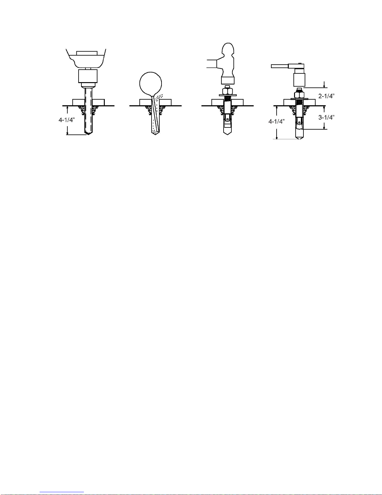
FOUNDATION and ANCHORING REQUIREMENTS
1. Concrete shall have compression strength of at least 3,500 PSI and a minimum thickness of 4-1/4” in order to
achieve a minimum anchor embedment of 3-1/4”. NOTE: When using the standard supplied 3/4” x 5-1/2” long
anchors, if the top of the anchor exceeds 2-1/4” above the floor grade, you DO NOT have enough embedment.
2. Maintain a 6” minimum distance from any slab edge or seam. Hole to hole spacing should be a minimum 4-1/2”
in any direction. Hole depth should be a minimum of 4-1/4”.
3. DO NOT install on asphalt or other similar unstable surface. Columns are supported only by anchoring to floor.
4. Using the horseshoe shims provided, shim each column base as required until each column is plumb. If one
column has to be elevated to match the plane of the other column, full size base shim plates should be used.
Torque anchors to 110 ft-lbs. Shim thickness MUST NOT exceed 1/2” when using the 5-1/2” long anchors
provided with the lift.
5. If anchors do not tighten to 110 ft-lbs. installation torque, replace the concrete under each column base with a
6’ x 6’ x 10” thick 3,500 PSI minimum concrete pad keyed under and flush with the top of existing floor. Allow
concrete to cure before installing lifts and anchors (typically 2 to 3 weeks).
ANCHORING TIPS
1. Use a concrete hammer drill with a carbide tip, solid drill bit the same diameter as the anchor, 3/4” -
(.775 to .787 inches diameter). Do not use excessively worn bits or bits which have been incorrectly sharpened.
2. Keep the drill in a perpendicular line while drilling.
3. Let the drill do the work. Do not apply excessive pressure. Lift the drill up and down occasionally to remove
residue to reduce binding.
4. Drill the hole to depth of 2” deeper than the length of anchor. NOTE: Drilling thru concrete (recommended) will
allow the anchor to be driven thru the bottom of foundation if the threads are damaged or if the lift will need to be
relocated.
5. For better holding power blow dust from the hole.
6. Place a flat washer and hex nut over threaded end of anchor, leaving the nut almost flush with the top of the
anchor bolt. Carefully tap anchor into hole. Do not damage threads. Tap anchor into the concrete until nut and
flat washer are against base plate. Do not use an impact wrench to tighten! Tighten the nut, two or three turns on
average after the concrete has cured (28-day cure). If the concrete is very hard only one or two turns may be
required.
11
TP12KC-DX
Jun 2017
FOUNDATION and ANCHORING REQUIREMENTS
Drill holes using 3/4” Clean hole. Run nut down just Tighten nut with
carbide tipped below impact section Torque wrench to
masonry drill bit per of bolt. Drive anchor 110 ft.-lbs.
ANSI standard into hole until nut and
B94.12.1977 washer contact base.
2.3 Tools & Equipment Required
•12 quarts of Non-Detergent / Non-Foaming Hydraulic Oil - SAE-10, AW 32 or equivalent
•Chalk line and 12’ Tape Measure
•Concrete hammer drill with 3/4” bit
•11/16” open end wrench
•3/4” open end wrench
•Torque wrench
•15/16” deep socket or wrench
•1-1/8” socket
•13/16” open end wrench
•Level (18” minimum length)
•Vise grips
•Tape measure
•Funnel
•Hoist or Forklift (optional)
•Two 12’ step ladders
•1/4” drive ratchet with 5/16” socket

12
TP12KC-DX
Jun 2017
2.4 Installation Procedure
1. Read this manual thoroughly before Installing, Operating, or Maintaining this lift.
2. Site Evaluation and Lift Location
A. Always use an architect’s plan when provided. Before unpacking the lift entirely, determine if the
site is adequate for the lift model being installed see figures 1 & 2 for typical bay layout and ceiling
height requirements. It is recommended to have 168” (14’) minimal celling height.
B. Determine which side will be the approach side.
C. Now determine which side you prefer the power unit to be located on. The MAIN column has the
power-unit mounting bracket attached to the side
THE POWER UNIT COLUMN CAN BE LOCATED ON EITHER SIDE. IT IS HELPFUL TO TRY
AND LOCATE THE POWER SIDE ON THE DRIVER SIDE OF THE VEHICLE WHEN LOADED
ON THE LIFT, IN ORDER TO SAVE STEPS DURING OPERATION.
D. Once a location is determined, use a carpenter’s chalk line to layout a grid for the column’s
locations.
E. After the post locations are marked, use a chalk or crayon to make an outline of the posts on the
floor at each location using the post base plates as a template.
F. Double check all dimensions and make sure that the layout is perfectly square.
DO NOT USE THESE LINES TO POSITION THE COLUMNS, FOLLOW THE INSTRUCTIONS IN
THIS MANUAL.
3. Unpack the Lift
A. Remove the lifting arms, lifting pads, height adapters, hardware box, hoses, covers, power
unit box, column extensions and overhead beam from packaging.
B. Save all packing hardware, as these components may be required to complete the installation.
C. Remove the packing bolts from brackets, which hold the two columns together.
D. Remove the upper column. Do not stand the columns up now but lay the columns with their
backs on the floor.
4. Attach Uprights / Column Extensions
A. Connect column uprights / extensions to each column using M10 bolts, washers and nuts.
DUE TO HEAVY WEIGHT OF COLUMN ASSEMBLY, IT IS RECOMMEND TO USE A HOIST OR
FORKLIFT TO ASSIST IN STANDING THE COLUMNS TO AN UPRIGHT POSTION.
13
TP12KC-DX
Jun 2017
5. Columns Positioning & Main Side Column Anchoring
A. Determine which side will be the approach side.
B. Now determine which side you prefer the power unit to be located on. The MAIN column has the
power-unit mounting bracket attached to the front side.
THE DISTANCE BETWEEN COLUMN’S BACK EDGE TO WALL, SHOULD BE AT LEAST 2 TO
3 FEET FOR SAFETY.
C. Carefully stand up the Main side column (w/ power unit bracket) & Off side column, position
the columns where they are to be secured. Ensure column’s openings are facing each other.
D. Before proceeding, double check measurements and make certain that the bases of each column
are square and aligned with the chalk line.
E. Using the column base as a template, drill the anchor bolt holes for the Main side column only!
(Refer to FOUNDATION REQUIREMENTS & ANCHORING TIPS ON PAGES 10 & 11)
NOTE: DO NOT ANCHOR OFF SIDE COLUMN AT THIS TIME!
F. Install the anchor bolts, assemble washers & nuts onto the anchor bolts. Thread the nuts onto the
anchors bolts where the tops of the nuts are just above the top of the anchor bolts. Carefully tap
the anchor bolts into the concrete until the washer rests against the base plate. Ensure not to
damage threads.
G. Using a level, plumb the Main side column both side to side and front to back. Shim the leg as
necessary using the Shims provided. Tighten anchor bolts to 110 ft. lbs. as noted on page 10. Re-
check to ensure column is plumb.
NOTE: REFER TO ‘FOUNDATION & ANCHOR REQUIREMENTS’ IF MORE THAN 1/2” OF
SHIMS ARE REQUIRED.
H. Ensure Off side column is in the correct location. DO NOT DRILL HOLES FOR ANHORS at this
time.
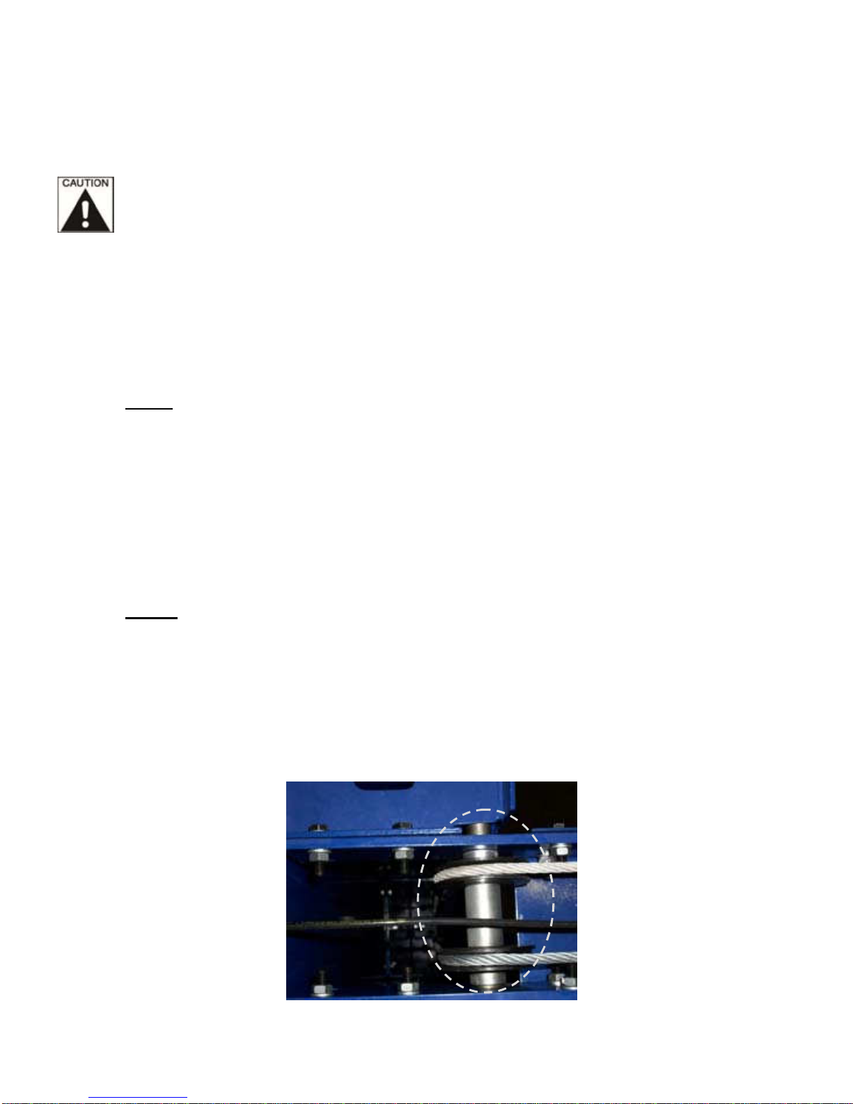
6. Install Overhead Beam & Limit Switch Bar (Figs. 3, 4 & 5)
A. Ensure the cable pulleys are assembled onto shafts with spacers prior to attaching overhead beam
to top of columns, as shown below in Fig 4.
Fig. 3

14
TP12KC-DX
Jun 2017
B. Install the overhead beam to the connection plates on each end with 8ea nuts & bolts, as shown
below in Fig.4.
Fig. 4
ENSURE TO POSITION OVERHEAD LIMIT SWITCH BOX ASSEMBLY ON SAME SIDE AS
THE MAINSIDE COLUMN WITH POWER UNIT.
C. Attach the shutoff bar and switch housing to the underside of the overhead beam. Attach single
bolt and bar first, then install switch housing.
Fig. 5
D. Run electrical cord for overhead limit switch into the hole on the underside of cross beam and back
out of the column using provided bulk head fittings.
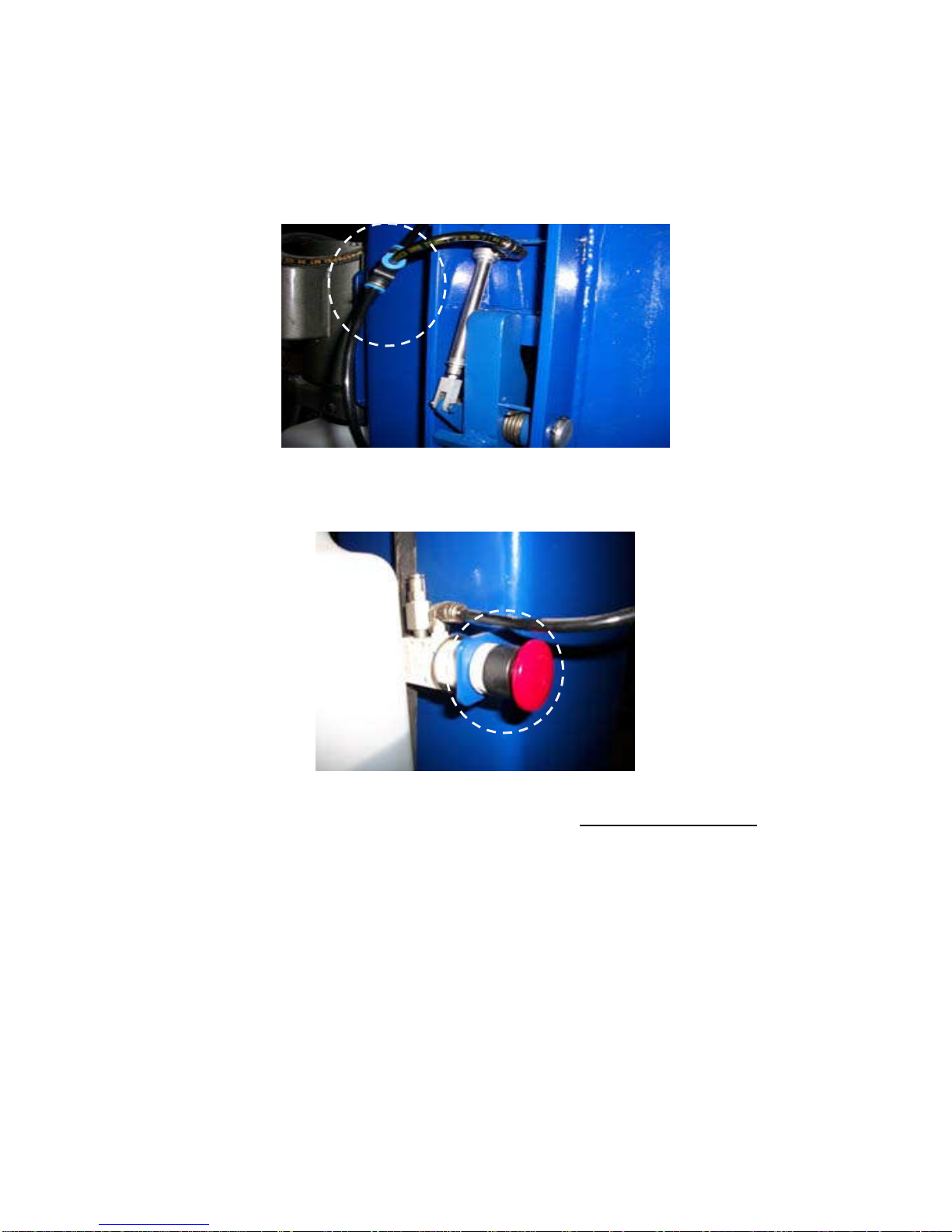
7. Install Air Actuator Cylinders for Safety Latches
A. Locate offside air cylinder and insert 6mm hose into PTC fitting, as shown below in Fig. 6.
Fig. 6
15
TP12KC-DX
Jun 2017
B. Run air hose up and over top of column, running through top side of overhead beam and down to
main side lock assembly.
C. Connect air hose to provided PTC 3-way fitting, cut to size a piece of air hose and run to main side
air cylinder PTC fitting, as shown below in Fig. 7. The remaining hose will be connected from 3-way
fitting.
Fig. 7
D. Attach palm valve to steel bracket on side of Main side column, as shown below in Fig. 8.
Fig. 8
E. Connect shop air to palm valve, using remaining air hose. NPT fitting not included.
F. Install latch covers on side of each column.
8. Anchoring Off Side Column
A. Using a level, check the alignment and plumbness of the entire structure. Plumb the off side
column both side to side and front to back.
B. The base of the column may vary from the preliminary layout, as it is more important that the
column be perpendicular to the floor and parallel to the other column.
C. Install the anchor bolts and shim the base as described in Step 5.
16
TP12KC-DX
Jun 2017
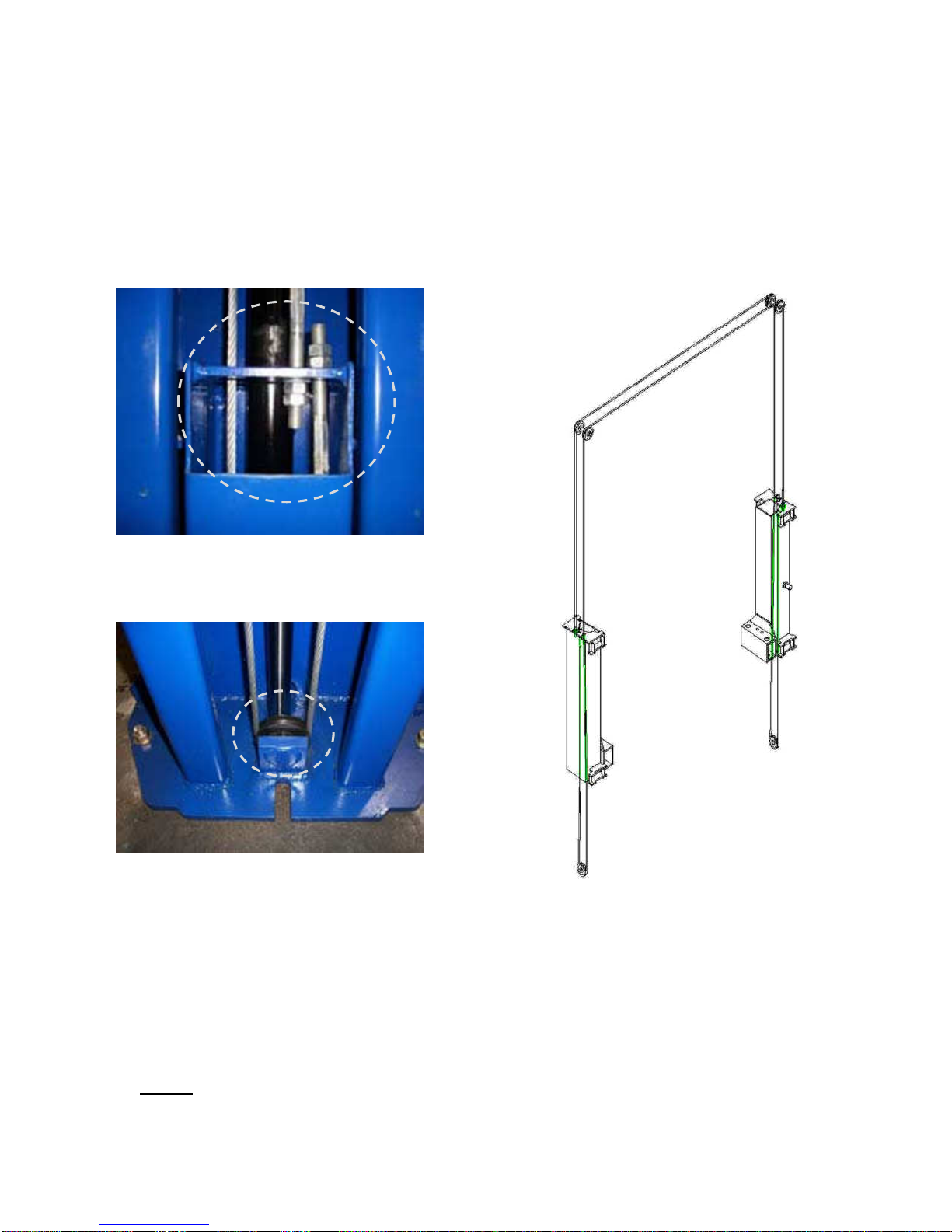
9. Equalization Cable Routing
A. The carriages should be resting on the same column latches for proper equalization. Ensure to
measure the height above the baseplate to each carriage. The measurement should be within 3/8”
of each other.
B. Using the diagrams, rout the equalization cables according to Figs. 9a, 9b & 9c from carriage to
carriage through the cable rollers. Cables are routed identically the same on both columns. Cable
on right is routed down and around the sheave then up and over the overhead beam. Then routed
down to the top of the carriage.
Fig. 9a
Fig. 9b Fig. 9c
C. Secure to carriages using Hex Nuts & Washers. Ensure that cables are not crossed together.
Take out slack but DO NOT TIGHTEN CABLES AT THIS TIME.
D. After equalizations cables are routed and connected to carriages, take out the slack in both cables
by turning down the nuts on top of each carriage top. Use vise grips to hold the cable end, but be
very careful not to damage the threads.
NOTE: CARRIAGES MUST REMAIN AT THE SAME COLUMN LOCK HEIGHT POSITION WHILE
CABLES ARE BEING TIGHTENED. FAILURE TO DO WILL CAUSE THE CARRIAGES SAFETY
LATCHES TO BE OUT OF SYNC.
17
TP12KC-DX
Jun 2017
E. Alternately tighten the cable nuts at both carriages until the cables are tightened. The correct
tension in the cables are indicated by being able to pull the cables together with approximately 15
lbs. effort at midpoint in the column. If the cables are installed correctly, both carriages will raise
together.
10. Install the Hydraulic Fittings, Hoses and Return Lines
When attaching hydraulic fittings with pipe threads to the cylinders use Teflon tape. DO NOT start
the Teflon tape closer than 1/8” from the end of the fitting. Failure to comply may cause damage
to the Hydraulic system.
When tightening connections with flared (JIC) fittings, always follow the following tightening
instructions. Failure to follow the below instructions may result in cracked fitting and/or leaks.
Use the proper size wrench.
The nut portion of the fitting is the only part that should turn during tightening. The flare
seat MUST NOT turn.
Screw the fittings together hand tight.
Rotate the nut portion of the fitting 2-1/2 hex flats.
Back the fitting off one full turn.
Again, tighten the fitting hand tight, and then rotate the nut portion of the fitting 2-1/2 hex
flats.
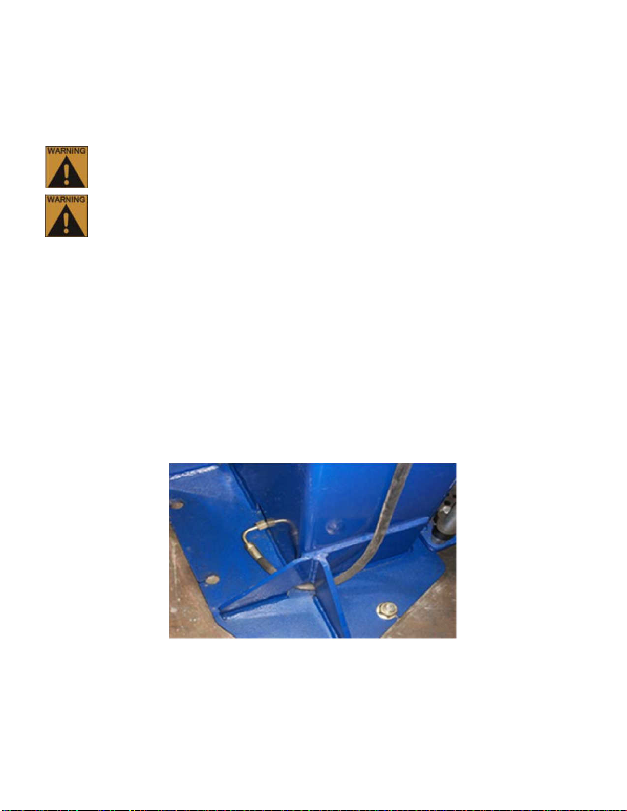
A. Fittings & Hoses Connections:
1. Install longest hose first. One end has 90 degree fitting that hooks to bottom of the
offside cylinder and then route hose through the leg gusset.(Fig.10)
2. Route the hose up the column installing the hose clamps as you go. Then follow across
the outside of the overhead beam. Down the Main side column towards the power unit
mount bracket.
Fig. 10
3. Run hose through the top of your power unit bracket until the end of your hose comes
through the bottom of the bracket, as shown in Figs. 11 &12.
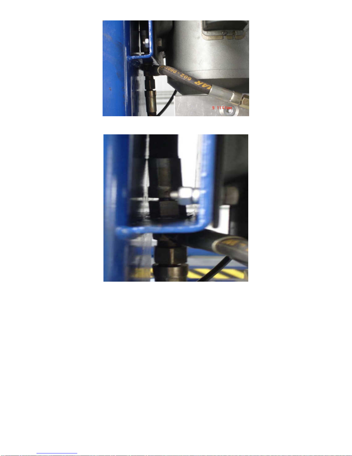
4. Connect shortest hydraulic hose to the elbow fitting. Connect the T fitting to the
shortest hose and then connect overhead hose to the T fitting, Figs. 11 & 12.
18
TP12KC-DX
Jun 2017
Fig. 11
Fig. 12
5. Then from the T-fitting inside column, connect the shortest length hose directly down to
the main inside cylinder connector.
6. Connect medium length hose with 90 degree fitting to main side cylinder and thread
through leg gussets. Run the hose up to the T fitting and tighten.
7. Install Hose Covers on sides of columns, using provided hardware. See Exploded
Views for details.
19
TP12KC-DX
Jun 2017
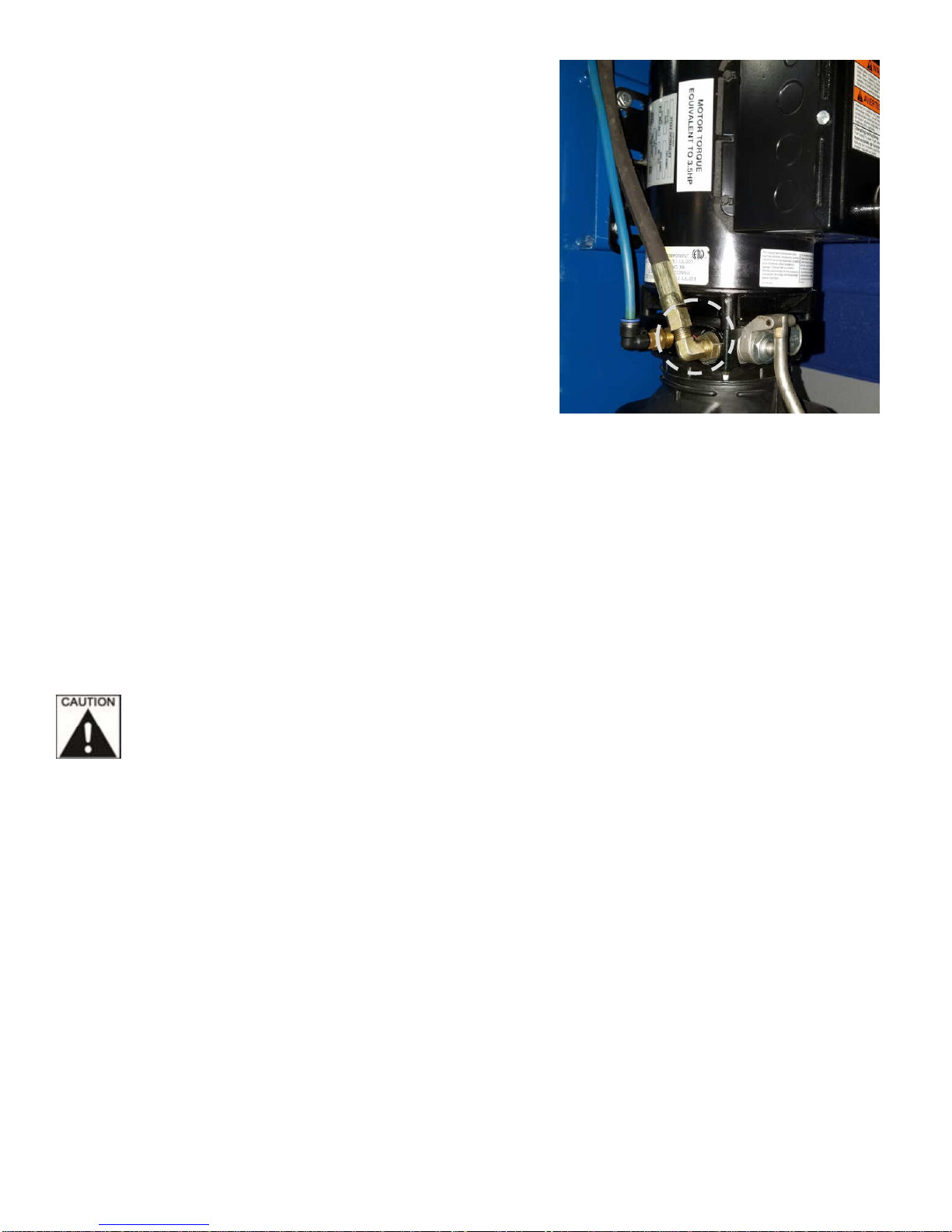
11. Mounting Power Unit
A. Mount on the motor pump using 5/16” x 1-1/4” bolts
and nylon nuts provided in the bolt box to Main side
column.
B. Connect the hydraulic hose to the 90 degree fitting,
on side of valve block, as circled in (Fig 13).
Fig. 13
12. Install Arm Restraints & Lifting Arms
A. Locate the arms, arm pivot pins, and hardware. Place the arm clevis end into the clevis on the
carriage. Place thrust washer on bottom side of carriage clevis.
B. Install the swing arms to the carriages using the pins. Secure pin to carriage with clip at bottom of
pin.
C. Check the operation of the arm restraints. Make sure they engage and disengage properly
DON’T FORCE THE GEARS, IT MAY BE NECESSARY TO PULL UP ON THE RESTRAINT ACTUATOR PIN
IN ORDER TO INSTALL THE SWING ARM PIN.
13. Filling Reservoir Tank
A. Remove the fill level screw of the power unit tank. Fill it with Dexron III ATF or hydraulic oil that meets
ISO-22, until fluid reaches the bottom of the screw hole. Replace the fill screw.
14. Lubricate the four inside corners of both columns with heavy duty grease.

20
TP12KC-DX
Jun 2017
15. Electrical Connection to Power Unit & Overhead Limit Switch
A. Have a certified electrician make the electrical connection from power supply to the power unit. Use
separate circuit for each power unit, as shown below in (Fig. 14).
B. Have a certified electrician make the electrical connection for the overhead limit switch to power unit’s
switch box, as shown in (Fig. 14).
Fig. 14
Electrical Wiring must comply with local code. Protect each circuit with time delay fuse or
circuit breaker. For 208V-230V single phase, use 20 amp fuse.
Never operate the motor in line voltage less than 208VAC as motor damage may occur.
16. Testing & Bleeding System
In this step A, there is no load on the lift.
Cycle up and down must be with interval rest of 2 mins.
A. Without a load, actuate the power unit and hold the button until both carriages lift off the locks and
carefully loosen the bleeding screw at top end of the Off side cylinder and allow the trapped air to
escape.
THE AIR IN THE CYLINDER IS UNDER PRESSURE. PROTECT YOUR EYES AND COVER
THE END OF THE CYLINDER WITH A RAG BECAUSE OIL MAY SPRAY OUT OF THE
CYLINDERS.
B. Repeat the process for the Main side cylinder.
Table of contents
Other IDEAL Automobile Accessories manuals

Popular Automobile Accessories manuals by other brands

DEFA
DEFA 412708 Fitting instructions

Draw tite
Draw tite 24941, 77328, CQT24941 installation instructions

Fiamma
Fiamma CARRY-BIKE MERCEDES VITO Installation and usage instructions

Mont Blanc
Mont Blanc MB RoofBar Flex 02 Fitting instructions

injen technology
injen technology PF2057 installation guide

Carcomm
Carcomm Quality Series quick start guide


