IDEAL ACRYLIC User manual

ACRYLIC BATHS
Installation Instructions
Please pass on to user
4950 03/13
EE74200467
4950 Baths:Layout 1 09/03/2013 04:54 Page 1

A B C Max C Min D E
Sandringham 21 1695 695 540 510 370 500
Senses 1695 695 542 500 390 450
Senses Double End 1695 745 542 500 470 470
Vue 1695 695 540 500 360 440
TECHNICAL INFORMATION
All dimensions shown in millimetres.
Dimensions shown may vary within permitted tolerances.
BEFORE YOU START
●Before commencing installation, carefully remove packaging/protective film and check for
damage. If damaged, report immediately to supplier.
●Check the packs and make sure that you have all parts listed. If not, contact the supplier.
●Ensure the water feeds and waste connection points are positioned appropriately for the
installation.
●Care should always be taken when drilling into walls and floors to avoid any sunken wires
or pipes.
●The bath should be fully protected during the installation process.
●Please note: Although these instructions are comprehensive, it is always recommended
that a technically competent installer should undertake installation.
Appropriate safety equipment/workwear should be used
The 4 black - No. 8 x 40 long countersunk crosshead
self tapping screws removed from the bath are NOT REQUIRED.
Fig. 1
4950 Baths:Layout 1 09/03/2013 04:54 Page 2

BATH COMPONENTS
Fig. 2
4950 Baths:Layout 1 09/03/2013 04:54 Page 3

Ref. F
Ref. K
Ref. E
Ref. L
Ref. G
Ref. D
Ref. J
Ref. C
Ref. B
Ref. A
Ref. H
Encapsulated
baseboard
Note: On rectangular baths,
bath legs can be installed
either way round
Use 3mm pilot holes
on all screw holes
Note: In whatever position the bath is installed
the entire bath load MUST be taken on all feet
Ref. A
Ref. B
Ref. C
Ref. J Ref. D
Ref. E
Ref. G
Ref. G
Ref. H
Ref. K
Ref. L Encapsulated
baseboard
tap bar
Note : For double ended baths.
To allow access to pipe work,
we recommend that the tap area
of the bath is installed
away from the wall.
BATH ASSEMBLY
Fig. 3
4950 Baths:Layout 1 09/03/2013 04:54 Page 4

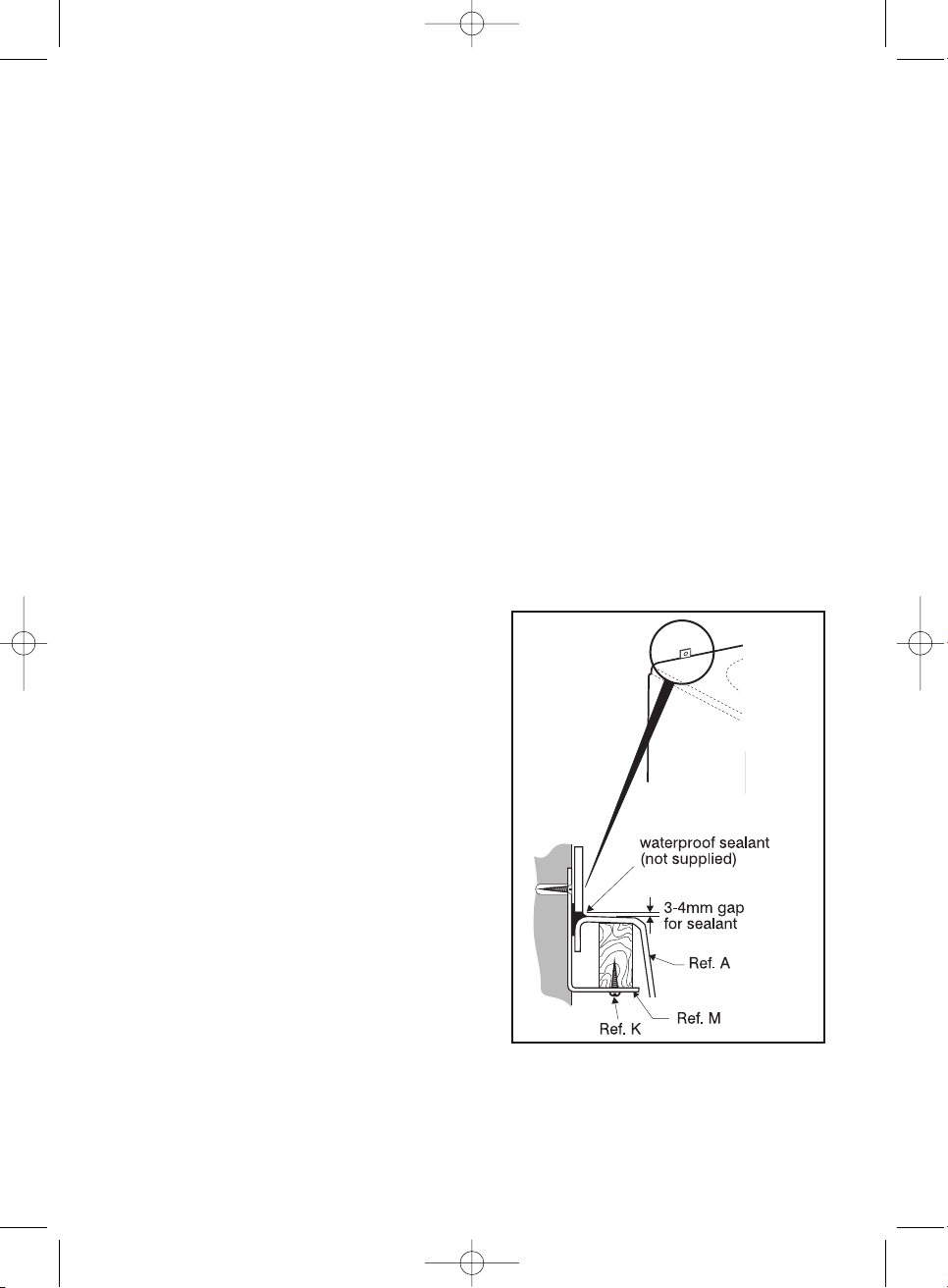
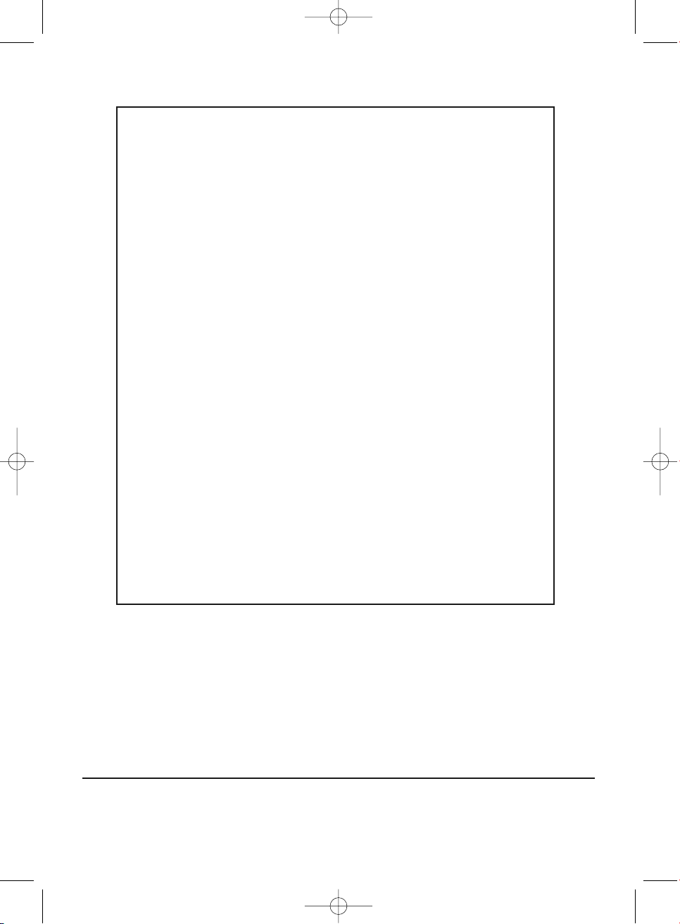
7. Fix the two wall fixing brackets, (Ref. M)
to bath frame as indicated in Fig. 4 and Fig. 1. Pilot
drill holes in frame before fixing brackets.
8. Fix bath to wall, Fig. 4.
9. Fix bath to floor, ensuring that all nuts are tight and
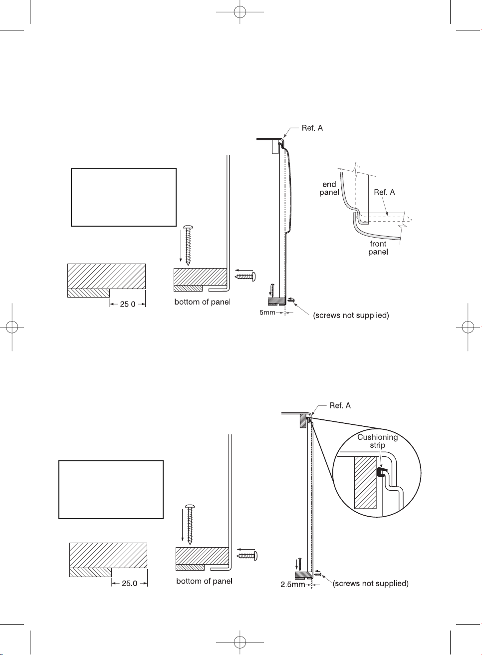
that the bath is level. Re-adjust if necessary. Trial fit
the panel(s) to verify height is correct.
Note: Untrimmed panel fitment requires the
maximum height adjustment (C max Fig. 1),
Vue- 510mm from trimmed edge of bath to floor.
Senses- 512 from trimmed edge of bath to floor.
Remember to allow for floor covering thicknesses.
10. Connect services, test for satisfactory operation of
fittings and ensure there are no leaks.
11. Tile down to the height of the bath rim leaving
a 3-4mm gap for waterproof sealant, see Fig. 4.
An extruded sealing strip can be used for the bath
to wall joint as an alternative to waterproof sealant.
Protect bath during tiling.
Fig. 4
INSTALLATION
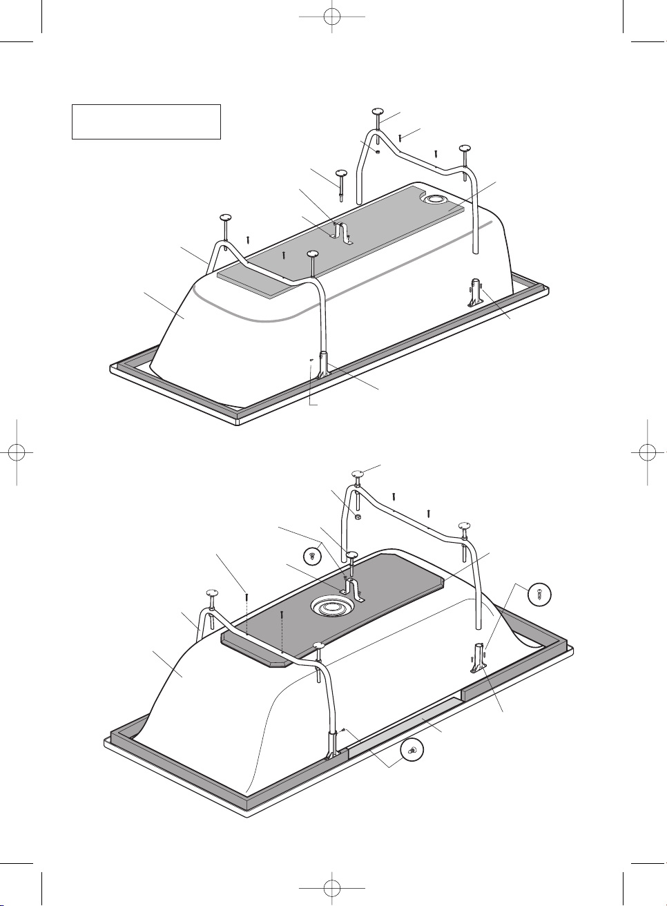
1. Lay bath face down and remove legs and bags containing feet etc. Discard the 4 black packing
screws securing the legs.
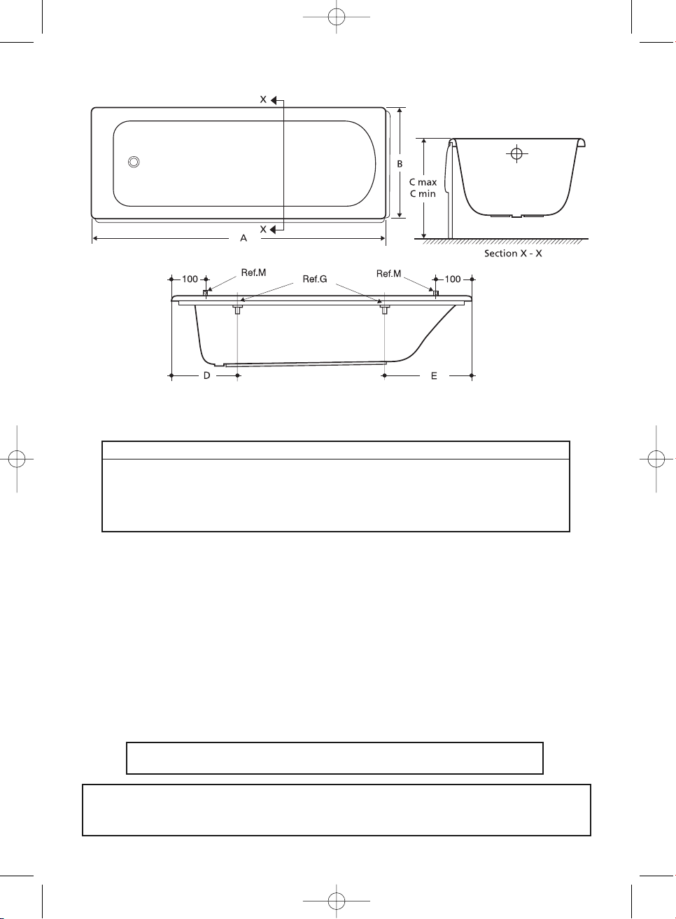
2. Locate leg adjusters, (Ref. G) on bath frame and mark positions for the fixing screws.
See Fig 1 for dimensions. Pilot drill the holes in the bath frame and fix leg adjusters to frame.
3. Locate bath legs in leg adjusters, (Ref. G) and mark positions for the fixing screws on the base
board. Pilot drill the holes in the baseboard, to a depth of 6mm maximum. Position legs in leg
adjusters and on base board and secure using screws, (Ref. L). Locate pan head self tapping
screws (Ref. H) into leg adjusters and tighten.
DO NOT OVER TIGHTEN.
4. Locate centre support bracket, (Ref. C), centrally on the base board. Mark screw hole positions,
pilot drill holes in baseboard, to a depth of 6mm maximum, and secure bracket using screws
(Ref. J).
5. Attach the feet and adjust to give floor to top of rim height of C Max. Stand the bath on its feet.
6. Fit tap and waste fittings. If the bath is to be installed with a monoblock mixer, a special hole(s)
will be required to accommodate it and will have to be cut by the installer in an appropriate
position on the rim of a no tap hole bath to suit. Full details or a template for cutting the hole(s)
is supplied with monoblock fittings. A template for cutting two tap holes in a no tap hole bath is
supplied with the bath. Cut tap holes, and fit tap fittings, waste, overflow and trap. When using a
monoblock fitting, the area directly behind the pop-up waste mechanism should be avoided.
4950 Baths:Layout 1 09/03/2013 04:54 Page 5

Suggestion
Use two separate battens
fixed together to create a
stepped panel support.
(Not supplied)
Fig. 5
Locate and fix the floor battens. Using a spirit level up against the side of the bath, mark a line on the
floor vertically down from the rim of the bath. Offset this line outwards by 5mm. This gives the approx-
imate position for the front edge of the floor batten. Fix batten(s) to floor.
Fit panel(s) (end panel first where appropriate) by pushing the top edge under the bath rim, Fig. 5.
Secure base of panels to battens using screws or other suitable fixing method, (not supplied).
12a. Panel fixation (Vue & Sandringham 21)
Locate and fix the floor battens. Using a spirit level up against the side of the bath, mark a line on the
floor vertically down from the rim of the bath. Offset this line outwards by 2.5mm. This gives the
approximate position for the front edge of the floor batten. Fix batten(s) to floor.
Fit panel(s) (end panel first where appropriate) by pushing the top edge under the bath rim, Fig. 5a.
If required, add the cushioning strip to the top of the panel for gap adjustment, (supplied).
Secure base of panels to battens using screws or other suitable fixing method, (not supplied).
12b. Panel fixation (Senses)
Fig. 5a
Suggestion
Use two separate battens
fixed together to create a
stepped panel support.
(Not supplied)
4950 Baths:Layout 1 09/03/2013 04:54 Page 6

CARE OF BATH
This bath left our works in first class condition and the following points should be
noted;
TO AVOID DISAPPOINTMENT, PLEASE REMOVE THE PROTECTIVE FILM AND
INSPECT BEFORE INSTALLATION.
Responsibility will not be accepted for the installation of faulty baths.
Care of bath - for the installer:
Keep under cover in a clean, dry, weather-proof place.
Do not drop. Protect completely during and after installation (with clean felt etc.).
When making joint to waste, overflow etc. on this product, DO NOT use linseed
oil putty or similar based sealing compounds. Ensure rubber washers supplied
with waste fittings are located correctly to give watertight seal.
Test the fittings and then do not use the bath for any other purpose.
Please leave this leaflet for the end user to read.
WARNING
1. Filling. It is advisable always to run in some cold water before turning on
the hot tap.
2. Cleaning. The bath should always be cleaned immediately after use, preferably
whilst the water is running out and the bath is still warm. The film of insoluble soap
products, body fats and grime which will otherwise harden on the side of the bath is
easily removed at this stage. In hard water districts insoluble lime salts are deposited
below the waterline and under leaking taps. If this deposit is allowed to build up, it
becomes increasingly difficult to remove and looks unsightly. Prompt cleaning is again
the answer. Hot soapy water with a cloth should be used and the bath wiped dry.
3. Cleaners of a gritty or abrasive nature should never be used. Worn washers on
dripping taps should be replaced.
4. Chemicals. Acrylic has good resistance properties to acids and alkalis but should
not be allowed to come into contact with organic solvents such as dry cleaning agents
and paint strippers.
5. Removal of scratches. In the event of slight scratches in the bath surface a mild
abrasive, similar to metal polish, can be used to polish these out.
6. Burning cigarettes should not be allowed to come into contact with the surface of
this bath or damage may ensue.
4950 Baths:Layout 1 09/03/2013 04:54 Page 7

We pursue a policy of continuing improvement in design and performance of our products. The right is,
therefore, reserved to vary specifications without notice.
CUSTOMER CARE HELPLINE
0870 1258905
FAX LINE 01482 499611
email: [email protected]
4950 03/13
Product Guarantee
25 YEARS
Idealform Acrylic baths
10 YEARS
Shower enclosures and bath screens
5 YEARS
Valves and kits, bath panels
taps and mixers
This covers products in domestic use by the consumer and not commercial or
business use.
All Ideal Standard products must be installed, used and cared for in line
with our fixing instructions, local water byelaws and current water regulations.
Access should always be left for installation, service and repair.
Any relating costs are the responsibility of the owner/installer.
Guaranteed parts will be replaced if found faulty.
This guarantee does not cover general wear and tear.
Applies to the UK and Republic of Ireland only.
Proof of purchase will be required for any warranty claim.
4950 Baths:Layout 1 09/03/2013 04:54 Page 8
Table of contents
Other IDEAL Bathtub manuals
Popular Bathtub manuals by other brands

agape
agape OTTOCENTO AVAS0967Z Assembly instructions

American Standard
American Standard Colony Oval Whirlpool and Bathing Pool... Specification sheet

DURAVIT
DURAVIT Combi L operating instructions

Kohler
Kohler Stargaze K-24019-GHW manual

Noro
Noro Single manual

American Standard
American Standard LIBERATION owner's manual

Aquatic
Aquatic SERENITY W6AIR6060 Owner's manual & installation guide

Novellini
Novellini Ship 150 installation manual

Signature Hardware
Signature Hardware HIBISCUS 948057-67-TD manual

Laufen
Laufen ALESSI 2.4597.2 manual

miseno
miseno 232068-BAT-WH installation guide

Jacuzzi
Jacuzzi essential Series Instructions for preinstallation