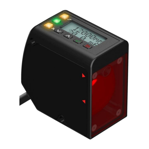
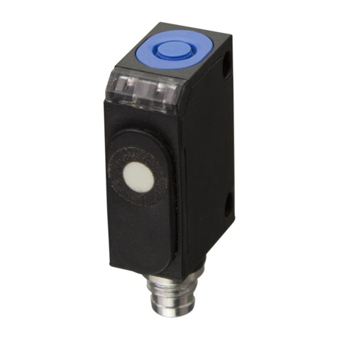
IDEC SA1J-C1NQ User manual

Sensors
SA1J : Full Color Recognition
Introducing a cost-effective solution for full color sensing applications— SA1J
full color recognition sensor. Outstanding benets of the SA1J include an extremely
high response speed (0.3ms), high resolution, and a very low cost.
Key features of the SA1J color sensor include:
• Choice of a 3-color version or a 1-color version
• Fast response (0.3ms)—perfect for sensing complex color marks
at high speed
• Three LEDs (Red, Green, and Blue) provide a long sensing life
• Easy alignment and targeting using a visible spot
• Set sensor with the touch of a button
• Highly sensitive to variations in color; can distinguish between
subtle shades of the same color
• Up to 60mm sensing distance
• IP67 rated
1-Color Version 3-Color Version
General Specifications
Power Voltage
12 to 24V DC (ripple 10% maximum)
Operating voltage: 10 to 30V DC
Current Draw
150mA maximum
Dielectric Strength
Between live and dead parts: 1,000V AC, 1 minute
Insulation Resistance
Between live and dead parts: 20M
Ω
minimum (500V DC megger)
Operating Temperature
–10 to +50˚C
(performance will be adversely affected if the sensor becomes coated with ice)
Operating Humidity 35 to 85% RH (avoid condensation)
Storage Temperature –30 to +70˚C
Vibration Resistance Damage limits: 10 to 55Hz
Single amplitude: 0.75mm
2 hours in each of 3 axes
Shock Resistance Damage limits: 500m/s
2
(approximately 50G)
5 shocks in each of 3 axes
Extraneous Light Immunity Sunlight: 10,000 lux maximum
Halogen lamp: 3,000 lux maximum
Material Housing: Aluminum
Lens: Glass
Cover: Polyarylate
Degree of Protection IP67—IEC Pub 529
Cable Cable type: ø5.4mm 5-core oiltight vinyl
cabtyre cable (0.2mm
2
) 2m long Cable type: ø5.4mm 7-core oiltight vinyl
cabtyre cable (0.2mm
2
) 2m long
Weight Approximately 250g
Dimensions (HxWxD) 1.97" x 1.18" x 3.15" (50 x 30 x 80mm)
Accessories Adjusting screwdriver
SA1J: Full Color Recognition Sensors
TREICHL-ATM Electronic Auf der Bült 10 - 12 D 41189 Mönchengladbach
Tel. 02166 958545 Fax 02166 958547

Sensors
SA1J : Full Color Recognition
Part Numbers: SA1J Sensors
1-Color Version 3-Color Version Output Spot Diameter Sensing Distance Inspection Spot
SA1J-C1N1 SA1J-C1N3 NPN ø 0.157" (ø 4mm)
ø 0.236" (ø 6mm)
ø 0.315" (ø 8mm)
1.575" (40mm)
1.969" (50mm)
2.362" (60mm) Standard
SA1J-C1P1 SA1J-C1P3 PNP
SA1J-C2N1 SA1J-C2N3 NPN ø 0.098" (ø 2.5mm)
ø 0.118" (ø 3mm)
ø 0.177" (ø 4.5mm)
0.591" (15mm)
0.787" (20mm)
0.984" (25mm) Small
SA1J-C2P1 SA1J-C2P3 PNP
1-Color Version 3-Color Version
Function Specications
Reference Color Registration
Push SET button (sensor aimed at color
target); sensor records reference color
in EEPROM memory
Set dial to A: Push SET button (sensor
aimed at color target A); sensor records
reference color A in EEPROM memory
Set dial to B: Push SET button (sensor
aimed at color target B); sensor records
reference color B in EEPROM memory
Set dial to C: Push SET button (sensor
aimed at color target C); sensor records
reference color C in EEPROM memory
Tolerance
Digital setting for 5 degrees of
inspection sensitivity Digitalsettingfor 5degreesofinspection
sensitivity (normal run mode only)
Inspection Mode
Selectable: Color component only (C) or color component plus intensity (C+I)
(depth of color)
Operation Mode
—
Selectable:
S run: Auto select, sensor determines
tolerance (no need to set tolerance)
Normal run mode: Manually select
tolerance (1–5) for each reference color
Synchronous Mode
Selectable: Internal response mode or synchronized with an external signal
Response Mode
High-speed (F): 0.3ms
Normal speed (N): 1ms
Slow speed (S): 5ms
High-speed (F): 0.8ms
Normal speed (N): 1.5ms
Slow speed (S): 6ms
Control Output
On:Detected color matches target color
NPN or PNP transistor open collector
30V DC, 100mA maximum
Residual: 1.5V maximum, short circuit
protection
Control output A on: Detected color cor-
responds to target color A*
Control output B on: Detected color cor-
responds to target color B*
Control output C on: Detected color cor-
responds to target color C*
NPN or PNP transistor open collector
30V DC, 100mA maximum
Residual: 1.5V maximum, short circuit
protection
Operation LED
On: When control output is on (yellow LED)
Off-Delay Timer
Selectable: Timer ON (T-ON) or Timer OFF (T-OFF)
Timer
OFF delay timer 40ms
SET Input
NPN:
30V DC maximum/3.6mA
(when connected to 0V)
Typical operating voltage:
(0V) +4V maximum
PNP:
30V DC maximum/3mA
(when connected to 24V)
Typical operating voltage:
(+V) –4V maximum
NPN:
30V DC maximum/3.6mA
(when connected to 0V)
Typical operating voltage:
(0V) +4V maximum
PNP:
30V DC maximum/3mA
(when connected to 24V)
Typical operating voltage:
(+V) –4V maximum
External Synchronous Input
Light Source
3 LEDs (Red, Green, Blue)
1. Each channel has its own independent short circuit protection.
2. * The target color is dened by the oper ation mode setting.
TREICHL-ATM Electronic Auf der Bült 10 - 12 D 41189 Mönchengladbach
Tel. 02166 958545 Fax 02166 958547

Sensors
SA1J : Full Color Recognition
Sorting objects by cap or lid color
Detecting objects that are the incorrect shape or color
R
G
Y
R
GG
Y
GG
Upside Down
Normal
Broken Abnormal
Normal Normal
SA1J
Detecting plastic bagging materials on a web
Detecting presence or absence of a logo on a cap or lid
1-touch programming
High-speed response rate
Detects marks—regardless
Choose between a small spot
(2.5mm) or a standard spot (8mm)
with a long distance range
of similarity of color
Cap Liner
SA1J
SA1J
IDEC IDEC
Checking packaging labels for correct position, color, and content
SA1J
Product A
Label is marked
incorrectly
Warning Warning
Warning Warning Warning Warning Wa
Label color
is incorrect Label position
is incorrect
Applications
TREICHL-ATM Electronic Auf der Bült 10 - 12 D 41189 Mönchengladbach
Tel. 02166 958545 Fax 02166 958547

Sensors
SA1J : Full Color Recognition
Operation LED: The Operation LED (Yellow) is on when the control output is
on.
Reference color set button: This button is used to memorize the reference
colorwhen the sensor isaimedat a color target.Thereference color can also
be registered using an external signal and the set input wire (SET). In either
case, the reference color existing in memory is replaced by the new refer-
ence color.
Inspection tolerance dial: Turn this dial to program one of ve different
degreesofsensitivity. Set thedial to 1 to distinguish the slightestvariation in
reference color (narrow range of tolerance). Set the dial to 5 to tolerate con-
siderable variations in the reference color (wide range of tolerance).
Inspection mode switches:
Color only (C): Color only is used to inspect on the basis of color alone,
when surrounding lights inuence intensity , or when the inspection spot
varies.
Color plus intensity (C+I): Color plus intensity is used to inspect on the
basis of color and depth of color when necessary to distinguish between
slight variations in shade.
Synchronous mode switch:
Select external or internal.
External synchronous mode (EXT):
External (EXT) is used to synchronize inspection with an external signal.
Internal synchronous mode (INT): Internal (INT) is used to perform
inspections continuously corresponding to the response mode selec-
tion. Internal response is activated when INT is selected and the refer-
ence color set button is pressed.
Same color Different color
Detected object
External
synchronous Signal
On
Off
Output Response time
t
t
1. In the gur e above, “t” represents the amount of time
the external synchronous signals should remain on in
response to the response mode.
F (fast response): 0.2ms or more
N (normal response): 0.5ms or more
S (slow response): 3ms or more
2. To prevent chattering, use a non-contact output
sensor as the external synchronous input.
Response mode switch:
Fast response mode (F): This mode is used for high-speed inspection.
Response time is 0.3ms.
Normal response mode (N): This mode is used for normal inspection.
Response time is 1ms.
Slow response mode (S): This mode is used for stable inspection.
Response time is 5ms.
Off-delay timer (T-ON/T-OFF) switch:This mode is usedto selecttheOFF-
delay timer. The timer maintains the output for 40ms.
Using External Synchronization
Using Internal Synchronization
Operation at Power ON
The light source does not go on immediately when power is turned on. The
sensor contains a circuit to initially delay the output for two seconds. To
ensure stable sensing, run a test operation for approximately 15 minutes.
Detected object
External
synchronous Signal
On
Off
Output
Same color Different color
40 ms
Detected object
On
Off
Output
Same color Different color
40 ms 40 ms
Operation (1-ColorVersion)
Control Panel
TREICHL-ATM Electronic Auf der Bült 10 - 12 D 41189 Mönchengladbach
Tel. 02166 958545 Fax 02166 958547

Sensors
SA1J : Full Color Recognition
Operation LEDs: The operation LEDs (yellow) are on when the control out-
put is on.
Reference color set button: With the reference color selector dial set to A
and with the sensor is aimed at color target A, press this button to memorize
color A. Repeat this procedure to memorize reference colors B and C.
Reference colors can also be registered by inputting an external signal using
the set input wire (SET) and the external input wire (EXT). (Refer to
Remote
Reference Color Registration
on the following page.) Existing reference col-
ors are replaced by new reference colors.
Operation mode dial/reference color selector dial:
Normal run mode (tolerance 1 to 5): Turn the dial to program one of
ve different degrees of sensitivity . Set the dial to 1 to distinguish the
slightest variation in reference color (narrow range of tolerance). Set the
dial to 5 to tolerate considerable variations in the reference color (wide
range of tolerance).
Select run mode (S RUN): This mode allows the sensor to dene the
besttolerance. (No need tosettolerance.)Low tolerance isused todistin-
guish shades of color that are similar to the reference color. High toler-
ance is used to distinguish shades of color that vary from the reference
color.The output corresponds tothereferencecolor that ismost similarto
the object detected.
Reference color selector (SET): This dial selects the reference color (A, B,
or C) for the reference color registration.
Inspection mode switches:
Color only (C): Color only is used to inspect on the basis of color alone,
when surrounding lights inuence intensity , or when the inspection spot
varies.
Color plus intensity (C+I): Color plus intensity is used to inspect on the
basis of color and depth of color when necessary to distinguish between
slight variations in shade.
Synchronous mode switch:
Select external or internal.
External synchronous mode (EXT): External (EXT) is used to synchro-
nize inspection with an external signal.
Same color Different color
Detected object
External
synchronous Signal
On
Off
Output Response time
t
t
Internal synchronous mode (INT): Internal (INT) is used to perform inspec-
tions continuously corresponding to the response mode selection. Internal
response is activated when INT is selected and the reference color set button
ispressed.
Response mode switches:
Fast response mode (F): This mode is used for high-speed inspection.
Response time is 0.8ms.
Normal response mode (N): This mode is used for normal inspection.
Response time is 1.5ms.
Slow response mode (S): This mode is used for stable inspection.
Response time is 6ms.
Off-delay timer (T-ON/T-OFF) switch: Thismodeis used toselect the OFF-
delay timer. The timer will maintain the output for 40ms.
Using External Synchronization
Using Internal Synchronization
Operation at Power ON
The light source does not go on immediately when power is turned on. The
sensor contains a circuit to initially delay the output for two seconds. To
ensure stable sensing, run a test operation for approximately 15 minutes.
1. In the previous gur e, “t” represents the amount
of time the external synchronous signals should
remain on in response to the response mode.
F (fast response): 0.5ms or more
N (normal response): 0.8ms or more
S (slow response): 3ms or more
2. To prevent chattering, use a non-contact output
sensor as the external synchronous input.
Detected object
External
synchronous Signal
On
Off
Output
Same color Different color
40 ms
Detected object
On
Off
Output
Same color Different color
40 ms 40 ms
Operation (3-ColorVersion)
Control Panel
TREICHL-ATM Electronic Auf der Bült 10 - 12 D 41189 Mönchengladbach

Sensors
SA1J : Full Color Recognition
Manual Reference Color Registration
Follow the instructions below to register the reference color
using the Reference Color Set Button:
1. Set the synchronous mode to INT.
2. Aim the sensor at the color target, and press the button to
memorize the reference color.
3. Set the desired inspection tolerance, inspection mode,
response mode, and off-delay timer.
Remote Reference Color Registration
External Signal
Follow the instructions below to register the reference color
using an external signal:
1. Set the synchronous mode to INT.
2. Whenthesensor isaimedat thecolortarget,inputsignalsto
theSETinputasshownbelowtomemorizeareference color.
A pulse of 20ms or more should be provided to the
SET input.
The interval between the SET signal and the external syn-
chronous signal should be 20ms or more.
3. Set the desired inspection tolerance, inspection mode,
response mode, and off-delay timer.
Input Set Wire/External Input Wire
Reference color can also be registered using the set input
wire (SET) and the external input wire (EXT) as shown in the
instructions below.
1. Set the synchronous mode to EXT.
2. Set the desired inspection tolerance, inspection mode,
response mode, and off-delay timer.
3. Input signals are transmitted as shown below.
A pulse of 20ms or more should be provided to the
SET input.
The interval between SET signal and external synchronous
signal should be 20ms or more.
Registration can be timed by the external synchronous
signal only.
Reference Color Memory
Since reference color memory is stored in EEPROM, no bat-
tery back-up is required.
Set Signal
20 ms
20 ms
Set Signal
External Signal
20 ms
1. Remote registration cannot be performed when the
sensor is set in the FAST mode.
Manual Reference Color Registration
Follow the instructions below to register the reference color
using the Reference Color Set Button:
1. Set the synchronous mode to INT.
2. Set the reference color selector dial to A. Aim the sensor
at color target A, and then press the reference color set
button to memorize color A. Repeat this procedure to
memorize reference colors B and C.
3. Set the desired inspection tolerance, inspection mode,
response mode, and off-delay timer.
Remote Reference Color Registration
External Signal
Follow the instructions below to register the reference color
using an external signal.
1. Set the desired inspection tolerance, inspection mode,
response mode, and off-delay timer.
2. Input signals are transmitted as shown below.
Reference colors A, B, and C are registered when an external
synchronoussignal is on(immediatelyafterthe set signalturns
on). The number of impulses determines the reference color.
A pulse of 20ms or more should be provided to the SET input.
The interval between the SET signal and the external syn-
chronous signal should be 20ms or more.
Foran external synchronous signal,refer toExternal Synchro-
nous Mode (EXT) on page H-9. Registration can be timed by
the external synchronous signal only.
Whenremoteregistrationis used,colorinspectioncanbetimed
bythe externalsynchronoussignal.Whether synchronousmode
isINTor EXT does not affectthe time ofcolor inspection.
Reference Color Memory
Since reference color memory is stored in EEPROM, no bat-
tery back-up is required.
SET Signal One Pulse TwoPulses Three Pulses
Registration
ABC
20 ms or more
20 ms or more
Set Signal
External Signal
20 ms or more
2. The example above illustrates registering color
C using three pulses of an external signal.
3. Remote registration cannot be performed when
the sensor is set in the FAST mode.
Reference Color Registration
1-ColorVersion 3-ColorVersion
TREICHL-ATM Electronic Auf der Bült 10 - 12 D 41189 Mönchengladbach
Tel. 02166 958545 Fax 02166 958547

Sensors
SA1J : Full Color Recognition
.
Installation Requirements
Install the sensor so that distance “a” between the lens and
the object complies with the values shown in the table above.
Tilt the optical axis by approximately 15˚to the vertical direc-
tion of the object surface.
Position the spot center away from the mounting hole. Refer
to the horizontal distance represented by “c.”
Determine the best installation position to ensure stable
sensing.(Refertothetableabove.) The best installation posi-
tion depends on the object to be detected.
Figure 1 illustrates the correct way to install the SA1J. The
sensing direction in Figure 1 is less affected by changes in
the sensing angle than the sensing direction in Figure 2. The
sensor should be oriented so that the object moves in the
direction shown in Figure 3.
Part Number a b c
SA1J-C1¨¨ 1.97"
(50mm) 3.25"
(82.5mm) 0.40"
(10.2mm)
SA1J-C2¨¨ 0.79"
(20mm) 2.11"
(53.5mm) 0.10"
(2.5mm)
2.68" (68mm)
0.69"
(17.6mm)
2.59" (65.7mm)
Do not use the sensor in extremely dusty areas or areas sub-
ject to strong shocks or vibrations. In addition, do not use the
sensor near the following:
• Induction machines and heat sources
• Oil and chemicals
• Corrosive gasses
• Water (for a long period of time)
Do not expose the receiver to excessive extraneous light.
Use a soft cloth dipped in alcohol to remove dust from the
sensing area on the front of the sensor. To avoid damaging
the sensor, do not use organic solvents for cleaning.
To avoid damaging the sensor, do not tighten the mounting
screws excessively. The maximum tightening torque for the
mounting screws should be less than 2.0N·m.
Do not apply excess voltage between the power supply and
the housing.
When installing SA1J sensors in parallel, maintain at least
30mm spacing between units.
When closing the cover, the tightening torque should range
from 0.49N·m to 0.69N·m. Do not allow dust to accumulate
inside the operation cover, because the degree of protection
(IP67) may be impaired.
The turning torque for the inspection tolerance dial should
not exceed 0.02N·m.
The operating force for the reference color set button should
not exceed 30N.
Installation
Connect wiring according to the diagrams on the following
page. Miswiring will cause damage.
The power voltage should not exceed the rated range.
Do not install high-voltage and power lines in the same con-
duit as the input and output lines. Use separate conduits.
Ifwiresarelong,powerlinesandelectromagneticequipment
may interfere with the sensor’s operations. Use a separate
conduit for wiring.
When using a switching power supply, be sure to ground the
FG (frame ground) terminal.
Cable extension is allowed up to 100m using a cabtyre cable
with core wires of 22 AWG or more.
Standard Installation
Installation Notes
Safety Information
Wiring
1- and 3-ColorTypes
Input Circuit
TREICHL-ATM Electronic Auf der Bült 10 - 12 D 41189 Mönchengladbach
Tel. 02166 958545 Fax 02166 958547

Sensors
SA1J : Full Color Recognition
Connection Diagram (1-color version)
Wiring (1-color version)
Connection Example (1-color version)
Lead Wire Color Name Function
Brown +V Power voltage 12 to 24V
Blue 0V Power ground
Pink SET Set input
Violet EXT External synchronous input
Black OUT Control output
Lead Wire
Brown
Blue
Pink
Violet
Black
I/O Circuit Example (SA1J-C1N1, -C2N1)
+ V (Brown)
OV
(Blue)
SET (Pink)
EXT (Violet)
OUT
(Black)
Main Circuit
Load
12 to 24V DC
I/O Circuit Example (SA1J-C1P1, -C2P1)
+ V (Brown)
OV (Blue)
SET
(Pink)
EXT (Violet)
OUT
(Black)
Main Circuit
Load
12 to 24V DC
Connection Diagram (3-color version)
Wiring (3-color version)
Connection Example (3-color version)
Lead Wire Color Name Function
Brown +V Power voltage 12 to 24V
Blue 0V Power ground
Pink SET Set input
Violet EXT External synchronous input
Black OUT A Control output A
White OUT B Control output B
Gray OUT C Control output C
Lead Wire
Brown
Blue
Pink
Violet
Black
Gray
White
+ V (Brown)
SET (Pink)
EXT (Violet)
OUT (Black) (A)
Main
Circuit
12 to 24V DC
OUT (White) (B)
OUT (Gray) (C)
Load
Load
Load
(SA1J-C1N3, -C2N3)
(SA1J-C1P3, -C2P3)
+ V (Brown)
OV (Blue)
SET (Pink)
EXT (Violet)
OUT (Black) (A)
Main
Circuit
12 to 24V DC
OUT (White) (B)
OUT (Gray) (C)
Load
Load
Load
Use a non-contact output sensor
f
or externa
l
sync
h
ronous input to prevent c
h
attering.
Wiring, continued
Dimensions
2.59" (65.7mm)
0.69"
2-ø 0.21" (5.4mm)
3.15" (80mm)
2.68" (68mm) 2-M5 (Depth:10)
D1
1.65" (42mm)
1.97" (50mm)
(22mm)
0.87"
ø 0.21" (5.4mm)
0.28"
(7mm)
D1 = SA1J-C1❏❏ model = ø 0.99" (25.2mm)
[SA1J-C2❏❏ model = ø 1.06" (27mm)]
D2 = SA1J-C1❏❏ model = ø 0.26" (7mm)
[SA1J-C2❏❏ model = ø 0.50" (12.8mm)]
(17.6mm)
D2
1.18" (30mm)
TREICHL-ATM Electronic Auf der Bült 10 - 12 D 41189 Mönchengladbach
Tel. 02166 958545 Fax 02166 958547
This manual suits for next models
7
Table of contents
Other IDEC Accessories manuals
