IDEC WB2F User manual

B-1952(0)
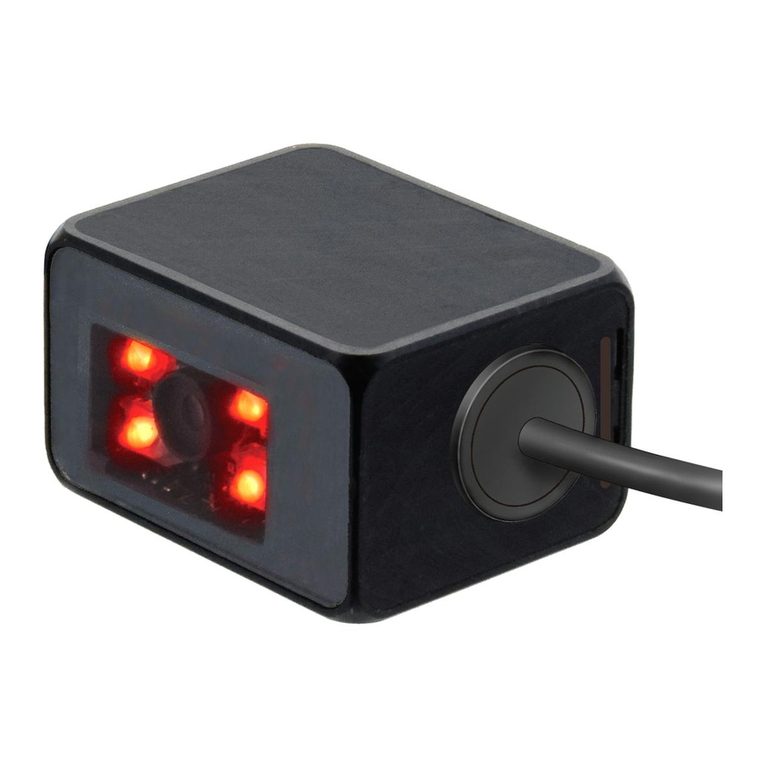
WB2F 2D Code Scanner
User’s Manual

i
Introduction
Attention
zIDEC Corporation holds all rights related to this manual. Unauthorized duplication, reproduction, sales, transfers, or leas-
ing without the express consent of IDEC is prohibited.
zInformation contained in this manual may be changed or updated without notice.
zEvery eort has been made to ensure the accuracy of the information contained in this manual. However, if you do note
any errors or inconsistencies please contact the dealer from which you purchased the product or an IDEC sales repre-
sentative.
Applicable standards
This product is in compliance with the following standards:
zIEC/EN 61000-6-1 (2007)
zIEC 62471 (2006)
zIEC 61000-6-3 (2006)
zEN 61000-6-3 (2007)
zEN 55032 (2012) Class A
zEN 55024 (2010)
zUL 60950-1, 2nd Edition, 2011-12-19
zFCC Part 15 Subpart B Class A (Verication)
zCSA C22.2 No.60950-1
zICES-003 Class A (self-declared)
zVCCI Class A (compliance conrmed)
FCC Regulations
This device complies with Part 15 of the FCC Rules. Operation is subject to the following two conditions:
(1) This device may not cause harmful interference, and
(2) this device must accept any interference received, including interference that may cause undesired
operation.
NOTE: This equipment has been tested and found to comply with the limits for a Class A digital device, pursuant to
Part 15 of the FCC Rules. These limits are designed to provide reasonable protection against harmful interference
when the equipment is operated in a commercial environment. This equipment generates, uses and can radiate
radio frequency energy and, if not installed and used in accordance with the instruction manual, may cause
harmful interference to radio communications. Operation of this equipment in a residential area is likely to cause
harmful interference in whitch case the user will be required to correct the interference at his own expense.
Canadian Department of Communications Compliance Statement
• CAN ICES-3(A) / NMB-3(A)
For further details on any of the above standards, please contact your sales agent directly.

2. Installation & wiring 3. Functions 4. Support tool 5. Appendix1. Overview
ii
Introduction
Version Information
The following is the latest version information for the WB2F 2D Code Scanner. Prior to use, conrm the main application
version of the rmware currently installed on the WB2F.
To conrm the rmware version currently installed on the WB2F, refer to "No. 46 Main Application Version Information" of
[5.6 List of Control Commands] located on page 5-20.
Fixes and Improvements Main application version
WB2F-100S1B
Initial Release A-001.000.00

2. Installation & wiring 3. Functions 4. Support tool 5. Appendix1. Overview
iii
Introduction
General terms, abbreviations, and terminology used in this manual
The general terms, abbreviations, and terminology used in this manual are as follows.
Item Denition
WB2F An abbreviation for the WB2F-100S1B.
Communication interface RS-232 Serial Communication Interface
Communication Unit
Refers to the Communication Unit WB9Z-CU100 available for purchase separately. The
WB9Z-CU100 is a protocol converter that allows the WB2F to connect to RS-232/RS-422/
Ethernet enabled devices.
Preventing Double Read
Time
A parameter that species a time interval between reads to prevent the WB2F from reading
the same code twice.
Number of characters The sum of 1 byte codes either transmitted or received via the RS-232 interface.
AIM ID An abbreviation for AIM Symbology Identier
AI An abbreviation for Application Identier (standardized by GS1)
Pitch Rotation of the symbol around the y-axis. Refer to F[5. 2. 3 Angle Characteristics] on
page 5-5.
Skew Rotation of the symbol around the x-axis. Refer toF[5. 2. 3 Angle Characteristics] on page
5-5.
Tilt Rotation of the symbol around the z-axis. Refer toF[5. 2. 3 Angle Characteristics] on page
5-5.
Reading Timeout A parameter that species the maximum time the WB2F will spend on reading a symbol.
Decode Timeout A parameter that species the maximum time the WB2F will spend on a decode processing.
Receive Buer A storage area that temporarily stores received data.
Send buer A storage area that temporarily stores transmission data.
Quiet Zone Blank region that surrounds the symbol
Control characters ASCII codes 00H - 1FH and 7FH. In this manual, they are expressed using . For details, refer
to F[5. 9 ASCII Code Table] on page 5-22.
Prex Character data that is added to the beginning of output data and communication com-
mands.
Sux Character data that is added to the end of output data and communication commands.
Output Depending on the context, refers to the following: External Output, Communication Out-
put, Status LED
Input Depending on the context, refers to the following: READ/ENTER button, SELECT button, Ex-
ternal Input, Communication Input
DPM An abbreviation for Direct Part Marking. A process used to directly mark parts made out of
materials such as metal and resin with product information such as 2D codes.
IDEC website www.idec.com

2. Installation & wiring 3. Functions 4. Support tool 5. Appendix1. Overview
iv
Introduction
Graphic Symbol Glossary
This manual uses the following graphic symbols to simplify explanations:
Notes
Graphic Symbol Description
WarningWarning
Failure to operate the product in accordance with the information provided may result in severe per-
sonal injury or death.
CautionCaution
Failure to operate the product in accordance with the information provided may result in personal
injury or damage to equipment.
Notes information that should be carefully noted. Failure to operate the product in accordance with
the information provided may aect the appearance and performance of the main unit as well as any
peripheral devices.
Denotes additional information that may prove useful for using a given function.
Status LED/Position Display LED
Graphic Symbol Description
(*) Indicates that the LED is turned OFF
(*) Indicates that the LED is turned ON
(*) Indicates that the LED is Flashing
* In case of Status LED, color will change based on status (green/orange/red). In case of Position LED, a number denoting
position (1/2/3/4) will be shown. In addition, the color of the graphic symbol will be drawn in accordance with the color
of the LED.

2. Installation & wiring 3. Functions 4. Support tool 5. Appendix1. Overview
v
Introduction
SAFETY PRECAUTATIONS
zBefore installing and wiring this product, operating it, or performing maintenance and inspection, read this manual
carefully and use the product correctly.
zThe degree of possible danger that may occur if the product is mishandled is classied and denoted by "Warning"
and "Caution" symbols. The meaning of each is as follows.
WarningWarning
Failure to operate the product in accordance with the information provided may result in severe
personal injury or death.
CautionCaution
Failure to operate the product in accordance with the information provided may result in per-
sonal injury or damage to equipment.
Safety precautions
WarningWarning
zThis product was not designed for use in applications that require a high safety and reliability
standard such as in medical equipment, equipment related to nuclear power, transportation
equipment and devices related to rail, aviation and automotive products. Please do not use
this product for these and/or similar applications.
zWhen using this product in applications that may impact human life, such as in the manage-
ment of chemicals, only do so after taking the utmost care to include all redundancies, fail-
safes and safety features into the design so as to ensure that human life is not impacted even
if data is mistaken.
zDo not modify, disassemble, or attempt to repair this product. Doing so may result in electri-
cal shock, damage, re, malfunctions and other other serious accidents.
zWhen using this product in situations where it is not built into other equipment, do not use
an integrated power supply. Otherwise there is a risk of re or electric shock.
zDo not look directly at the scan window or direct the scanner towards other people's eyes
while the LED light is on. There is a risk of causing damage to the eyes.
zThis product has been designed for use in general electronic equipment only. It is not autho-
rized for use in applications that require a high safety/reliability standard where malfunction
or failure of the product may result in severe personal injury or death.
zAlways turn the power supply o before performing any wiring, or mintenance work. Failure
to do so may result in electric shock or malfunction.

2. Installation & wiring 3. Functions 4. Support tool 5. Appendix1. Overview
vi
Introduction
CautionCaution
zDo not connect the product to a power supply outside the rated power supply voltage range
or to an AC power supply. Otherwise there is a risk of explosion or burnout.
zMistakenly wiring the product may cause the internal circuit to be damaged. Wire the input
and output circuits by referring to the connection examples in F P. 2-5 "2. 3. 1 Wiring the RS-
232 type". This product is not equipped with a protection circuit for a reversed power supply
connection, so there is a risk of damage when the power supply connection is reversed. Use
extreme caution when connecting the power supply.
zAvoid parallel wiring of the product's wires in the same conduit or duct with high voltage
lines or power lines (inverter power lines in particular) as this may cause malfunction or dam-
age due to the eect of induction noise.
zIf the wires are long and when there is a risk of being aected by power sources or solenoids,
independently wire the product as a general rule.
zAvoid installing or using the product in the following locations as there is a risk of malfunc-
tion or damage.
-Near induction equipment or heat sources
-Locations with many vibrations or shocks
-Dusty and dirty locations
-In an atmosphere with hazardous gases such as suldizing gas
-Locations in direct contact with water, oils, or chemicals
-Outdoors
zThis product is not an explosion-proof product. Conrm that explosion-proof capabilities are
not required when installing the product.
Precautions for Use
CautionCaution
zUse the product in the environment listed in the catalog and manual. If this product is used
in locations with high temperatures, high humidity, condensation, corrosive gas, or excessive
vibration/shock, there is a risk of electric shock, re, and malfunction.
zThe usage environment pollution degree for this product is "pollution degree 2". Use the
product in a pollution degree 2 environment.
(Based on the IEC 60664-1 standard)
zThe power reset time is under 5s. Perform operations 5s after turning the power on.
zWhen the load and the unit are connected to dierent power supplies, always turn on the unit's power
supply rst.
zInstall the product so that the scan window is not directly exposed to sunlight or uorescent light.
zThe non-volatile memory equipped on the WB2F can be overwritten 100,000 times.

2. Installation & wiring 3. Functions 4. Support tool 5. Appendix1. Overview
vii
Introduction
Cleaning
zCleaning the Scan Window
Keep the scan window free of dust, dirt, moisture and scratches as it will negatively
aect scanning performance.
Inspect the scan window periodically and remove any dirt or dust that may have
accumulated.
Cleaning methods
zTo clean the scan window, blow the dust/dirt away with an airbrush, and then gently wipe it o with a cotton swab or a
similarly soft object.
zIf moisture has collected on the scan window, wipe with a soft cloth.
zAlways turn the WB2F power o before cleaning the product.
Do not use organic solvents such as alcohol, thinner or benzene as they may aect the optics of the WB2F.
zCleaning the unit
zWipe any dust or dirt o of the WB2F with a soft, dry cloth.
zIf the product is excessively dirty, wipe the surface with a soft cloth that has been soaked in a dilute neutral detergent
solution and thoroughly wrung out. Dry with a soft dry cloth.
Do not use organic solvents such as alcohol, thinner, or benzine as this may alter the housing or strip the
paint.
Scan Window

2. Installation & wiring 3. Functions 4. Support tool 5. Appendix1. Overview
viii
Introduction
Related manuals
Manuals related to the WB2F are as follows. Refer to them together with this manual.
All related manuals are available for download from our website.
Type Manual name Details
B-1952 WB2F 2D Code Scanner
User’s Manual (this manual)
Gives an overview of the functions and capabilities of the
WB2F, and instructions on its use.
B-1945 Instruction Sheet:
WB2F 2D Code Scanner Included with the product.
B-1946 Instruction Sheet:
WB9Z-CU100 Communication Unit Included with the product.
B-1963 WB9Z-CU100 Communication Unit
User’s Manual
Gives an overview of the functions and capabilities of the
communication unit as well as instructions on its use.

ix
Introduction i
Attention..............................................................................................................................................................i
Applicable standards.......................................................................................................................................i
Version Information ........................................................................................................................................ii
General terms, abbreviations, and terminology used in this manual..........................................iii
Graphic Symbol Glossary .............................................................................................................................iv
Notes..................................................................................................................................................................................... iv
Status LED/Position Display LED................................................................................................................................. iv
SAFETY PRECAUTATIONS ..............................................................................................................................v
Safety precautions .............................................................................................................................................................v
Precautions for Use.......................................................................................................................................................... vi
Cleaning.............................................................................................................................................................................. vii
Related manuals........................................................................................................................................... viii
Contents ix
1
Overview 1-1
1. 1 Checking the packaged product and the product conguration...............................1-1
1. 2 Part names and functions ..........................................................................................................1-2
1. 3 System conguration ..................................................................................................................1-3
1. 4 Accessories and Peripheral Devices .......................................................................................1-5
2
Installation & wiring 2-1
2. 1 Installation precautions..............................................................................................................2-1
2. 2 Mounting methods ......................................................................................................................2-3
2. 2. 1 WB2F mounting methods ..................................................................................................................... 2-3
2. 2. 2 Setup symbol position............................................................................................................................ 2-4
2. 3 Wiring................................................................................................................................................2-5
2. 3. 1 Wiring Instructions: Connecting the WB2F to the Communication Unit ............................. 2-5
2. 3. 2 Wiring Instructions: Setting up the WB2F without the Communication Unit..................2-12
2. 3. 3 Connecting the USB Cable..................................................................................................................2-15
Contents

2. Installation & wiring 3. Functions 4. Support tool 5. Appendix1. Overview
x
Contents
3
Operational Check 3-1
3. 1 Performing an Operational Check using a PC ....................................................................3-1
3. 1. 1 Necessary operating environment of the PC ................................................................................ 3-1
3. 1. 2 Installing the Device Driver................................................................................................................... 3-1
3. 1. 3 Connecting to a PC .................................................................................................................................. 3-2
3. 2 Conrming a Successful Read ..................................................................................................3-3
3. 3 Symbol Read Data Conrmation.............................................................................................3-4
4
Function 4-1
4. 1 Overview ..........................................................................................................................................4-1
4. 1. 1 Operation mode........................................................................................................................................ 4-1
4. 1. 2 Operation mode switching operation and status......................................................................... 4-3
4. 2 Slave Mode......................................................................................................................................4-4
4. 2. 1 Switching operation to slave mode................................................................................................... 4-4
4. 2. 2 Symbol reading......................................................................................................................................... 4-5
4. 2. 3 Output data additional information................................................................................................4-15
4. 2. 4 Output data editing...............................................................................................................................4-20
4. 2. 5 Verication ................................................................................................................................................4-22
4. 2. 6 Command alias........................................................................................................................................4-26
4. 2. 7 Communication command.................................................................................................................4-28
4. 2. 8 Parameter Changeover.........................................................................................................................4-31
4. 2. 9 Image Capture .........................................................................................................................................4-34
4. 2. 10 Image Filter...............................................................................................................................................4-37
4. 2. 11 I/O.................................................................................................................................................................4-40
4. 3 Setup support mode................................................................................................................. 4-41
4. 3. 1 Switching operation to setup support mode...............................................................................4-41
4. 3. 2 Reading Success Rate Measurement...............................................................................................4-44
4. 3. 3 Decoding Processing Time Measurement.....................................................................................4-45
4. 3. 4 Symbol Position Measurement..........................................................................................................4-46
4. 3. 5 Autotuning................................................................................................................................................4-48
4. 4 Maintenance mode ................................................................................................................... 4-50
4. 4. 1 Switching operation to maintenance mode.................................................................................4-50
4. 4. 2 Maintenance support............................................................................................................................4-52
4. 4. 3 Firmware updating.................................................................................................................................4-52
4. 5 Master Mode................................................................................................................................ 4-53
4. 5. 1 Switching to Master Mode ..................................................................................................................4-53
4. 5. 2 Connecting to a PLC ..............................................................................................................................4-53

2. Installation & wiring 3. Functions 4. Support tool 5. Appendix1. Overview
xi
Contents
4. 6 Conguration Item Table......................................................................................................... 4-54
4. 7 Communication Unit ................................................................................................................ 4-93
4. 7. 1 Overview....................................................................................................................................................4-93
4. 7. 2 Names and functions of its parts ......................................................................................................4-94
5
Appendix 5-1
5. 1 Product specications.................................................................................................................5-1
5. 2 Field of view/characteristics......................................................................................................5-3
5. 2. 1 Reading Range........................................................................................................................................... 5-3
5. 2. 2 Field of View................................................................................................................................................ 5-4
5. 2. 3 Angle Characteristics............................................................................................................................... 5-5
5. 3 Dimensional outline drawings.................................................................................................5-7
5. 4 Troubleshooting............................................................................................................................5-9
5. 5 Timing Chart ................................................................................................................................ 5-10
5. 5. 1 Scan Operation Timing Chart.............................................................................................................5-10
5. 5. 2 External Output Timing Chart............................................................................................................5-11
5. 6 List of Control Commands ...................................................................................................... 5-13
5. 7 Control Commands (Details).................................................................................................. 5-17
5. 8 Check digit calculation method............................................................................................ 5-21
5. 9 ASCII Code Table......................................................................................................................... 5-22
5. 10 AIM symbology ID table .......................................................................................................... 5-24
5. 11 GS1-128 Application Identier.............................................................................................. 5-26
5. 12 Initialization Barcode................................................................................................................ 5-27
5. 13 Sample labels............................................................................................................................... 5-28
5. 14 Installing the USB driver .......................................................................................................... 5-31
5. 15 Setting check digit..................................................................................................................... 5-32
Index A-1
Revision history A-3

1-1
1
Overview
This chapter describes the product conguration of the WB2F, the names and functions of its parts, and the basic system
conguration during operation.
1. 1
Checking the packaged product and the product conguration
The WB2F is packaged with the following items:
Before using the WB2F, check that the unit and accessories are present and that they have suered no damage.
Unit: 1
Mounting screws (M3): 2
the WB2F is shipped with the
mounting screws attached
Mounting Bracket: 1
Instruction Manual: 1
WB2F 2D Code Scanner
INSTRUCTION SHEET

2. Installation & wiring 3. Operational Check 4. Support tool 5. AppendixOverview
1-2
Part names and functions
1. 2 Part names and functions
This section describes the names and functions of WB2F parts.
(1)Scan Window
(2)Emitter LED
(10)Maintenance Port (USB)
(6)Status LED
(5)Power-ON
Indicator LED
(7)Position LED
(4)READ/ENTER button
(3)SELECT button
(9)Connector
(8)Connecting cable
Scanner
Reading
Surface
Scanner
Operational
Surface
No. Description Function
(1) Scan Window The window protects the optical components of the WB2F from dust, debris and mois-
ture.
(2) Emitter LED Lights up during scan operation (based on settings, this is not the only time it will light
up) Lighting modes, the number of LEDs that light up etc. can be altered via settings.
(3) SELECT button Used to select various functions
(4) READ/ENTER button Used to conrm various functions that have been selected
(5) Power-ON Indicator LED Green LED will light up when the WB2F's power is on
(6) Status LED
The Status LED indicates the operating status of the unit.
(Green): Turns on when reading has succeeded and the read image is matched on com-
parison.
(Orange) : Turns on during a reading operation.
(Red): Turns on when reading fails and the read image is not matched on comparison.
This operation may dier due to the settings.
The status of the Status LEDs also changes due to the unit's operating status.
(7) Position LED Displays the Position of the symbol. (1) - (4): The position of the symbol placed in the
WB2Fs FOV will light up on the LED display.
(8) Connecting cable Cable length: 2 m
(9) Connector
DIN Connector (manufactured by Hosiden, TCP9386, Male) used to provide power to the
WB2F, or connect to the communication unit.
(10) Maintenance Port (USB)
Port that utilizes the USB interface to perform various maintenance operations (USB 2.0,
Mini-B). If connecting to a host device, use its accessory or any commercially available
USB cable.

2. Installation & wiring 3. Operational Check 4. Support tool 5. AppendixOverview
1-3
System conguration
1. 3 System conguration
The typical system conguration when operating the WB2F is as follows.
With the Communication Unit
WB2F
PC
Communication Unit
Sensor
PLC, External Light Source
Host device
24V DC Power Supply
24V DC
Power Supply
5V DC power supply
RS-232
I/Os
(DIN Connector)
External Output
RS-232
RS-422
Ethernet External Input
USB
(for Maintenance
Purposes)
The device driver must be installed prior to connecting the WB2F to a PC via USB. Refer to F[5. 14 Installing
the USB driver] on page 5-31 for installation instructions.

2. Installation & wiring 3. Operational Check 4. Support tool 5. AppendixOverview
1-4
System conguration
Without the Communication Unit
WB2F
Sensor
Host device
5V DC Power Supply
5V DC Power Supply
External Input
USB
(for Maintenance
Purposes)
PLC, External Light Source
RS-232
PC
External Output
The device driver must be installed prior to connecting the WB2F to a PC via USB. Refer to F[5. 14 Installing
the USB driver] on page 5-31 for installation instructions.

2. Installation & wiring 3. Operational Check 4. Support tool 5. AppendixOverview
1-5
Accessories and Peripheral Devices
1. 4 Accessories and Peripheral Devices
The WB2F's accessories and peripheral devices are as follows:
zAccessories
USB Maintenance Cable
HG9Z-XCM42
zPeripheral Devices
WB2F compatible communication unit
WB9Z-CU100

2-1
2
Installation & wiring
This chapter describes WB2F installation locations, mounting methods, and wiring the WB2F to peripheral devices.
2. 1 Installation precautions
zInstall the unit so that ambient light such as sunlight, uorescent light, and photoelectric switches does not enter the
scan window.
Otherwise the unit may not be able to read symbols or it may erroneously read them.
Example Take measures to block ambient light or to change the position of photoelectric switches.
Block
the light
zDo not install a reective body (metal or mirror) along the light receiving axis.
Otherwise the unit may not be able to read symbols or it may erroneously read them.
Example Tape over any mirrored/reective surfaces with black tape to prevent the reection of light.
Field of view
Black tape
Mirror

Installation & wiring 3. Operational Check 4. Function 5. Appendix1. Overview
2-2
Installation precautions
zWhen installing WB2F units in a series, install them so the emitted LED light does not overlap (so they do not interfere
with each other).
Otherwise the unit may not be able to read symbols or it may erroneously read them.
Example Install the WB2F units by increasing the spacing between them.
Interference

Installation & wiring 3. Operational Check 4. Function 5. Appendix1. Overview
2-3
Mounting methods
2. 2 Mounting methods
2. 2. 1 WB2F mounting methods
1 Double check the dimensions of the mounting hole and drill a hole in the mounting board
For the dimensions of the mounting hole, refer to F[5. 3 Dimensional outline drawings] on page 5-7.
2 If you use the brackets provided, use the two mounting screws (also provided) to secure the bracket to the
WB2F before you secure the bracket to the mounting board.
If you do not use the brackets provided, use the two mounting screws to secure the WB2F to the mounting
board.
The tightening torque for the product mounting screws is 0.4 to 0.5 N·m.
Mounting Screws (Included)
M3 SEMS x 6 (2 screws)
Mounting Bracket
(Included)
zInstead, use two M3 screws with an eective thread length of 3 to 5 mm and secure the WB2F to the
plate.
zIf you use a bracket other than the one that was included, make sure that the dimensions of the
mounting holes is at most Φ3.4mm
zWhen using the WB2F, remove the protective lm on the scan window.
zIf you attach to a plate that is thicker than 2.3 mm, do not use the included mounting screws.
zIf, during installation, the WB2F is exposed to excessive force (e.g. the mounting screws are
tightned excessively, the product is hit with a hammar, the base of the cable is exposed to exces-
sive stress (pulled strongly, bent etc.)), it could undermine the IP65 protective structure of the
WB2F.
Other manuals for WB2F
2
Table of contents
Other IDEC Barcode Reader manuals
