IDEC WB2F User manual

B-1956(3)
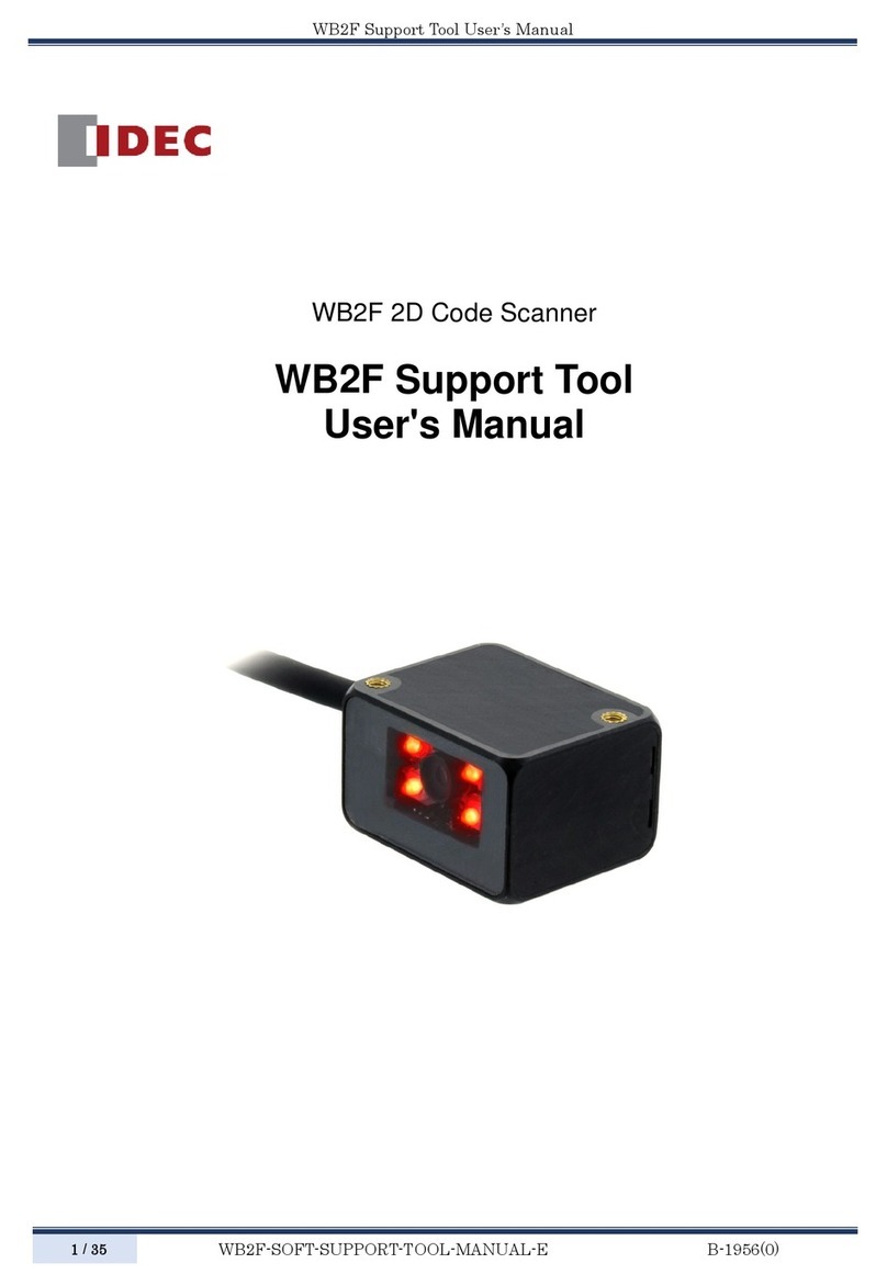
WB2F 2D Code Scanner
WB2F Support Tool
User’s Manual

i
Introduction
This document is the user’s manual for the WB2F Support Tool, a support tool for the WB2F 2D code scanner. The WB2F
Support Tool is provided “as- is” free of charge, whether express or implied, without warranty of any kind. This includes,
but is not limited to, merchantability, compatibility for specic purposes, non-defect, and non-infringement of third party
rights. You may operate this support tool only under your responsibility. IDEC Corporation (“IDEC”) will not be responsi-
ble for any damage whatsoever, including but not limited to, consequential damage, indirect damage, special damage,
incidental damage, loss of prot, business interruptions, loss of business information, and other monetary damages that
occur from the use or the inability to use this support tool, even if IDEC is informed of the possibility of such damages.
Before using the WB2F Support Tool, please read this manual and understand the specications of the software so that is
can be used correctly.
Attention
zIDEC Corporation holds all rights related to this manual. Unauthorized duplication, reproduction, sales, transfers, or leas-
ing without the express consent of IDEC is prohibited.
zThe content of this manual may change without prior notication.
zWe have taken all possible measures with the content of this product, but if you notice any portions that are unclear, or
any mistakes, please contact the dealer where purchased or an IDEC sales representative.

2 Operational Check 3 Screen and Menu 4 Appendix1 Overview
ii
Introduction
Terms of use
Software End User License Agreement
Important
Carefully read the following license agreement.
This agreement, regarding this software product (hereinafter called "this software") which you are in possession of,
is a legal agreement that is concluded between the customer (individual or corporation) and the IDEC Corporation
(hereinafter called "IDEC"). This software may include computer software and related media, printed materials
(manuals and other documents) as well as "online" or electronic documents. By installing, copying or using this software,
the customer is regarded to agree to the terms of this agreement. If you do not agree to the terms of this agreement, IDEC
cannot grant the customer permission to install, use, or copy this software product.
1. SCOPE
When the customer uses this software, the conditions of its application are as follows.
(1) GRANT. Without any charge, IDEC CORPORATION (IC) hereby grants to you a non-exclusive license to use its
accompanying software product and accompanying documentation (Software).
(2) You may: copy the Software for archival purposes, provided any copy must contain all of the original Software's
proprietary notices.
(3) You may not: copy the Software (except as specied above); rent, lease, sell, transfer or otherwise transfer rights
to the Software; permit other individuals to use the Software except under the terms listed above; or remove any
proprietary notices or labels on the Software.
(4) IDEC does not guarantee the absence of aws, compatibility, operability, usability, and non-infringement of this
software. Additionally, IDEC bears absolutely no responsibility for any and all types of loss including loss of trust,
suspension of operations, hardware failure, and all other commercial loss whether direct or indirect.
2. PROHIBITIONS
2.1. You may not: permit other individuals to use the Software except under the terms listed above; modify, translate,
reverse engineer, decompile, disassemble (except to the extent applicable laws specically prohibit such restriction),
or create derivative works based on the Software.
2.2. Use of this software for prot-making purposes is forbidden.
2.3. The use of content for this software to conduct illegal or improper behavior is forbidden.
2.4. EXPORT CONTROLS. None of the Software or underlying information or technology may be downloaded or
otherwise exported or reexported (i) into (or to a national or resident of ) Iraq, Libya, North Korea, Iran or any other
country to which the U.S. has embargoed goods; or (ii) to anyone on the U.S.Treasury Department's list of Specially
Designated Nationals or the U.S. Commerce Department's Table of Deny Orders.
2.5. In the event that the customer is in violation of this agreement or prohibited items resulting in damage to IDEC,
IDEC can bill the user in question for compensation for damages and recovery measures, as well as conscate this
software and/or take any other actions deemed necessary.
3. MISCELLANEOUS
3.1. TITLE. Title, ownership rights, and intellectual property rights in and to the Software shall remain in IC and/or
its suppliers. The Software is protected by the copyright laws of the United States and international copyright
treaties. If you receive your first copy of the Software electronically, and a second copy on media, the second
copy may be used for archival purposes only. Title, ownership rights, and intellectual property rights in and to the
content accessed through the Software is the property of the applicable content owner and may be protected by
applicable copyright or other law. This License gives you no rights to such content.
3.2. Checking the environment in which this software will be installed and ensuring data retention through backup and
other such actions are the sole responsibility of the customer.

2 Operational Check 3 Screen and Menu 4 Appendix1 Overview
iii
Introduction
3.3. This agreement contains the entire agreement between the parties pertaining to the licensing of this software and
supersedes all prior agreements and understandings. Revision of this agreement is only performed in writing that is
concluded by both parties.
3.4. The governing law of this agreement is the law of Japan.

2 Operational Check 3 Screen and Menu 4 Appendix1 Overview
iv
Introduction
Version up information
The following table gives information about the versions of the WB2F Support Tool. Check the software version and data-
base version before using the software.
For how to check the version, refer to F[Version information] on page 3-15 of [3. 3. 5 Help].
Details WB2F Support Tool Version
Software Version Database Version
Initial release 001.000.00 001.000.00
Support for WB2F type rmware A-001.011.00 001.011.00 001.011.00
Support for WB2F type rmware A-001.020.00 001.020.00 001.020.00
Support for WB2F type rmware A-002.000.00 002.000.00 002.000.00
General terms, abbreviations, and terminology used in this manual
The general terms, abbreviations, and terminology used in this manual are as follows.
Item Denition
WB2F An abbreviation for the WB2F-100S1B.
Communication unit
Refers to the Communication Unit WB9Z-CU100 available for purchase separately. The
WB9Z-CU100 is a protocol converter that allows the WB2F to connect to RS-232/RS-422/
Ethernet enabled devices.
Quiet zone Blank region that surrounds the symbol.
Control characters ASCII codes 00H - 1FH and 7FH. In this manual, they are expressed using . For details,
refer to F[4. 2 ASCII Code Table] on page 4-4.
RAM An abbreviation for random access memory. RAM is used to read and write temporary data.
The data is erased when the WB2F power supply is turned o.
ROM An abbreviation for read only memory. ROM is used to read data only. The data is not erased
when the WB2F power supply is turned o.
Our website www.idec.com/
Graphic Symbol Glossary
This manual uses the following graphic symbols to simplify explanations:
Notes
Graphic symbols Meaning
Notes information that should be carefully noted. Failure to operate the product in accordance
with the information provided may aect the performance of the main unit as well as any connect-
ed peripheral devices.
Denotes additional information that may prove useful for using a given function.

2 Operational Check 3 Screen and Menu 4 Appendix1 Overview
v
Introduction
Related manuals
Manuals related to the WB2F are as follows. Refer to them together with this manual.
All related manuals are available at our website. Download the latest manuals from our website.
Type Manual name Details
B-1956
WB2F 2D Code Scanner
Support Tool
User’s Manual (this manual)
Included with the WB2F Support Tool.
Explains about the support tool.
B-1945 Instruction Sheet:
WB2F 2D Code Scanner Included with the product.
B-1946
Instruction Sheet:
Communication Unit Supporting Code Scanner
WB9Z-CU100
Included with the product.
B-1952 WB2F 2D Code Scanner
User’s Manual
Gives an overview of the functions and capabilities
of the WB2F, and instructions on its use.
B-1956
WB2F 2D Code Scanner
WB2F Support Tool
User's Manual
Included with the support tool for WB2F. Explains
about support tool.
B-1960
WB2F 2D Code Scanner
PLC Connection
User’s Manual
Explains about PLC Connection.
B-1962 WB2F 2D Code Scanner
Menu Sheet Explains about menu sheet.
B-1964
Communication Unit Supporting Code Scanner
WB9Z-CU100
User’s Manual
Gives an overview of the functions and capabilities
of the communication unit as well as instructions on
its use.
B-2024
Communication Unit Supporting Code Scanner
WB9Z-CU100
PLC Connection
User’s Manual
Explains the communication unit-based PLC
connection Function.
B-1968
Communication Unit Supporting Code Scanner
WB9Z-CU100
Support Tool
User’s Manual
Included with the support tool for the communica-
tion unit. Explains about the support tool.
B-2124
Communication Unit Supporting Code Scanner
WB9Z-CU100
CC-Link IE Field Basic Function
User’s Manual
Explains about the CC-Link IE Field Basic Function.
B-2127
Communication Unit Supporting Code Scanner
WB9Z-CU100
EtherNet/IP Function
User’s Manual
Describes the EtherNet/IP Function.
B-2130
Communication Unit Supporting Code Scanner
WB9Z-CU100
Support Tool Version 2
User’s Manual
Included with the support tool version 2 for the
communication unit.
Explains about the support tool version 2.

vi
Introduction i
Attention..............................................................................................................................................................i
Terms of use.......................................................................................................................................................ii
Version up information.................................................................................................................................iv
General terms, abbreviations, and terminology used in this manual..........................................iv
Graphic Symbol Glossary .............................................................................................................................iv
Notes..................................................................................................................................................................................... iv
Related manuals...............................................................................................................................................v
Contents vi
1
Overview 1-1
1. 1 Overview..........................................................................................................................................1-1
1. 2 Usage Precautions ........................................................................................................................1-1
2
Operational Check 2-1
2. 1 System Requirements..................................................................................................................2-1
2. 2 Setup .................................................................................................................................................2-2
2. 2. 1 Installing the support tool..................................................................................................................... 2-2
2. 2. 2 Uninstalling the support tool............................................................................................................... 2-2
2. 3 Operation Conrmation Method ............................................................................................2-3
2. 3. 1 Checking the interface ........................................................................................................................... 2-3
2. 3. 2 Installing the device driver.................................................................................................................... 2-3
2. 3. 3 Connecting the WB2F to the computer ........................................................................................... 2-3
2. 3. 4 Starting the WB2F Support Tool.......................................................................................................... 2-5
2. 3. 5 Reading symbols....................................................................................................................................... 2-5
Contents

2 Operational Check 3 Screen and Menu 4 Appendix1 Overview
vii
Contents
3
Screen and Menu 3-1
3. 1 Screen Conguration...................................................................................................................3-1
3. 1. 1 Menu ............................................................................................................................................................. 3-1
3. 1. 2 Function screen area ............................................................................................................................... 3-1
3. 1. 3 Basic command buttons ........................................................................................................................ 3-2
3. 1. 4 Console......................................................................................................................................................... 3-2
3. 1. 5 Image monitor........................................................................................................................................... 3-3
3. 1. 6 Monitor for reading result ..................................................................................................................... 3-3
3. 2 Menu Items List .............................................................................................................................3-4
3. 3 Menu Item Descriptions .............................................................................................................3-5
3. 3. 1 File.................................................................................................................................................................. 3-5
3. 3. 2 Function ....................................................................................................................................................... 3-6
3. 3. 3 Tool ..............................................................................................................................................................3-15
3. 3. 4 Language...................................................................................................................................................3-15
3. 3. 5 Help .............................................................................................................................................................3-15
4
Appendix 4-1
4. 1 Troubleshooting............................................................................................................................4-1
4. 1. 1 Cannot connect to the WB2F Support Tool..................................................................................... 4-1
4. 1. 2 Communication port is not displayed .............................................................................................. 4-1
4. 1. 3 Cannot connect to the WB2F Support Tool
because the WB2F RS-232 settings were forgotten ..................................................................... 4-2
4. 2 ASCII Code Table............................................................................................................................4-4
Index A-1
Revision history A-2

1-1
1
Overview
This chapter provides an overview of the WB2F Support Tool and usage precautions.
1. 1 Overview
The WB2F Support Tool is software for conguring the WB2F and checking its operation.
1. 2 Usage Precautions
In order to use the support tool correctly, please be aware of the following precautions.
zWhen the WB2F and the WB2F Support Tool are connected, do not turn o the WB2F power supply.
The WB2F Support Tool may be forcibly terminated.
After stopping the connection between the WB2F and the WB2F Support Tool, turn o the WB2F power supply.
zWhen the WB2F and the WB2F Support Tool are connected, do not allow the computer to enter sleep mode. The WB2F
Support Tool may be forcibly terminated.
If the WB2F and the WB2F Support Tool are connected and left for a long period of time, congure the computer so that
it does not enter sleep mode.
zDo not run multiple instances of the WB2F Support Tool at the same time. The support tool may not operate correctly.

2-1
2
Operational Check
This chapter describes the system requirements, setup, and how to test operation of the WB2F Support Tool.
2. 1 System Requirements
This table shows the WB2F Support Tool system requirements.
Item Details
PC PC-AT or compatible
OS Windows 7 (32-/64-bit), Windows 8 (32-/64-bit),
Windows 8.1 (32-/64-bit), Windows 10 (32-/64-bit)
CPU 1.0 GHz or higher
Memory 1 GB or higher
Hard disk 100 MB or higher
Screen resolution WXGA (1366×768) or higher
Communication port RS-232 port
USB port (USB 2.0 or higher)
*Microsoft and Windows are registered trademarks or trademarks of Microsoft Corporation in the United States and/or
other countries.

2 Operational Check 3 Screen and Menu 4 Appendix1 Overview
2-2
Setup
2. 2 Setup
2. 2. 1 Installing the support tool
To use the support tool, it must be installed on a computer. Do so with the following procedure.
Unzip the compressed“wb2f_support_tool_***_***_**-*.zip”le to the desktop or any desired location.
After you unzip the le, double-click “wb2f_support_tool.exe” in the “wb2f_support_tool_***_***_**-*” folder to run the
support tool. The support tool may not run correctly if the les in the folder are deleted or moved. (***_***_**-* indicates
the version number.)
2. 2. 2 Uninstalling the support tool
When you no longer need the support tool, it must be uninstalled from the computer. Do so with the following proce-
dure.
Delete the entire folder (including the files) that was created by unzipping the compressed “wb2f_support_
tool_***_***_**-*.zip” le. The support tool does not use the registry, so you will not need to delete any registry entries.
(***_***_**-* indicates the version number.)

2 Operational Check 3 Screen and Menu 4 Appendix1 Overview
2-3
Operation Conrmation Method
2. 3 Operation Conrmation Method
In this section you will read symbols with the WB2F using the WB2F Support Tool.
The example here shows the WB2F in its factory default state when no settings have been changed.
Note that the operation of the WB2F may be dierent if the settings have been changed.
2. 3. 1 Checking the interface
If you are using USB, proceed to F[2. 3. 2 Installing the device driver] on page 2-3.
If you are using RS-232, proceed to F[2. 3. 3 Connecting the WB2F to the computer] on page 2-3.
2. 3. 2 Installing the device driver
A device driver must be installed so the WB2F and WB2F Support Tool can communicate with each other. Download the
latest device driver installer from the IDEC website and use it to the install the device driver. For details on the installer,
check the readme that is included with the installer.
IDEC website: http://www.idec.com/
2. 3. 3 Connecting the WB2F to the computer
zConnection of USB connector
To connect to the host device, rmly insert the USB-A connector straight into the USB port on the host device in the cor-
rectorientation
Host device USB port
USB-A Connector
Connect the cable to the WB2F by opening the maintenance port (USB port) cover and rmly inserting the USB Mini-B
connector into the maintenance port (USB port) on the WB2F.
Maintenance Port
(USB Port)
USB Mini-B Connector
Power cannot be supplied to the WB2F from the USB connector. For how to wire and supply power to the
WB2F, refer to the WB2F user’s manual.

2 Operational Check 3 Screen and Menu 4 Appendix1 Overview
2-4
Operation Conrmation Method
zRS-232 connection
When using the communication unit
Wire the WB2F to the PC as shown in the diagram. After you nish wiring the WB2F and PC, turn on the 24-VDC power
supply.
If the PC is not equipped with a RS-232 port, please use a RS-232-to-USB conversion cable.
2RXD
Pin NumberDescription
3TXD
7RTS
8CTS
5GND
1DCD
4DTR
6DSR
9RI
Description
SD
RD
CS
RS
SG
Input/Output/RS-232/RS-422 port
Connector for Input/O
utput/
RS-232/RS-422 port
Connector for Input/Output/
RS-232/RS-422 port Host device
D-sub 9-pin connector
Do not reverse the power supply connections under any circumstances. Doing so may result in damage. Care-
fully read the user’s manual for the communication unit before wiring the WB2F.
When not using the communication unit
Wire the WB2F to the PC as shown in the diagram. After you nish wiring the WB2F and PC, turn on the 5-VDC power sup-
ply.
If the PC is not equipped with a RS-232 port, please use a RS-232-to-USB conversion cable.
2RXD
Pin NumberDescription
3TXD
7RTS
8CTS
5GND
1DCD
4DTR
6DSR
9RI
5V DC
Pin Number
6
Description
TXD
10 RXD
11 CTS
12 RTS
9 0V
5 +5V
D-sub 9-pin connector
WB2FHost device
Function
RS-232 Transmission Data
RS-232 Receive Data
RS-232 Control Signal
RS-232 Control Signal
Power Supply (- SG Shared)
Power Supply +
Do not reverse the power supply connections under any circumstances. Doing so may result in damage. Care-
fully read the user’s manual for the WB2F before wiring the WB2F.

2 Operational Check 3 Screen and Menu 4 Appendix1 Overview
2-5
Operation Conrmation Method
2. 3. 4 Starting the WB2F Support Tool
Double-click “wb2f_support_tool.exe”.
When you double-click the le, the Connection settings screen is displayed.
2. 3. 5 Reading symbols
1 Select the communication port that the WB2F is connected to.
2
1
4
How to check the communication port
zFor Windows 7
(1) Click Start, right-click Computer, and click Properties on the displayed menu.
The System screen is displayed.
(2) Click Device Manager at the top left of the screen.
The Device Manager screen is displayed.
(3) Double-click Ports (COM & LPT).
(4) For a USB connection, check the port number displayed as “IDEC Auto-ID WB2F USB CDC (COM**)”.
For an RS-232 connection, check the port number of the port to which the RS-232-to-USB connection cable is
connected.

2 Operational Check 3 Screen and Menu 4 Appendix1 Overview
2-6
Operation Conrmation Method
zFor Windows 8/8.1/10
(1) Press the Windows key and the Xkey.
(2) Click Device Manager on the displayed menu.
The Device Manager screen is displayed.
(3) Double-click Ports (COM & LPT).
(4) For a USB connection, check the port number displayed as “IDEC Auto-ID WB2F USB CDC (COM**)”.
For an RS-232 connection, check the port number of the port to which the RS-232-to-USB connection cable is
connected.
If the port number checked in “How to check the communication port” is not displayed in the commu-
nication port on the Connection settings screen
Close the WB2F Support Tool, cycle the power supply to the WB2F, and then start the WB2F Support Tool again.
2 After you select the communication port, click Connect automatically.
3 Check if the connection was successful or a failure.
zIf the connection was successful
Click OK and proceed to step 4.
3
zIf the connection was a failure
Click No and redo the procedure from step 1.
3
4 After a successful connection, click Function - Control command on the menu bar.
The Control command screen is displayed.

2 Operational Check 3 Screen and Menu 4 Appendix1 Overview
2-7
Operation Conrmation Method
5 Click read start to acquire a symbol.
5
6
6 The reading results are displayed.
“Requests (PC →WB2F)” are displayed as blue text. “Responses (WB2F →PC)” are displayed as red text.
When a symbol is successfully read, the reading results are returned as the response. When reading fails, “?” is re-
turned as the response. The following shows an example of reading a symbol.
Example: ASCII display example
^get・↲ Request: Click read start.
DataMatrix_0.50mm・↲ Response: Reading result“1234567890” (reading success)
^get・↲ Request: Click read start.
?・↲ Response: Reading result “?”(reading failure)
・↲
: Represents the ASCII control characters CR LF . Since the control characters cannot be displayed as
characters, they have been replaced with other characters. LF alone is displayed as “ ↲”, and the other
control characters are displayed as “・”. Check the control characters by switching to the HEX display mode.

3-1
3
Screen and Menu
This chapter describes the WB2F Support Tool screen and menu.
3. 1 Screen Conguration
The following screenshot shows the screen conguration of the WB2F Support Tool.
(5)
(6)
(1)
(2)
(3)
(4)
No. Name Description
(1) Menu Used to select and execute the various functions of this tool.
(2) Function screen area Displays the execution screen for the selected function.
(3) Basic command buttons Used to execute basic commands that control the unit and tool.
(4) Console Displays the communication log for the unit and tool.
(5) Image monitor Displays images.
(6) Monitor for reading result Displays the reading result.
3. 1. 1 Menu
The menu is used to select and execute the various functions of this tool.
For the menu items, refer to F[3. 2 Menu Items List] on page 3-4.
3. 1. 2 Function screen area
The function screen area displays the execution screen for the function selected from the menu.
For details on the functions, refer to F[3. 2 Menu Items List] on page 3-4.

2 Operational Check Screen and Menu 4 Appendix1 Overview
3-2
Screen Conguration
3. 1. 3 Basic command buttons
The basic command buttons are used to execute basic commands that control the unit and tool.
Button name Description
Receive
WB RAM→TOOL
Loads the current values of the WB2F into the tool.
Send
TOOL→WB RAM
Applies setting values edited in the tool to the WB2F.
Save
WB RAM→WB ROM
Saves the WB2F current values to the setting values area (non-volatile memory).
Load
WB ROM→WB RAM
Loads the setting values in the WB2F setting values area (non-volatile memory) and sets
them as the current values.
Clear Edit data Discards the setting values loaded into the tool.
Reset Resets the WB2F.
Initialize Initializes the WB2F.
3. 1. 4 Console
This area displays the console screen.
Use this screen when to enter commands yourself or to check detailed communication information.
You can use the console in a separate screen by double-clicking the title bar.

2 Operational Check Screen and Menu 4 Appendix1 Overview
3-3
Screen Conguration
3. 1. 5 Image monitor
The image monitor displays images.
It displays images captured and saved by the WB2F.
Button name Description
Repeat Snapshot Performs continuous imaging. Use this button when positioning the scanner.
Snapshot Performs imaging one time.
Save Image Saves the displayed image.
Clear Erases the displayed image.
Redraw Redraws the displayed image.
Expand Enlarges the displayed image.
Full Range Changes the selected rectangular area to be the full area.
Conrm Range Conrms the selected rectangular area.
Cancel Range Cancels the selected rectangular area.
3. 1. 6 Monitor for reading result
The monitor for reading result displays the reading results.
In addition to the reading results, it can also display other information, such as the reading success rate, decoding time,
and symbol placement.

2 Operational Check Screen and Menu 4 Appendix1 Overview
3-4
Menu Items List
3. 2 Menu Items List
This table shows the WB2F Support Tool menu items.
Menu items Details
File
Load settings of tool Loads WB2F Support Tool settings from a le.
Save settings of tool Saves WB2F Support Tool settings to a le.
Exit Exits the WB2F Support Tool.
Function
Connection settings Opens the conguration screen for connecting the WB2F and PC.
Control command Opens the screen for transmitting control commands to the WB2F.
WB2F Settings Opens the screen for checking and modifying WB2F settings.
Tuning Opens the screen for tuning the WB2F.
Symbol check Opens the screen for checking reading with the WB2F.
Image manager*1 Opens the screen for managing images saved to the WB2F.
Generate setting symbol Opens the screen for generating symbols for setting the WB2F.
Firmware Opens the screen for updating the WB2F rmware.
Tool Tool settings Modies the WB2F Support Tool settings.
Language
(Language) 日本語 (Japanese) Changes the WB2F Support Tool display language to Japanese.
Help Version information Displays the WB2F Support Tool version information.
User’s Manual Opens the user’s manual (this manual).
*1 There are limitations on functions that handle images when the WB2F Support Tool is connected to the PC via RS-232.
Other manuals for WB2F
2
This manual suits for next models
2
Table of contents
Other IDEC Barcode Reader manuals
Popular Barcode Reader manuals by other brands
Hand Held Products
Hand Held Products 2020 user guide
Annlov
Annlov AN-02 user manual

Datalogic
Datalogic PowerScan PM9600 Series Quick reference guide
Banner
Banner TCNM-AD quick start guide
Technology Solutions
Technology Solutions 1166 user guide
Avery Dennison
Avery Dennison Pathfinder 6057 System administrator manual
