For more information, visit http://asia.idec.com
E-077
APEM
Switches &
Pilot Lights
Control Boxes
Emergency
Stop Switches
Enabling
Switches
Safety Products
Explosion Proof
Terminal Blocks
Relays & Sockets
Circuit
Protectors
Power Supplies
LED Illumination
Controllers
Operator
Interfaces
Sensors
AUTO-ID
Safety Products
Interlock
Switches
Non-contact
Interlock Switches
Safety Laser
Scanners
Safety Light
Curtains
Safety Modules
HS6B
HS6E
HS5D
HS5L
HS1L
Actuators for
HS1/HS5/HS6
Actuators/
Padlock Hasp
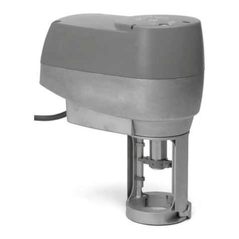
HS5 Series Door Handle Actuator
•The door handle actuator can be used with the HS5D-Z (metal
head), and HS5E-L/HS5E-KL/HS5L-L (rear unlocking button)
only. Do not use with HS5D plastic head or HS5E/HS5E-K rear
unlocking button models.
•When using the door handle actuator in the safety-related part of the
system, make sure of proper operation while observing the safety
standards and regulations of the relevant country or region where
the actual machine/system is used. Also, perform a risk assessment
before operation.
•Read the instruction sheet of interlock switch before installing the
door handle actuator.
•Install the switch cover unit and handle unit on the outside of the
door. Do not install them inside the door, otherwise the door cannot
be opened or closed by the operator, affecting the operation and
causing danger to the operator.
•Install the door handle actuator in the direction as
shown on the right, so that the cable faces downward.
Do not install in any other direction, otherwise
malfunction will be caused.
•Do not modify or disassemble the door handle
actuator.
Padlocking
•When padlocking the HS9Z-DH5, lift the knob
on the front of the HS9Z-DH5. A tab will appear.
Install padlock(s) or a hasp on the tab.
•Make sure that the total load by the padlocks
and hasp does not exceed 30N. Otherwise the
door handle actuator will become deformed or
damaged.
•The applicable shackle diameter of padlock is ø6.0 to 7.5 mm.
Manual Unlocking
•When using the HS5E-L/HS5L-
L interlock switch, attach the
manual unlock label on the front of
the switch cover unit.
•For manual unlocking, refer to the
specications for the HS5E-L/
HS5L-L rear unlocking button
model.
Handle Operation
•Push the handle, and turn the handle to insert the actuator.
Note: Do not force to turn the handle without pushing in the handle, otherwise
damage will occur.
•Do not close the door when the actuator is in the locked status,
otherwise the actuator will hit the door, resulting in deformation or
damage.
•When turning the handle, make sure that your hands or ngers are
not caught by the door.
Installation
•Check wether the following parts are included.
Unit Part Quantity
Switch Cover Unit
HS9Z-DH5C
Mounting Bracket 1
Switch Cover 1
Blind Cap 1
Screw A *1
Screw B *2
Screw C 4
Seal 1
Handle Unit
HS9Z-DH5RH
HS9Z-DH5LH
HS9Z-DH5RHN
HS9Z-DH5LHN
Actuator Cover 1
Front Handle (black) 1
Rear handle (gunmetal color) 1
Rear handle Shaft 1
Rear handle Plate 1
Rear handle Base 1
Screw D *2
Screw E 2
HS5D Installation Kit
HS9Z-DH5B
Mounting Plate 2
Spacer 1
*Screws A and B are loosely attached to the switch cover.
Screws D are loosely attached to the handles.
Installing the Switch Cover Unit (HS9Z-DH5C)
1. Remove one Screw A and two
Screws B from the switch cover
and remove the switch cover from
the mounting bracket.
2. HS5E-L/HS5E-KL/HS5L-L Interlock Switches
Using four Screws C, install the interlock switch on the mounting
bracket (panel thickness 3 mm or less). When installing on a
mounting panel (X) of 20 ≤ X ≤ 50 mm, install the connecting rod
onto the push rod and press the pin into the hole in the push rod as
described in the “Installing the Rear Unlocking Button Kit” on E-071,
before installing the switch on the mounting bracket.
Screw C
HS5E-44L
Screw C
HS5L-L
Interlock Switch
[HS5D-Z Interlock Switch]
Install the interlock switch using
the HS5D Installation Kit
(HS9Z-DH5B) and two Screws C.
3. Plug the unused actuator entry slot
using the blind cap. To do so, attach
the tab on one end to the switch cover,
and bending the blind cap, attach the
other end on the switch cover.
4. Install the switch cover on the mounting
plate using one Screw A and two
Screws B.
Padlock Knob
Normal Status Unlocked Status
LOCK UNLOCK
LOCK UNLOCK
LOCK
UNLOCK
Label
Push the
handle
Turn the handle
Bracket
Screw A
Screws C
Spacers
HS5D-Z
Interlock Switch Mounting Plate
Inside
pOutside
Switch
Blind Cap
Screws
Instructions


