6
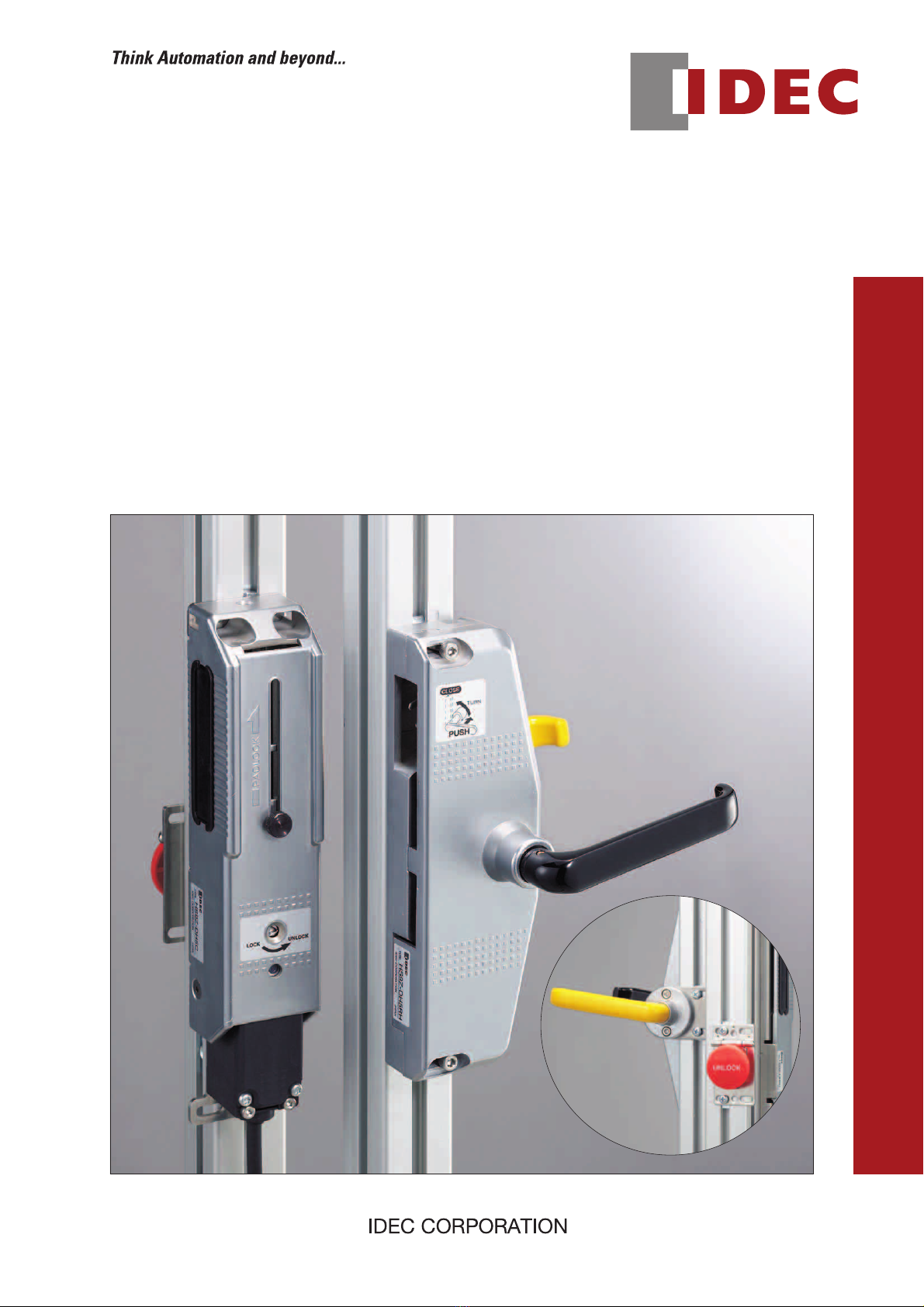
Easy and secure operation.
Rattling doors can be locked smoothly and securely.•
A door can be locked with an actuator by pushing and•
turning the handle.
Padlock tab is provided to ensure operator safety.•
Interlock switch with or without solenoid lock can be•
installed.
LED shows solenoid status•
(when using HS5E-∗44L∗∗-G).
HS5B/HS5E Door Handle Actuator
Specifications
Applicable Interlock
Switch
HS5B Metal Head Interlock Switch (Note 1)
HS5E Rear Unlocking Button Type Interlock
Switch with Solenoid (Note 2)
Operating Temperature –25 to +70°C (no freezing)
Mechanical Durability 100,000 operations minimum
Applicable Shackle
Diameter of Padlock ø6 to 7.5 mm
Withstand Load of
Padlock Tab 30N maximum
Handle Operation Angle 77° (removed position ↔ inserted position)
Weight
HS9Z-DH5LH/RH: 1000g
HS9Z-DH5C: 900g
HS9Z-DH5B: 30g
Note 1: HS5B-∗∗ZB, HS5B-∗∗ZBM
Note 2: HS5E-∗44L∗∗-G
Interlock switch is not supplied with the actuator and must be ordered separately.
•
For the specifications of interlock switches, see Cat No. EP1199-0.
•
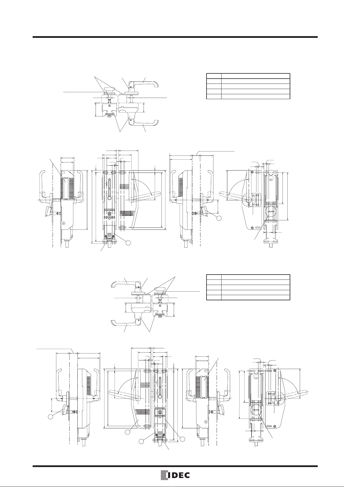
Types
Description Ordering Type No. Remarks
Handle Unit For right-hand door HS9Z-DH5RH Choose according to the required opening side.
For left-hand door HS9Z-DH5LH
Switch Cover Unit HS9Z-DH5C Used for installing the interlock switch inside.
HS5B Installation Kit HS9Z-DH5B Contains a mounting plate and two spacers.
Rear Unlocking Button Kit (Note 1)
HS9Z-FL53 Contains a button with base
plate and a connecting rod
Mounting panel thickness (X): 20 ≤X ≤30 mm
(Note 2)
HS9Z-FL54 Mounting panel thickness (X): 30 < X ≤40 mm
(Note 2)
Note 1: Use the kit in combination with the HS5E-∗44L∗∗-G rear unlocking button type interlock switch.
Note 2: Mounting panel is a frame or a panel.
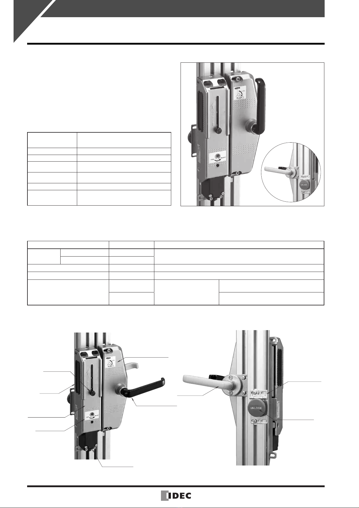
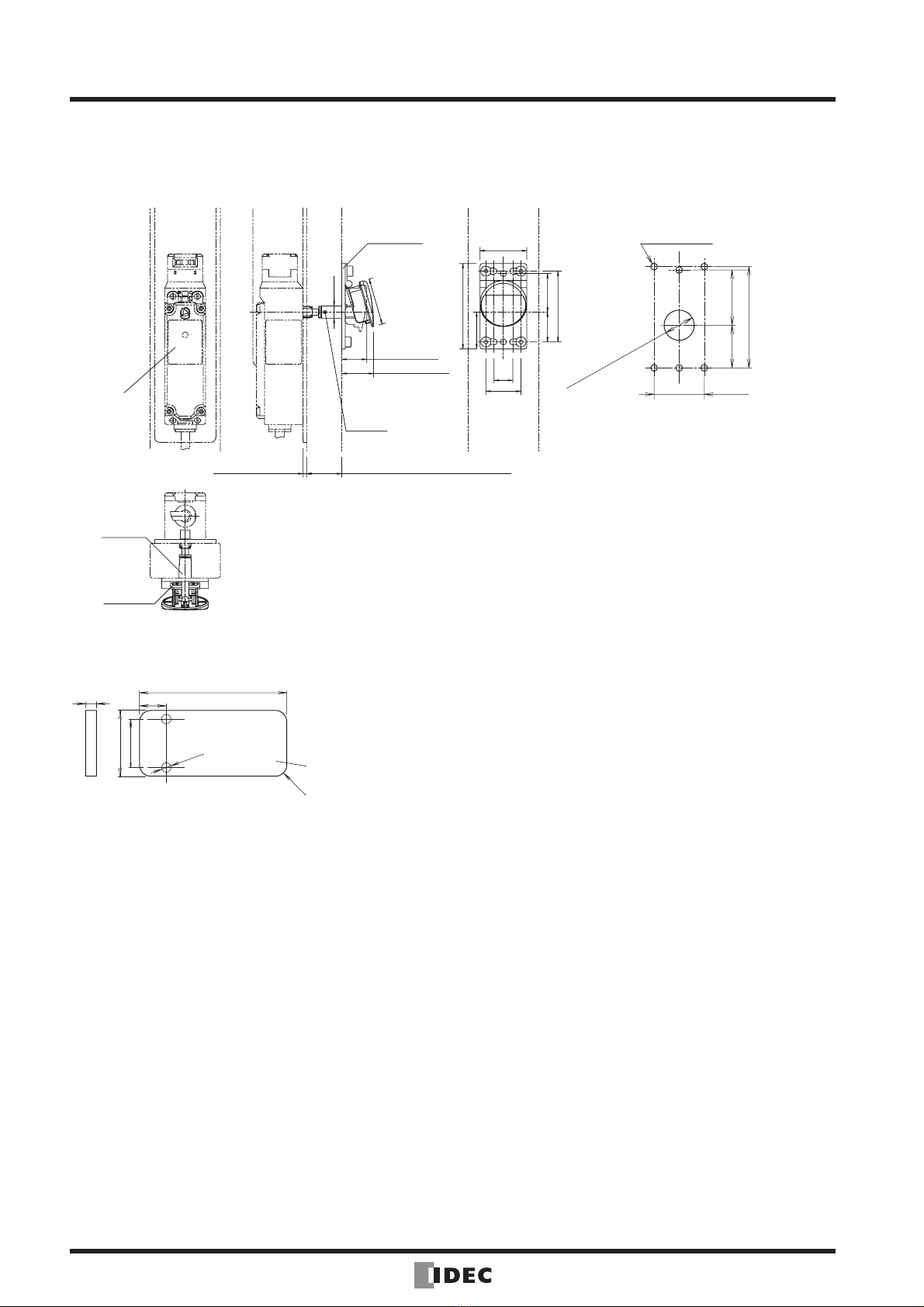
Parts Description
Rear Handle
(yellow)
Rear Unlocking
Button Kit
Rear Unlocking
Button
Padlock Knob
Blind Cap
Handle Unit
(for right-hand door)
Manual Unlock
Label
Interlock Switch
Front Handle (black)
Switch Cover Unit
Front View Rear View