2
No. Description Figure Q'ty No. Description Figure Q'ty
1
M-NET board
(with insulation
sheets and
supports)
17Lead wire
(5 wires) 1
2
Plate
(For mounting
M-NET board)
18Lead wire
(3 wires) 1
3Screw (M4×8) 29Lead wire
(2 wires) 1
4Terminal block
(M-NET) 10
Ground wire
and screw
(M4×8)
1
each
5Terminal screw
(M3×20) 11Fastener 2
6Label 1
length: 300mm (12 inch)
length: 280mm (11 inch)
length: 280mm (11 inch)
PAC-SJ96MA-E
INSTALLATION MANUAL FOR A-M CONVERTER
BH79N063H04
1
3 4
1.Parts List 2. Switch setting
SAFETY PRECAUTIONS
After installation, make test operation and confirm that it works properly, and explain the safety precautions, operation method, and
maintenance to your customers.
Tell your customers to keep this installation manual together with operation manual with them, and when they give or sell this machine to other
person put this installation manual and operation manual with it.
Before starting installation, read the "Safety Precautions" described below.
The following precautions must be observed as it describes the serious matters for safety.
The safety precautions are described with the degree of danger.
WARNING
WARNING
CAUTION
When you handle wrong, it can lead to death or serious injury.
When you handle wrong, it can lead to injury or damage to building and furniture.
The installation must be done by dealer or qualified person.
If the customers do the installation by themselves and it is not
perfectly installed it can cause water leak, electric shock, or fire.
The installation must be done in accordance with this manual.
If the installation is not perfectly done, it can cause water leak,
electric shock, or fire.
Turn the power on 12 hours or more before operation.
If you start operation as soon as the power on, it can cause failure.
Never turn the power off during season.
Never operate the machine without panel or guard off.
It can cause serious injury being caught by rotating part or burn or
electric shock by high voltage part.
Never operate the machine without air filter off.
It can cause failure by dust.
Never operate the switches with your hand wet.
It can cause electric shock.
Never touch refrigerant pipes while the machine running.
The refrigerant pipes becomes high and low temperature while the
machine running. If you touch the pipes by hand, it can cause
chilblain or burn.
Never turn the power off as soon as the machine stops.
Wait for 5 minutes or more. It can cause water leak or failure.
Install a circuit breaker depending upon the location.
Without a circuit breaker, it can cause electric shock.
Use standard wires which meet current capacity.
Otherwise, it can cause short-circuit, heat, or fire.
Put ground wire.
Never ground to gas pipe, water pipe, lightning conductor, or
telephone ground wire.
Faulty ground can cause electric shock.
Wires must not have tension.
It can cause snipping, heat, or fire.
Never try any modification.
For repair, ask your dealer.
If the machine is not modified or repaired completely, it can cause
water leak, electric shock, or fire.
The wiring must be securely done by using proper cable. The wires
should be connected to the terminals not to have external force of
the cable.
Faulty connections can cause heat or fire.
The terminal cover (panel) of the unit must be installed securely.
Faulty installation can cause fire or electric shock by dust or water.
The electric installation must be done by qualified person in
accordance with this installation manual. Use the separate circuit
only for this machine and use rated voltage and circuit breaker.
If the electric circuit power is not sufficient or the wiring is not
properly done, it can cause electric shock or fire.
Never move or reinstall the machine by the customers.
If the installation is not perfectly done, it can cause water leak,
electric shock, or fire. Ask your dealer or qualified person.
Before electric wiring
CAUTION
Before test operation
CAUTION
For models in which this component is used, see the separate sheet.
Centralized
controller
L1 L2
L3
Power supply
unit
M-NET transmission line
(Centralized control line)
M-NET transmission line
(Indoor control line)
A transmission line
MA remote controller line
Maximum power feeding length for
the centralized control line:
L1 [200 m (656 ft)
L2 + L3 [200 m (656 ft)
Indoor unit Indoor unit
Indoor unit Indoor unit
ME
controller
MA
controller
M-NET
Outdoor
unit
Mr. SLIM
Outdoor
unit
M-NET
Adapter
Indoor unit
Bad example (Multiple ground of shielded wire)
(1) Ground wire connection
(2) Length of M-NET transmission line
Centralized
controller
Power
supply unit
Power
supply unit
Power
supply unit
Outdoor
unit (*1)
Outdoor
unit (*1)
M-NET transmit wire NO NO NO
Centralized
controller
Outdoor
unit (*1)
Outdoor
unit (*1)
M-NET transmit wire OK
Centralized
controller
Outdoor
unit (*1)
Outdoor
unit (*1)
M-NET transmit wire OK (*2)
Good example (One spot ground of shielded wire)
Good example (One spot ground of shielded wire)
(*1) Refer to the appendix List of Models to check the applicable models.
Note: If the shield and earth are grounded in two or more locations, electrical circuit is generated through them, and a
potential difference is created because of the impedance difference between or among the ground locations.
This may cause noise in the shield. Ground at only one point, then no circuit is created and no noise gets in.
(*2)
Attention for M-NET connection
Pay attention to the next points for wiring of shielded wires.
CAUTION
The shielded wires of M-NET transmission should be
connected with the ground wire at any only one place
of the unit to be connected.
,WFDQFDXVHWKHWUDQVPLVVLRQHUURUGXHWRQRLVH
Outdoor unit digital LED display reads "Ed" "A7" error.
Centralized controller reads “0403” “6607” error.
CAUTION
The shielded wires of M-NET transmission should be
used below the maximum line length.
,WFDQFDXVHWKHWUDQVPLVVLRQHUURU
Outdoor unit digital LED display reads "Ed" "A7" error.
Centralized controller reads "0403" "6607" error.
M-NET
terminal block
Ground wire
(accessory)
Transmit
wire Shielded
wire
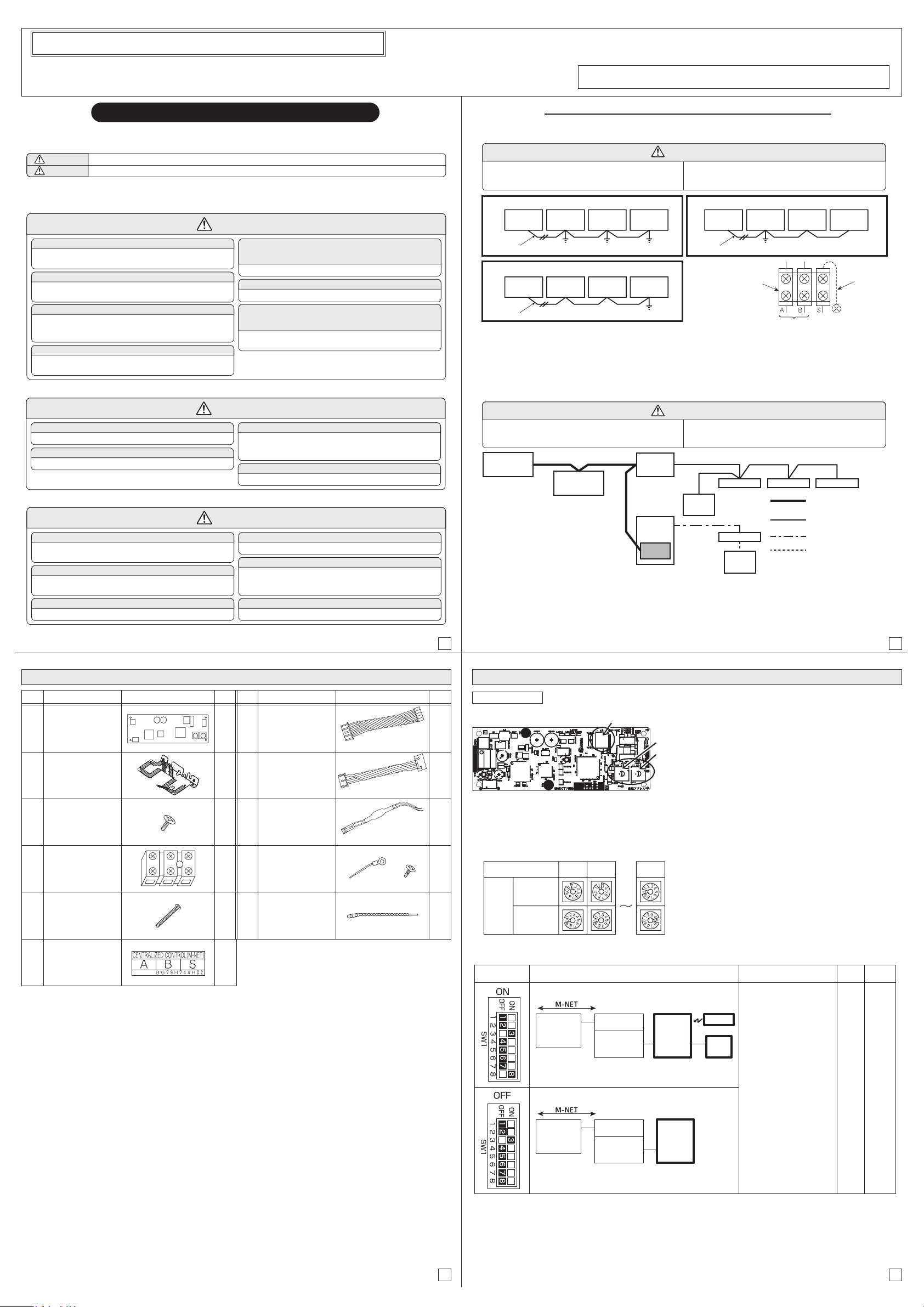
(1) M-NET address setting
The setting should be done by rotary switches SW11 and SW12 on M-NET board. (Factory settings are all Zero)
Make sure to set M-NET address within the range of 01 to 50.
When installing two or more outdoor units, do not use the same number more than once for M-NET address.
(2) Switch 1-8 setting
M-NET address No.
Switch
setting
SW 11
(Ones digit)
SW 12
(Tens digit)
12 50
Function details Initial
setting
Effective
timing
SW1-8
Selection Function
Turn the switch ON when MA remote controller or wireless
remote controller is connected to indoor unit.
Turn the switch OFF when MA remote controller or wireless
remote controller is NOT connected to indoor unit.
Note: SW1í3 is always ON
M-NET board
SW1-8 ON
Outdoor
unit
M-NET board
SW1-8 OFF
Outdoor
unit
Indoor
unit
RC
OR
MA
MA: MA remote controller
RC: Wireless remote controller
Indoor
unit
Centralized
controller
Centralized
controller
<FUNCTION>
Set the connection of MA-
remote controller or
wireless remote controller
to the indoor unit.
ON : exist (initial setting)
OFF : not exist
<NOTE>
In case of switch is ON,
transmission error between
M-NET board and
centralized controllers does
not be detected, and
M-NET board operates
continuously.
ON
When
power
supply
ON
SW12
SW11
SW1
M-NET board
Before installation
Set switch on M-NET board in advance before installing on the electrical parts box.
<Example>
(*2) In case that the outdoor unit is grounded, connect the ground wire supplied as accessory to the S terminal (secondary)
of M-NET terminal block and M-NET ground terminal inside of electrical parts box with using screws supplied.
(3) Using dual set point
1. To activate dual set point, make sure that all units and controllers in one group have dual set point function.
2. To change the temperature display setting of existing group from single to dual set point, make sure to restart the
whole system related.
3. When ME remote controller is included in same group in the case of 2, make sure to initialize* ME remote controller
before use.
(*Refer to the ME remote controller installation manual. <Service Menu.>)


 User manual")


