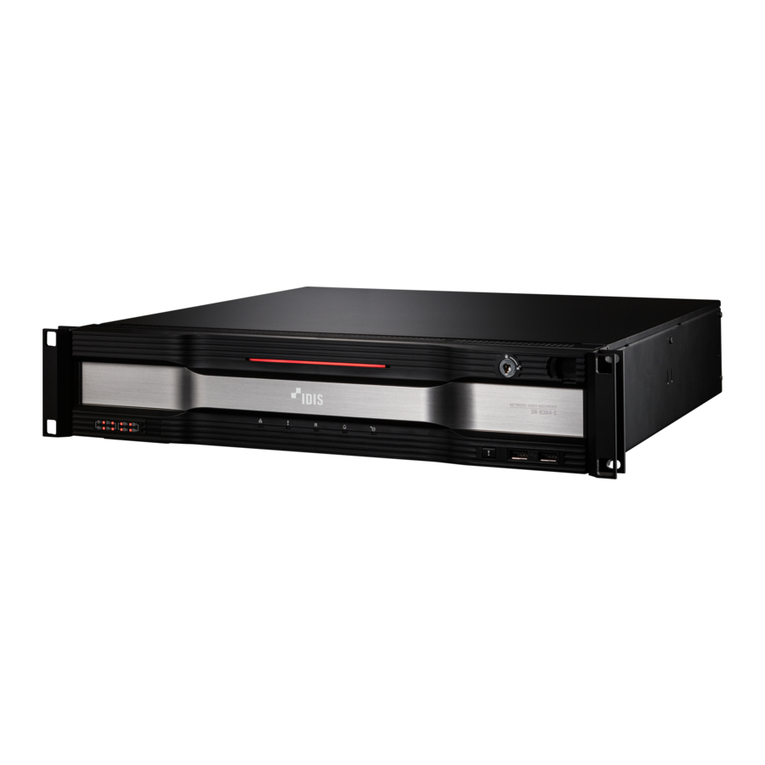
Idis IR-1100 User manual

© IDIS Co., Ltd. All rights reserved. IDIS and identifying product names and numbers herein are registered trademarks of IDIS Co., Ltd.
All non-IDIS brands and product names are trademarks of their respective companies.
Product appearance, build status and/or specifications are subject to change without notice.
IR-1100
Quick Guide
Version 1.0.0

2
Quick Guide
IR-1100
Version 1.0.0
Before reading this manual
This manual contains basic instructions on installing and using IR-1100 Network Video Recorder.
Users who are using this product for the first time, as well as users with experience using comparable
products, must read this manual carefully before use and heed to the warnings and precautions contained
herein while using the product. Safety warnings and precautions contained in this manual are intended to
promote proper use of the product and thereby prevent accidents and property damage and must be
followed at all times.
Once you have read this manual, keep it at an easily accessible location for future reference.
• The manufacturer will not be held responsible for any product damage resulting from the use of
unauthorized parts and accessories or from the user's failure to comply with the instructions contained in this
manual.
• It is recommended that first-time users of IDIS IR-series Network Video Recorder and individuals who are
not familiar with its use seek technical assistance from their retailer regarding product installation and use.
• If you need to disassemble the product for functionality expansion or repair purposes, you must contact
your retailer and seek professional assistance.
Safety, Environmental, and Regulatory Information
Refer to the Safety, Environmental, and Regulatory Information document included in the product
package.
Copyright
ⓒ2020 IDIS Co., Ltd.
IDIS Co., Ltd. reserves all rights concerning this manual.
Use or duplication of this manual in part or whole without the prior consent of IDIS Co., Ltd. is strictly
prohibited.
Contents of this manual are subject to change without prior notice..
Registered Trademarks
IDIS is a registered trademark of IDIS Co., Ltd.
Other company and product names are registered trademarks of their respective owners.

3
Version 1.0.0
Quick Guide
IR-1100
Table of Contents
1Introduction............................................................................................................................................ 4
2Accessories ........................................................................................................................................... 5
3Overview................................................................................................................................................. 6
3.1 Dimension................................................................................................................................................ 6
3.2 Front Panel.............................................................................................................................................. 6
3.3 Rear Panel..............................................................................................................................................11
3.4 Front Bezel............................................................................................................................................ 13
4Getting Started..................................................................................................................................... 14
4.1 Setting Windows OS.............................................................................................................................. 14
4.2 Setting Built-in SSD Storages ............................................................................................................... 16
4.3 Setting Recording Drives....................................................................................................................... 17
4.4 Installing IDIS Solution Suite................................................................................................................. 33
4.5 Teaming Network Interface Controller(NIC) .......................................................................................... 34
5Licenses and Service Codes.............................................................................................................. 40
5.1 Windows OS License ............................................................................................................................ 40
5.2 IDIS Solution Suite License................................................................................................................... 41
5.3 Service Tag or Express Service Code................................................................................................... 41
6Specification ........................................................................................................................................ 42
7Warranty............................................................................................................................................... 44

4
Version 1.0.0
Quick Guide
IR-1100
1 Introduction
This is a video recorder that supports surveillance, recording, and playback of video from network cameras
or video encoders.
This NVR (Network Video Recorder) unit offers the following features:
Tested and validated with IDIS Solution Suite up to 256 Full HD H.264/H.265 IP cameras
Supports up to 256 Full HD cameras in real-time for enterprise-level surveillance systems
1,024Mbps (128MBps) maximum recording bandwidth per server
Redundancy of power for mission-critical reliability
Complete compatibility with IDIS components: IP cameras, analog DVR, DirectCX TVR, DirectIP NVR,
and encoders
Equipped with RAID 5, RAID 6 recording, Hot swappable
2U rack mount chassis with sliding rails and cable management arm for ease of serviceability
Supports H.264, H.265 compression, and Intelligent Codec
Supports Onvif Profile S, Axis, Panasonic, etc.

5
Version 1.0.0
Quick Guide
IR-1100
2 Accessories
Upon unpackaging the product, check the contents inside to ensure that all the following accessories are
included.
No.
Component
Quantity
1
IR-1100 Main Body
1
2
Front Chassis & Lock Key
1
3
Safety, Environmental, and Regulatory Information Manual
1
4
Power Code (AType- Deskside)
2
5
Power Jumper Code (10A,4M,C13/C14)
2
6
Rack Mounting Bracket
1
7
Rack Installation Instructions Manual
1
8
Cable Strap
2 (1 pack)
1
3
6
4
5
7
8
2

6
Version 1.0.0
Quick Guide
IR-1100
3 Overview
3.1 Dimension
X
Y
Z
482.0 mm (18.98 inch)
86.8 mm (3.42 inch)
717.6 mm (28.25 inch)
3.2 Front Panel
1 2 3
Item
Component
Description
1
Left control panel
Contains system health and system ID, status LED and optional
iDRAC Quick Sync 2 (wireless).
2
Drive slots
Enable you to install up to 8 drives that are supported on your system.
3
Right control panel
Contains the power button, VGA port, iDRAC Direct micro USB port,
and two USB 2.0 ports.

7
Version 1.0.0
Quick Guide
IR-1100
Left control panel3.2.1
Item
Indicator
Icon
Description
1
Status LED
N/A
Indicate the status of the system.
The indicators display solid amber if any error occurs.
For more information, see Status LED indicators.
2
System health
and ID
Indicates the system health.
For more information, see System Health and System ID
indicator.
3
iDRAC Quick
Sync 2 wireless
indicator
Indicates if the iDRAC Quick Sync 2 wireless option is activated.
The Quick Sync 2 feature allows management of the system
using mobile devices. This feature aggregates
hardware/firmware inventory and various system level
diagnostic/error information that can be used in troubleshooting
the system.
For more information, see iDRAC Quick Sync 2 indicator.
(1) Status LED Indicators
Icon
Indicator
Condition
Corrective Action
Drive
The indicator turns solid
amber if there is a drive error.
Check the System Event Log to determine
if the drive has an error.
If the drives are configured in a RAID
array, restart the system, and enter the
host adapter configuration utility program.
Temperature
The indicator turns solid
amber if the system
experiences a thermal error.
Ensure that none of the following conditions
exist:
A cooling fan has been removed or has
failed.
System cover, air shroud, memory module
blank, or back filler bracket is removed.
Ambient temperature is too high.
External airflow is obstructed.
Electrical
The indicator turns solid
amber if the system
experiences an electrical
error (for example, voltage
out of range, or a failed
power supply unit (PSU) or
voltage regulator).
Check the System Event Log or system
messages for the specific issue. If it is due to a
problem with the PSU, check the LED on the
PSU. Reseat the PSU.
Memory
The indicator turns solid
amber if a memory error
occurs.
Check the System Event Log or system
messages for the location of the failed
memory. Reseat the memory module.

8
Version 1.0.0
Quick Guide
IR-1100
PCIe
The indicator turns solid
amber if a PCIe card
experiences an error.
Restart the system. Update any required
drivers for the PCIe card. Reinstall the card.
(2) System Health and System ID indicator
Indicator code
Condition
Solid blue
Indicates that the system is turned on, system is healthy, and system ID mode is not
active. Press the system health and system ID button to switch to system ID mode.
Blinking blue
Indicates that the system ID mode is active. Press the system health and system ID
button to switch to system health mode.
Solid amber
Indicates that the system is in fail-safe mode.
Blinking amber
Indicates that the system is experiencing a fault. Check the System Event Log for
specific error messages.
(3) iDRAC Quick Sync 2 indicator
Indicator code
Condition
Corrective Action
Off (default state)
Indicates that the iDRAC Quick
Sync 2 feature is turned off.
Press the iDRAC Quick Sync 2 button to turn
on the iDRAC Quick Sync 2 feature.
If the LED fails to turn on, reseat the left
control panel flex cable and check.
Solid white
Indicates that iDRAC Quick
Sync 2 is ready to communicate.
Press the iDRAC Quick Sync 2 button to turn
off.
If the LED fails to turn off, restart the system.
Blinks white
rapidly
Indicates data transfer activity.
If the indicator continues to blink indefinitely,
contact the installer or seller.
Blinks white
slowly
Indicates that firmware update is
in progress.
If the indicator continues to blink indefinitely,
contact the installer or seller.
Blinks white five
times rapidly and
then turns off
Indicates that the iDRAC Quick
Sync 2 feature is disabled.
Check if iDRAC Quick Sync 2 feature is
configured to be disabled by iDRAC.
Solid amber
Indicates that the system is in
fail-safe mode.
Restart the system.
Blinking amber
Indicates that the iDRAC Quick
Sync 2 hardware is not
responding properly.
Restart the system.

9
Version 1.0.0
Quick Guide
IR-1100
Drive slots3.2.2
Each drive carrier has an activity LED indicator and a status LED indicator.
1 2 3 4
Item
Component
Icon
Description
1
Drive status indicator
Indicates the power condition of the drive.
2
Drive activity indicator
Indicates whether the hard drive is currently in use or not.
3
Drive release button
N/A
Press the button to open the drive carrier release handle to
remove or replace the drive.
4
Drive information tag
N/A
Shows the drive information such as capacity, drive type,
rpm and so on.
(1) Drive status indicator code
Indicator code
Condition
Flashes green twice per second
Identifying drive or preparing for removal.
Off
Drive ready for removal.
NOTE: The drive status indicator remains off until all
drives are initialized after the system is turned on.
Drives are not ready for removal during this time.
Flashes green, amber, and then turns off
Predicted drive failure.
Flashes amber four times per second
Drive failed.
Flashes green slowly
Drive rebuilding.
Solid green
Drive online.
Flashes green for three seconds, amber for three
seconds, and then turns off after six seconds
Rebuild stopped.
NOTE: If the drive is in the Advanced Host Controller Interface (AHCI) mode, the status LED indicator does
not turn on.

10
Version 1.0.0
Quick Guide
IR-1100
Right control panel3.2.3
Item
Indicator
Icon
Description
1
Power button
Indicates if the system is turned on or off. Press the power
button to manually turn on or off the system.
2
USB port (2)
The USB ports are 4-pin, 2.0-compliant. These ports enable
you to connect USB devices to the system.
3
iDRAC Direct port
Indicates if the iDRAC Quick Sync 2 wireless option is
activated. The Quick Sync 2 feature allows management of
the system using mobile devices. This feature aggregates
hardware/firmware inventory and various system level
diagnostic/error information that can be used in
troubleshooting the system.
4
iDRAC Direct LED
N/A
The iDRAC Direct LED indicator lights up to indicate that
the iDRAC Direct port is connected.
For more information, see iDRAC Direct LED indicator.
5
VGA port
Enables you to connect a display device to the system.
(1) iDRAC Direct LED indicator
Indicator code
Condition
Solid green for two seconds
Indicates that the laptop or tablet is connected.
Flashing green (on for two seconds and
off for two seconds)
Indicates that the laptop or tablet connected is recognized.
Turns off
Indicates that the laptop or tablet is unplugged.

11
Version 1.0.0
Quick Guide
IR-1100
3.3 Rear Panel
1 2 3
4 5 6 7 8 9 10
Item
Component
Icon
Description
1
Full-height PCIe
expansion card slot
N/A
The PCIe expansion card slot (riser 1) connects up to three
full-height PCIe expansion cards to the system.
2
Half-height PCIe
expansion card slot
N/A
The PCIe expansion card slot (riser 2) connects one half-
height PCIe expansion cards to the system.
3
Rear handle
N/A
The rear handle can be removed to enable any external
cabling of PCIe cards that are installed in the PCIe expansion
card slot
4
System identification
button
The System Identification (ID) button is available on the front
and back of the systems. Press the button to identify a system
in a rack by turning on the system ID button. You can also use
the system ID button to reset iDRAC and to access BIOS using
the step through mode.
5
iDRAC dedicated
port
Enables you to remotely access iDRAC.
6
Serial port
Enables you to connect a serial device to the system.
7
VGA port
Enables you to connect a display device to the system.
8
USB port
The USB ports are 9-pin and 3.0-compliant. These ports
enable you to connect USB devices to the system.
9
NIC port
The NIC ports that are integrated on the network daughter card
(NDC) provide network connectivity.
10
Power supply unit
N/A
Supplies power to the system.
(1) NIC indicator
Item
Component
Description
1
Link LED indicator
Indicates the speed of the connected network.
2
Activity LED indicator
Indicates if data is flowing through the NIC.
1 2

12
Version 1.0.0
Quick Guide
IR-1100
Indicator code
Condition
Link and activity indicators are off
The NIC is not connected to the network.
Link indicator is green and activity
indicator is blinking green
The NIC is connected to a valid network at its maximum port
speed and data is being sent or received.
(2) Power Supply Unit (PSU) indicator
Item
Component
Description
1
AC PSU status indicator
Shows whether power is present or if a power fault has occurred.
Indicator code
Condition
Green
A valid power source is connected to the PSU and the PSU is operational.
Blinking amber
Indicates a problem with the PSU.
Not illuminated
Power is not connected to the PSU.
Blinking green
When the firmware of the PSU is being updated, the PSU handle blinks green.
CAUTION: Do not disconnect the power cord or unplug the PSU when updating
firmware. If firmware update is interrupted, the PSUs do not function.
Blinking green and
turns off
When hot-plugging a PSU, the PSU handle blinks green five times at a rate of 4 Hz
and turns off. This indicates a PSU mismatch with respect to efficiency, feature set,
health status, or supported voltage.
CAUTION: If two PSUs are installed, both the PSUs must have the same type of
label; for example, Extended Power Performance (EPP) label. Mixing PSUs from
previous generations of PowerEdge servers is not supported, even if the PSUs
have the same power rating. This results in a PSU mismatch condition or failure to
turn the system on.
CAUTION: When correcting a PSU mismatch, replace only the PSU with the
blinking indicator. Swapping the PSU to make a matched pair can result in an error
condition and unexpected system shutdown. To change from a high output
configuration to a low output configuration or vice versa, you must turn off the
system.
CAUTION: AC PSUs support both 240 V and 120 V input voltages with the
exception of Titanium PSUs, which support only 240 V. When two identical PSUs
receive different input voltages, they can output different wattages, and trigger a
mismatch.
CAUTION: If two PSUs are used, they must be of the same type and have the
same maximum output power.
1

13
Version 1.0.0
Quick Guide
IR-1100
3.4 Front Bezel
A key is located at the backside of the front bezel. You can secure recording storages by locking the lock on
the front side of the bezel.

14
Version 1.0.0
Quick Guide
IR-1100
4 Getting Started
4.1 Setting Windows OS
Setting password4.1.1
Default login details for IR-1100 are as follows.
ID: Administrator
Password: P@ssw0rd
Log in with the login detail above, and make sure to change the password for security.
(1) Click ‘Windows Setup >Control Panel >User Accounts >Manage another account’.
(2) Select Administrator account, then select ‘Change the password’menu.
(3) Change password of Administrator account considering the following password rules.
- Be at least six characters in length
- Contain characters from three of the following four categories;
English uppercase letters (A through Z)
English lowercase letters (a through z)
Base 10 digit (0 through 9)
Non-alphabetic characters ( !,@,#,$,%&,*)

15
Version 1.0.0
Quick Guide
IR-1100
NOTE. It is recommended to create a password reset disk by clicking ‘Windows Setup >Control Panel >
User Accounts >Create a password reset disk’to reset a password when you forget the password of
administrator or user account. A USB memory device or CD/DVD is needed to create a password reset disk.
Activating Windows OS license4.1.2
Windows on the IR-1100 is basically activated when it is dispatched. Windows OS must be activated in the
following picture. If your Windows OS is not activated, please refer to ‘Checking Windows OS Key’and
activate your Windows OS with your Windows OS Key.

16
Version 1.0.0
Quick Guide
IR-1100
4.2 Setting Built-in SSD Storages
Two 240GB SSDs are located inside of IR-1100. Typically, the SSDs are on RAID 1 level which appears to
be a single drive. Windows OS is installed on this drive and IDIS Solution Suite installation package is
located on the same drive as well. This drive is used for software installation.
Checking the SSD status procedure is as follows.
On the Windows OS > Device Manager, check if 240GB SSD is recognized.
If you check ‘Windows Setup > File Explorer > Device and drives’, SDDs are available as a single Logical
Disk (C:).
You can also see SDDs are configured as a single Logical Disk at ‘Windows Setup > Disk Management’Disk.

17
Version 1.0.0
Quick Guide
IR-1100
4.3 Setting Recording Drives
Installing Recording Drives4.3.1
Maximum 8 of 3.5”HDD can be attached to the Drive slots of System..
Drives for recording purposes can be installed by the procedure below.
(1) Insert the 3.5 inch drive adapter into the drive carrier with the connector end of the drive toward the back
of the drive carrier.
(2) Align the drive’s screw holes with the holes on the drive carrier.
(3) Install the screws to secure the drive to the drive carrier.
1 3 5 7
2 4 6 8

18
Version 1.0.0
Quick Guide
IR-1100
Configuring RAID4.3.2
Configuring RAID for recording HDD can be done by entering System Setup menu from the boot up process.
(1) Press F2 while system is booting up, then select ‘Entering System Setup’from the BIOS configuration
screen.
(2) Select ‘System Setup Main Menu >Device Settings’.

19
Version 1.0.0
Quick Guide
IR-1100
(3) Select ‘Integrated RAID Controller 1:Dell <PERC H740 Mini> Configuration Utility’.
(4) Select ‘Dashboard View >Main Menu’.

20
Version 1.0.0
Quick Guide
IR-1100
(5) Select ‘Configuration Management >Create Virtual Disk’.
(6) Configure the main elements from ‘Create Virtual Disk’menu.
- Select RAID Type.
Table of contents
Other Idis Network Hardware manuals
Idis
Idis DR-6316PS User manual
Idis
Idis DR-6232H User manual

Idis
Idis DR-8516 User manual

Idis
Idis DR-2304A User manual

Idis
Idis DR-6316PS-S User manual

Idis
Idis DR-1500 Series User manual
Idis
Idis DR-2404P User manual
Idis
Idis DR-4516P User manual
Idis
Idis DR-2100P Series User manual
Idis
Idis DR-8416 User manual
Idis
Idis DR-2204P User manual

Idis
Idis DR-6100 Series User manual

Idis
Idis DR-2508P User manual
Idis
Idis DirectIP DR-1304P User manual
Idis
Idis DR-2304P User manual

Idis
Idis DR-6516P-A User manual

Idis
Idis DR-2516P User manual
Idis
Idis DirectIP DR-6516P User manual
Idis
Idis DR-6232H User manual

Idis
Idis DirectIP DR-6532P User manual


