manuals.online logo
Brands
  1. Home
  2. •
  3. Brands
  4. •
  5. ADTRAN
  6. •
  7. Network Hardware
  8. •
  9. ADTRAN TRACER 4x06 Reference manual

ADTRAN TRACER 4x06 Reference manual

612804106L2-18A © 2004 ADTRAN, Inc. 1
Converting the Frequency Plan of a TRACER 4x06(L2) System
Introduction
TRACER 4x06 systems are shipped from the factory with the frequency plan programmed as Plan A or
Plan B. Each wireless link must contain a Plan A radio on one end and a Plan B on the other. A frequency
plan conversion may be performed in the field, but should only be attempted if absolutely necessary and
must always be performed by qualified personnel. This document outlines the procedure for changing the
frequency plan of a List 2 (L2) TRACER 4x06 system (TRACER 4106 - P/N 12804106L2A/B or
TRACER 4206 - P/N 12804206L2A/B).
Prerequisite Procedures
The current frequency plan configuration is listed on a label located on the rear panel of the unit (near the
Antenna connector). Record the current configuration before beginning this procedure.
Tools and Materials Required
• 5/16” Torque wrench (8 in-lbs)
• 3/16” nut driver
• Phillips-head screw driver
Disconnect all cables attached to the TRACER 4x06 system (including power, data,
terminal RS-232, etc.) before performing this procedure.
Do not attempt to perform the conversion without the proper tools (see list below). Using
improper tools will damage the unit.
Electronic equipment can be damaged by static electrical discharge. Before handling
equipment, put on an antistatic discharge wrist strap to prevent damage to components.
Place equipment in antistatic packing material when transporting or storing. When
working on equipment, always place it on an approved antistatic mat that is electrically
grounded.
TRACER 4x06(L2) Frequency Conversion Document
2 © 2004 ADTRAN, Inc. 612804106L2-18A
1. Remove the screws from the chassis cover using a Phillips-head screwdriver (see Figure 1).
Figure 1. Removing the Cover Screws (TRACER 4x06)
2. Remove the nuts on either side of the RS-232 connector (on the rear panel of the unit) using the 3/16”
nut driver (see Figure 2).
Figure 2. Removing the RS-232 Nuts
3. Carefully slide the cover toward the back of the unit until the front edge of the cover is disconnected
from the front of the unit. Lift the cover off and set aside.
Perform the steps below in the order listed.
Remove all connected mounting brackets before attempting to remove the unit cover.
TRACER 4x06(L2) Frequency Conversion Document
612804106L2-18A © 2004 ADTRAN, Inc. 3
4. Verify the current frequency plan configuration. To verify the plan, check the connections between the
J connectors (located on the board and labeled J1 and J2) and the Chan connectors (located on the
diplexer). The Chan connectors are labeled 2421 (Chan 1) and 2462 (Chan 2) for most TRACER 4106
systems and CH1 and CH2 for most TRACER 4206 systems. The following table outlines the
connections for Plan A and B.
Click to see a digital image of the J connectors or the Chan connectors.
5. Using the torque wrench, disconnect both cables from the Chan connectors on the diplexer. Do not
attempt to disconnect the J connectors (located on the board) as this will cause damage. Click here for
a digital picture of this step.
6. Carefully flex the cables to swap the connections. Be careful with the RF cables, making sure that the
minimum bend radius of the cable is greater than 0.75"; bends and loops smaller than a quarter will
cause the RF cable to break. Use the wiring guidelines in Figure 3 and Figure 4 on page 4 for help with
wire placement. Click here for a digital picture of this step.
Figure 3. TRACER 4106 Cable Routing Diagrams
TRACER 4x06
PLAN CHAN 1 CHAN 2
AJ2 J1
BJ1 J2
Allowing the RF cables to sit on the processor and radio boards (green) could cause
damage to the boards; keep the RF cables off the boards while re-routing them. Click here
for a digital picture of this mistake.
J2
J1
ANT
PLAN B
J1 CABLE OVER ANT CABLE
2421
2462
J2
J1
ANT
PLAN A
J2 CABLE UNDER J1 CABLE
2421
2462
TRACER 4x06(L2) Frequency Conversion Document
4 © 2004 ADTRAN, Inc. 612804106L2-18A
Figure 4. TRACER 4206 Cable Routing Diagrams
7. Use the torque wrench to reconnect the RF cables to the Chan connectors. Tighten the cables by
turning clockwise until you hear a click from the wrench. DO NOT overtighten connectors as this will
cause the RF cable to break. The TRACER 4x06 system will not operate properly with broken RF
cables.
8. Reinstall the cover and carefully tighten all screws.
9. Change label on back of the unit to reflect the Plan change.
J1 J2
CH2 CH1
PLAN B
J1 J2
CH2 CH1
PLAN A
>> BACK
>> BACK
>> BACK
>> BACK
>> BACK

Other ADTRAN Network Hardware manuals

ADTRAN DUAL Nx56/64 1200142L1# User manual

ADTRAN

ADTRAN DUAL Nx56/64 1200142L1# User manual

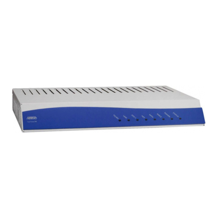
ADTRAN TRACER 4106 Plan User guide

ADTRAN

ADTRAN TRACER 4106 Plan User guide

ADTRAN 1200221L1 User manual

ADTRAN

ADTRAN 1200221L1 User manual

ADTRAN Total Access 1100F User manual

ADTRAN

ADTRAN Total Access 1100F User manual

ADTRAN DS3 NIU3 User manual

ADTRAN

ADTRAN DS3 NIU3 User manual

ADTRAN Total Access 3000 Manual

ADTRAN

ADTRAN Total Access 3000 Manual

ADTRAN HDSL4 User manual

ADTRAN

ADTRAN HDSL4 User manual

ADTRAN NetVanta 5660 User manual

ADTRAN

ADTRAN NetVanta 5660 User manual

ADTRAN NetVanta Series User manual

ADTRAN

ADTRAN NetVanta Series User manual

ADTRAN Quad T1 IMA Instruction Manual

ADTRAN

ADTRAN Quad T1 IMA Instruction Manual

ADTRAN 1200 Series User manual

ADTRAN

ADTRAN 1200 Series User manual

ADTRAN SDX 611 GPON SFU ONT User manual

ADTRAN

ADTRAN SDX 611 GPON SFU ONT User manual

ADTRAN SLC-5 U-BR1TE III Instruction Manual

ADTRAN

ADTRAN SLC-5 U-BR1TE III Instruction Manual

ADTRAN Total Access 300 Series User manual

ADTRAN

ADTRAN Total Access 300 Series User manual

ADTRAN DSU/CSU Product manual

ADTRAN

ADTRAN DSU/CSU Product manual

ADTRAN TRACER 4205 User manual

ADTRAN

ADTRAN TRACER 4205 User manual

ADTRAN DSU III TDM User manual

ADTRAN

ADTRAN DSU III TDM User manual

ADTRAN TOTAL ACCESS 1200 User manual

ADTRAN

ADTRAN TOTAL ACCESS 1200 User manual

ADTRAN 1203019L2 User manual

ADTRAN

ADTRAN 1203019L2 User manual

ADTRAN Total Access 3050 User manual

ADTRAN

ADTRAN Total Access 3050 User manual

ADTRAN NetVanta Serial Dial Backup Interface Module (DIM)... User manual
ADTRAN

ADTRAN NetVanta Serial Dial Backup Interface Module (DIM)... User manual

ADTRAN TSU LT User manual

ADTRAN

ADTRAN TSU LT User manual

ADTRAN Total Access 900 Series User manual

ADTRAN

ADTRAN Total Access 900 Series User manual

ADTRAN GPON TA352 User manual

ADTRAN

ADTRAN GPON TA352 User manual

Popular Network Hardware manuals by other brands

Trend Micro Cloud Edge 100 G2 quick start guide

Trend Micro

Trend Micro Cloud Edge 100 G2 quick start guide

FireBrick FB2700 user manual

FireBrick

FireBrick FB2700 user manual

Cabletron Systems WPIM T1 user guide

Cabletron Systems

Cabletron Systems WPIM T1 user guide

Hypercom IEN 500 Technical specifications

Hypercom

Hypercom IEN 500 Technical specifications

Philips Dynalite DDPB22RJ12 instruction manual

Philips

Philips Dynalite DDPB22RJ12 instruction manual

Adeunis RF COMFORT LwM2M user guide

Adeunis RF

Adeunis RF COMFORT LwM2M user guide

Devolo Giga Bridge manual

Devolo

Devolo Giga Bridge manual

Interlogix TruVision NVR 50 quick start guide

Interlogix

Interlogix TruVision NVR 50 quick start guide

D-Link DIR-615 - Wireless N Router Installation

D-Link

D-Link DIR-615 - Wireless N Router Installation

D-Link DNS-321 - Network Storage Enclosure Hard Drive... Quick install guide

D-Link

D-Link DNS-321 - Network Storage Enclosure Hard Drive... Quick install guide

Balluff Easy Tool-ID BSG TID-05-T30-00-005 Installation and operation

Balluff

Balluff Easy Tool-ID BSG TID-05-T30-00-005 Installation and operation

Cradlepoint COR IBR900 Series quick start guide

Cradlepoint

Cradlepoint COR IBR900 Series quick start guide

Dahua NVR41 series user manual

Dahua

Dahua NVR41 series user manual

UeeVii CPE452 user manual

UeeVii

UeeVii CPE452 user manual

Cisco AIR-BR1410A-A-K9 - Aironet 1410 Wireless... Deployment guide

Cisco

Cisco AIR-BR1410A-A-K9 - Aironet 1410 Wireless... Deployment guide

Foxconn RAID user guide

Foxconn

Foxconn RAID user guide

Unitech MR055 Specifications

Unitech

Unitech MR055 Specifications

Compaq 312134-B21 - Intel Pentium II Xeon Processor... White paper

Compaq

Compaq 312134-B21 - Intel Pentium II Xeon Processor... White paper

manuals.online logo
manuals.online logoBrands
  • About & Mission
  • Contact us
  • Privacy Policy
  • Terms and Conditions

Copyright 2025 Manuals.Online. All Rights Reserved.