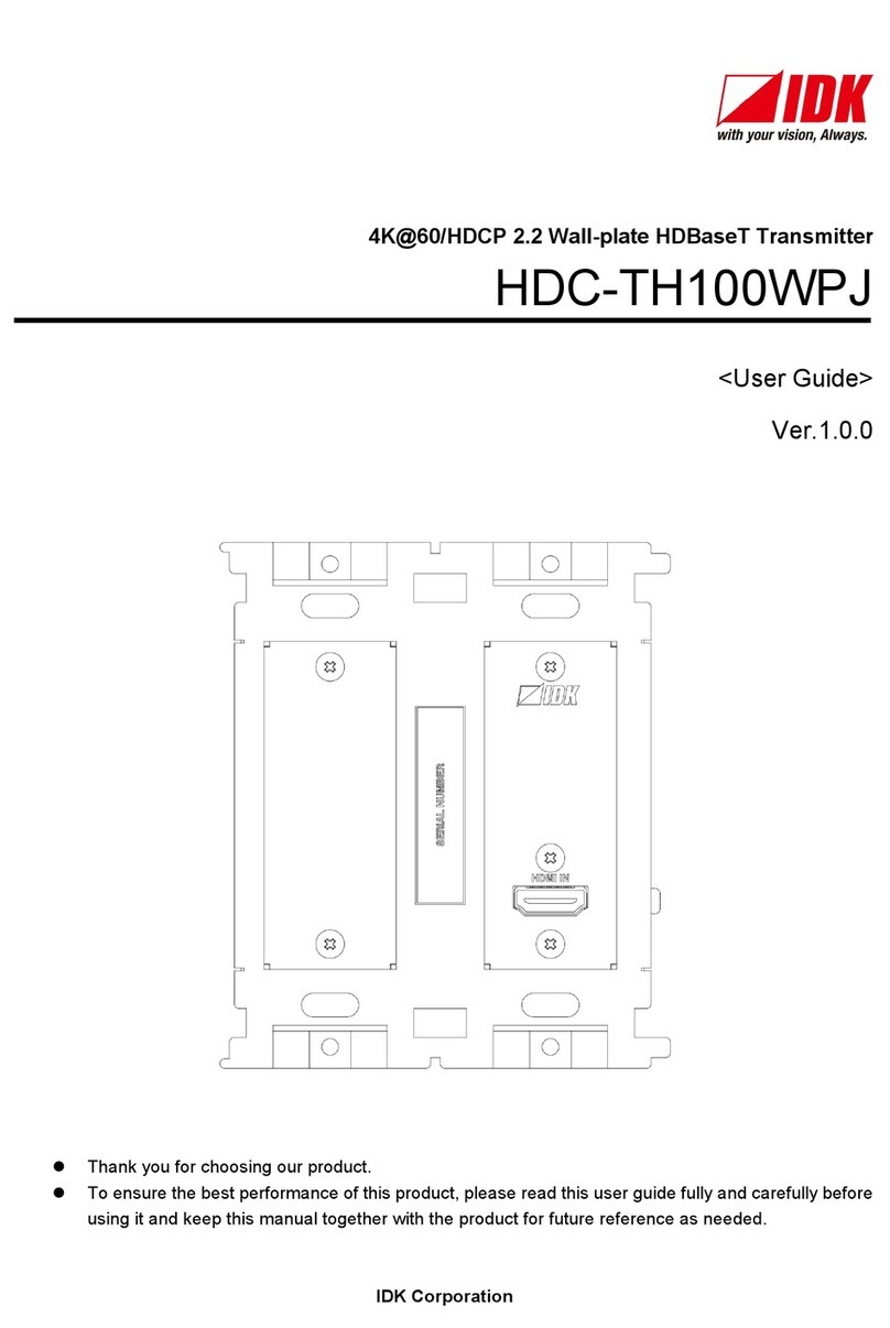
IDK HDC-TH200 User manual

HDMI/Analog HDBaseT Transmitter
HDC-TH200
<User Guide>
<Command Reference Guide>
Ver.1.4.0
⚫Thank you for choosing our product.
⚫To ensure the best performance of this product, please read this user guide fully and carefully before
using it and keep this manual together with the product for future reference as needed.
IDK Corporation

HDC-TH200 User Guide/Command Guide
2
Trademarks
⚫Blu-ray Disc and Blu-ray are trademarks of Blu-ray Disc Association.
⚫ETHERNET is a registered trademark of Fuji Xerox Co., Ltd.
⚫HDBaseT™ and the HDBaseT Alliance Logo are trademarks of the HDBaseT Alliance.
⚫The terms HDMI and HDMI High-Definition Multimedia Interface, and the HDMI Logo are trademarks or
registered trademarks of HDMI Licensing Administrator, Inc. in the United States and other countries.
⚫All other company and product names mentioned in this manual are either registered trademarks or
trademarks of their respective owners. In this manual, the “®” or “™” marks may not be specified.

HDC-TH200 User Guide/Command Guide
3
Before reading this manual
⚫All rights reserved.
⚫Some information contained in this User guide such as exact product appearance, diagrams, menu
operations, and so on may differ depending on the product version.
⚫This User guide is subject to change without notice. You can download the latest version from IDK’s
website at: http://www.idkav.com
FCC STATEMENT
This equipment has been tested and found to comply with the limits for a Class A digital device, pursuant to
part 15 of the FCC Rules. These limits are designed to provide reasonable protection against harmful
interference when the equipment is operated in a commercial environment. This equipment generates, uses,
and can radiate radio frequency energy and, if not installed and used in accordance with the instruction
manual, may cause harmful interference to radio communications. Operation of this equipment in a residential
area is likely to cause harmful interference, in which case the user will be required to correct the interference
at his own expense.
CE MARKING
This equipment complies with the essential requirements of the relevant European health, safety and
environmental protection legislation.
WEEE MARKING
Waste Electrical and Electronic Equipment (WEEE), Directive 2002/96/EC
(This directive is only valid in the EU.)
This equipment complies with the WEEE Directive (2002/96/EC) marking requirement.
The left marking indicates that you must not discard this electrical/electronic equipment in
domestic household waste.

HDC-TH200 User Guide/Command Guide
4
Safety Instructions
Read and understand all safety and operating instructions before using this product. Follow all instructions
and heed all warnings/cautions.
Enforcement Symbol
Description
Indicates the presence of a hazard that may result in death or serious
personal injury if the warning is ignored or the product is handled
incorrectly.
Indicates the presence of a hazard that may cause minor personal
injury or property damage if the caution is ignored or the product is
handled incorrectly.
Symbol
Description
Example
Caution
This symbol is intended to alert the user. (Warning and caution)
Electrical
Hazard
Prohibited
This symbol is intended to prohibit the user from specified actions.
Do not
disassemble
Instruction
This symbol is intended to instruct the user.
Unplug
Warning
Caution

HDC-TH200 User Guide/Command Guide
5
For lifting heavy products:
Instruction
●Lifting must be done by two or more personnel.
To avoid injury: When lifting the product, bend your knees, keep your back straight and get close to it with two or
more persons.
For installing and connecting products:
Prohibited
●Do not place the product upon a surface that may give way or that may become
unstable.
Install the product in a secure and stable place to prevent it from falling and possibly causing injury.
●Secure the product if installing in locations prone to vibration or movement.
Otherwise, it may move unexpectedly or it may fall and lead to injury.
Instruction
●Installation work must be performed by professionals.
The product is intended to be installed by skilled technicians. For installation, please contact a system integrator
or IDK. Improper installation may lead to the risk of fire, electric shock, injury, or property damage.
●Insert the power plug into an outlet that is unobstructed.
Unobstructed access to the plug enables unplugging the product in case of any extraordinary failure, abnormal
situation or for easy disconnection during extended periods of non-use.
●Insert the power plug into an appropriate outlet completely.
If the plug is partially inserted, arching may cause the connection to overheat, increasing the risk of electrical
shock or fire. Do not use a damaged plug or connect to a damaged outlet.
●Unplug the product from the AC power source during installation or service.
When connecting peripheral devices to this product, unplug all involved devices from outlets. Ground potential
differences may cause fire or other difficulties.
For operating products:
Prohibited
●Keep out any foreign objects.
To avoid fire or electric shock, do not permit foreign objects, such as metal and paper, to enter the product from
vent holes or other apertures.
●For power cable/ plug:
Do not scratch, heat, or modify, including splicing or lengthening them.
Do not pull, place heavy objects on them, or pinch them.
Do not bend, twist, tie or clamp them together forcefully.
Misuse of the power cable and plug may cause fire or electric shock. If power cables/plugs become damaged,
contact your IDK representative.
Do not
disassemble
●Do not repair, modify or disassemble.
Since the product includes circuitry that uses potentially lethal, high voltage levels, disassembly by unauthorized
personnel may lead to the risk of fire or electric shock. For internal inspection or repair, contact your IDK
representative.
Do not touch
●Do not touch the product and connected cables during electrical storms.
Contact may cause electric shock
Instruction
●Clean the power plug regularly.
If the plug is covered in dust, it may increase the risk of firer.
Warning

HDC-TH200 User Guide/Command Guide
6
If the following problem occurs:
Unplug
●Unplug immediately if the product smokes, makes unusual noise, or produces a
burning odor.
If you continue to use the product under these conditions, it may cause electric shock or fire.
●Unplug immediately if the product is damaged by falling or having been dropped.
If you continue to use the product under these conditions, it may increase the risk of electrical shock or fire. For
maintenance and repair, contact your IDK representative.
●Unplug immediately if water or other objects are directed inside.
If you continue to use the product under these conditions, it may increase the risk of electrical shock or fire. For
maintenance and repair, contact your IDK representative.
Warning

HDC-TH200 User Guide/Command Guide
7
For installing and connecting products:
Prohibited
●Do not place the product in a location where it will be subjected to high
temperatures.
If the product is subjected to direct sunlight or high temperatures while under operation, it may affect the
product’s performance and reliability and may increase the risk of fire.
●Do not store or operate the product in dusty, oil smoke filled, or humid place.
If the product is placed near humidifiers or in a dusty area, it may increase the risk of fire or electric shock.
●Do not block the vent holes.
If ventilation slots are blocked, it may cause the product to overheat, affecting performance and reliability and
may increase the risk of fire.
●Do not place or stack heavy items on the product.
Failure to observe this precaution may result in damage to the product and other property and may lead to the
risk of personal injury.
●Do not exceed ratings of outlet and wiring devices.
Exceeding the rating of an outlet may increase the risk of fire and electric shock.
No wet hands
●Do not handle power plug with wet hands.
Failure to observe this precaution may increase the risk of electrical shock.
Instruction
●Use and store the product within the specified temperature/humidity range.
If the product is used outside the specified range for temperature and humidity continuously, it may increase the
risk of fire or electric shock.
●Do not place the product at elevations of 1.24 mi. (2,000 m) or higher above sea
level.
Failure to do so may shorten the life of the internal parts and result in malfunctions.
●When mounting the product into the rack, provide sufficient cooling space.
Mount the product in a rack meeting EIA standards, and maintain spaces above and below for air circulation. For
your safety as required, attach an L-shaped bracket in addition to the panel mount bracket kit to improve
mechanical stability.
●Never insert screws without the rubber feet into the threaded holes on the bottom
of the product.
Never insert screws without the rubber feet into the threaded holes on the bottom of the product. Doing so may
lead to damage when the screws contact electrical circuitry or components inside the product.
Reinstall the originally supplied rubber feet using only the originally supplied screws.
For operating products:
Prohibited
●Use only the supplied power cable and AC adapter.
●Do not use the supplied power cable and AC adapter with other products.
If non-compliant adapter or power cables are used, it may increase the risk of fire or electrical shock.
Unplug
●If the product won’t be used for an extended period of time, unplug it.
Failure to observe this precaution may increase the risk of fire.
●Unplug the product before cleaning.
To prevent electric shock.
Instruction
●If cooling fan stops, power off the product and contact us.
Failure to do so may rise internal temperature and increase the risk of malfunction, fire, or electric shock.
●Clean the vent holes regularly.
If the vent holes of the cooling fan is covered in dust, internal temperature rises and it may increase the risk of
malfunction, fire, or electric shock.
Caution

HDC-TH200 User Guide/Command Guide
8
Table of Contents
1Included items.......................................................................................................................................... 10
2About HDC-TH200................................................................................................................................... 11
3Features................................................................................................................................................... 12
4Panels...................................................................................................................................................... 13
4.1 Front panel.......................................................................................................................................... 13
4.2 Rear panel .......................................................................................................................................... 14
5System Configuration Example................................................................................................................ 15
6Precautions.............................................................................................................................................. 16
6.1 Attaching Rubber feet......................................................................................................................... 16
6.2 Installation........................................................................................................................................... 16
6.3 Cabling................................................................................................................................................ 17
6.3.1 Cables......................................................................................................................................... 17
6.3.2 Category cable............................................................................................................................ 18
6.3.3 DIN plug AC adapter with locking mechanism............................................................................ 19
6.3.4 Analog video input connector...................................................................................................... 21
6.3.5 Connection between HDC-TH200 and MSD-402....................................................................... 22
6.3.6 RS-232C communication of HDBaseT output connector ........................................................... 22
7Basic operation ........................................................................................................................................ 23
7.1 Menu operations................................................................................................................................. 23
7.2 Locking menu operation keys............................................................................................................. 24
7.3 Initialization......................................................................................................................................... 24
7.4 Input channel remote switching.......................................................................................................... 25
8Menus ...................................................................................................................................................... 26
8.1 Menu list.............................................................................................................................................. 27
8.2 Input switching setting ........................................................................................................................ 30
8.2.1 [ F05 ] Priority of input channel automatic switching................................................................... 30
8.2.2 [ F06 ] Audio................................................................................................................................ 31
8.2.3 [ F00 ] Manual input channel switching....................................................................................... 32
8.3 Input.................................................................................................................................................... 33
8.3.1 [ F16 ] No-signal input monitoring............................................................................................... 33
8.3.2 [ F17 ] Digital input equalizer....................................................................................................... 34
8.3.3 [ F07 ] Analog input signal type................................................................................................... 34
8.3.4 [ F64 ] Color bit for analog video input........................................................................................ 34
8.4 EDID ................................................................................................................................................... 35
8.4.1 [ F01 ] Copying EDID.................................................................................................................. 35
8.4.2 [ F10 to F11 ] EDID resolution..................................................................................................... 36
8.4.3 [ F76 to F77 ] Selecting EDID WXGA......................................................................................... 37
8.4.4 [ F20 ] Deep Color....................................................................................................................... 38
8.4.5 [ F22 ] PCM Audio....................................................................................................................... 38
8.4.6 [ F24 ] AC-3 Dolby Digital Audio................................................................................................. 39
8.4.7 [ F26 ] AAC Audio ....................................................................................................................... 39
8.4.8 [ F28 ] Dolby Digital Plus Audio .................................................................................................. 40
8.4.9 [ F30 ] DTS Audio........................................................................................................................ 40
8.4.10 [ F32 ] DTS-HD Audio................................................................................................................. 41
8.4.11 [ F34 ] Dolby TrueHD Audio........................................................................................................ 41
8.4.12 [ F36 ] Audio channel.................................................................................................................. 42
8.4.13 [ F38 ] Copying EDID’s CEC physical address........................................................................... 43

HDC-TH200 User Guide/Command Guide
9
8.5 Analog video timing ............................................................................................................................ 44
8.5.1 [ F08 ] Automatic measurement.................................................................................................. 44
8.5.2 [ F40 ] Automatic measurement of start position........................................................................ 46
8.5.3 [ F42 ] The total number of horizontal dots................................................................................. 48
8.5.4 [ F43 ] Starting position of horizontal dots................................................................................... 48
8.5.5 [ F44 ] Horizontal Active area...................................................................................................... 49
8.5.6 [ F45 ] Horizontal start position................................................................................................... 49
8.5.7 [ F46 ] Display period of horizontal dots...................................................................................... 50
8.5.8 [ F47 ] Horizontal sync signal width ............................................................................................ 50
8.5.9 [ F48 ] Starting position of vertical lines...................................................................................... 51
8.5.10 [ F49 ] Vertical active area.......................................................................................................... 51
8.5.11 [ F50 ] Vertical start position........................................................................................................ 52
8.5.12 [ F51 ] Display period of vertical lines......................................................................................... 52
8.5.13 [ F52 ] Vertical sync signal width................................................................................................. 53
8.5.14 [ F53 ] Tracking........................................................................................................................... 53
8.6 Output................................................................................................................................................. 54
8.6.1 [ F65 ] Audio output..................................................................................................................... 54
8.6.2 [ F70 ] Deep Color output............................................................................................................ 54
8.7 Advanced setting ................................................................................................................................ 55
8.7.1 [ F90 ] Version............................................................................................................................. 55
8.7.2 [ F99 ] Maintenance/status display menu ................................................................................... 55
8.8 Checking operation (Maintenance menu)........................................................................................... 56
8.8.1 [ C01 ] Sink device EDID check.................................................................................................. 56
8.8.2 [ C06 ] HDCP input...................................................................................................................... 57
8.8.3 [ C10 ] Hot plug ignoring duration............................................................................................... 58
8.8.4 [ C14 ] RS-232C communication speed...................................................................................... 59
8.8.5 [ C15 ] RS-232C communication data bit length......................................................................... 59
8.8.6 [ C16 ] RS-232C communication parity check............................................................................ 59
8.8.7 [ C17 ] RS-232C communication stop bit.................................................................................... 59
8.8.8 [ C18 ] HDBaseT output long reach mode.................................................................................. 60
8.8.9 [ C30 ] Ignoring duration after automatic switching..................................................................... 60
8.8.10 [ C55 ] Forced output color mode ............................................................................................... 60
8.9 Displaying input/output statuses (Status display menu)..................................................................... 61
8.9.1 [ L00 ] Display selected input channel ........................................................................................ 61
8.9.2 [ L01 to L13 ] Displaying digital input information....................................................................... 62
8.9.3 [ L20 to L22 ] Displaying analog input information...................................................................... 64
8.9.4 [ L30 to L60 ] Output information ................................................................................................ 65
9Command................................................................................................................................................. 66
9.1 Summary............................................................................................................................................. 66
9.2 Command list...................................................................................................................................... 67
9.3 Details of commands .......................................................................................................................... 68
9.3.1 Error status.................................................................................................................................. 68
9.3.2 Input channel selection ............................................................................................................... 68
9.3.3 RS-232C communication............................................................................................................ 69
9.3.4 Advanced setting......................................................................................................................... 70
10 Specification............................................................................................................................................. 77
10.1 Product specification........................................................................................................................... 77
11 Troubleshooting....................................................................................................................................... 78

HDC-TH200 User Guide/Command Guide
10
1 Included items
Ensure that all items illustrated below are included in the package.
If any items are missing or damaged, please contact IDK.
One (1) main unit (HDC-TH200)
DIN plug AC adapter with locking
mechanism (3.9 ft. (1.2 m))
One (1) cable clamp
Four (4) Rubber feet
[Fig. 1.1] Included items

HDC-TH200 User Guide/Command Guide
11
2 About HDC-TH200
The HDC-TH200 is a transmitter for long-distance transmission of HDMI/DVI and Analog (video and audio)
input signals over a category cable.
Since HDMI/DVI signals are transmitted without compression or processing, the image quality can be kept.
Analog video signals can be converted to digital signal with high image quality by 12 bit quantization.
1 channel HDMI signal or DVI signal and one channel analog input video signals (composite, Y/C (S-Video),
RGB, and YPbPr) are supported. Selected input signal is converted to HDBaseT signal and output.
1 channel digital and analog audio is supported. Audio signal is embedded to video signal and transmit as
HDBaseT signal.
The HDC has LAN port as communication port and HDBaseT signal support bidirectional LAN
communication.
Digital video/audio
HDMI DVI Input
1
HDC-TH200
Digital video/audio/
communication for extension
HDBaseT Output
1
LAN
Up to 98 ft. (30 m)
Up to 328 ft. (100 m)*
1Port
Analog video
Composite
Y/C
RGB
YPbPr
Input
1
Analog audio
Unbalanced LR Input
1
A/D
conversion
EDID emulator
EDID emulator
A/D
conversion
Transmitter
Audio
switch
Video
switch
Input EQ
*For long reach mode, video signals up to 1080p (24 bit) can be transmitted to 492 ft. (150 m) at maximum
if using with IDK s HDBaseT products supporting 328 ft. (100 m) transmission.
[Fig. 2.1] Diagram

HDC-TH200 User Guide/Command Guide
12
3 Features
Video
Up to 1080p/QWXGA (Reduced Blanking)
HDCP 1.4
3D Y/C separation for NTSC and PAL signals
Automatic input signal equalization
Input: Up to 98 ft. (30 m)
Up to 328 ft. (100 m) over Cat6 cable
Anti-snow
Up to 492 ft. (150 m) in Long reach mode (1080p 60 Hz 24 bit or less)*1
Audio
Embedding
Communication
LAN
Control input
RS-232C (HDBaseT)
Others
EDID emulation
Input channel automatic switching
CEC (Pass-through)
Last memory
Connection Reset
Button security lockout
AC adapter with locking mechanism
*1 If exceeding 328 ft. (100 m) in Long reach mode, CAT.5E HDC, Cat5e STP, and Cat6 STP cables are
recommended.

HDC-TH200 User Guide/Command Guide
13
4 Panels
4.1 Front panel
[Fig. 4.1] Front panel drawing
[Table 4.1] Front panel features
#
Feature
Description
POWER LED
Shows power status of the HDC.
ON : Power is supplied to the HDC.
OFF : Power is not supplied to the HDC.
KEY LOCK LED
Shows key lock status of the HDC.
ON : Keys are locked
Blink: During key lock setting
OFF : Keys are unlocked
Seven-segment LED
Displays menu number, setting number, and setting status.
Menu operation keys
Selects and sets each menu. If you press “SET” keys for a while you
can lock/unlock keys.
See: 7.1 Menu operations
See: 7.2 Locking menu operation keys

HDC-TH200 User Guide/Command Guide
14
4.2 Rear panel
[Fig. 4.2] Rear panel drawing
[Table 4.2] Rear panel features
#
Feature
Description
POWER LED
Shows power status of the HDC
ON : Power is supplied to the HDC.
OFF: Power is not supplied to the HDC.
Analog video input
connector
Input connector for analog video signal Following analog signals can
be input.
Analog RGB (such as PC)
Analog YPbPr (SDTV/HDTV)
Composite video (NTSC/PAL)
S-Video (NTSC/PAL)
See: 6.3.4 Analog video input connector
Audio input connector
Input connector for analog audio input
HDMI input connector
Input connector for HDMI signals
Connector for a source device such as a DVD/Blu-ray player
HDMI cable fixing hole
Holes for the supplied cable clamps to fix the HDMI cables
See: [Fig. 6.2] Securing and removing cable clamp
HDBaseT output
connector
Output connector for HDBaseT signal
Connecting HDBaseT receivers using twisted pair cable
See: 6.3.2 Category cable
See: 8.8.8 [ C18 ] HDBaseT output long reach mode
LAN port
LAN port connector
Connecting network devices
Connector for
maintenance
Not used. Please do not connect anything; this connector is for
maintenance only.
DIN connector
Connecting attached AC adapter
See: 6.3.3 DIN plug AC adapter with locking mechanism
Frame ground
Using M3 screw
Connecting ground terminal

HDC-TH200 User Guide/Command Guide
15
5 System Configuration Example
Laptop Blu-ray player
Speakers
Analog audio
Monitor
LAN
PC
Power amp.
Laptop
HDBaseT
Up to 328 ft. (100 m)
HDMI/DVI
Up to 7 ft. (2 m)
HDBaseT
Up to 328 ft. (100 m)
HDBaseT
Up to 328 ft. (100 m)
HDC series
receiver
HDMI/DVI
Up to 7 ft. (2 m)
Blu-ray player
HDMI/DVI
Up to 98 ft. (30 m)
HDMI/DVI
Up to 98 ft. (30 m) HDMI/DVI
Up to 16 ft. (5 m)
Projector
Rx
RS-232C
LAN
Cat6Rxfor HDMI
POWER LINK HDC P
STATUS POWER LINK HDCPPOWER LINK HDC P
STATUS
FG DC5V 2A
HDC-RH100-C
INPUT
DON'T
CONNECT
LAN
HDBaseT
CAUTION
!
(MAX2M)
HDMI
OUTPUT
HDC series
transmitter
RS-232C
LAN
Tx
Cat6Txfor HDMI
POWER LIN K HDCP
STATUS POWER LINK HDCPPOWER LINK HDCP
STATUS
INPUT
(MAX2M)
OUTPUT
FG DC5V 2A
DON'T
CONNECT
LAN
HDC-TH100-C
HDBaseT
CAUTION
!
HDMI
HDC-TH200
Blu-ray player
MSD-402
HDMI/DVI
Up to 98 ft. (30 m)
Analog RGB
DVD player
Composite
video Analog YPbPr
VHS
Y/C
Video camera
[Fig. 5.1] System configuration example

HDC-TH200 User Guide/Command Guide
16
6 Precautions
Before connecting to external devices, follow the precautions below.
6.1 Attaching Rubber feet
First, clean the bottom surface of the HDC as needed, and then peal the release papers from the rubber feet
and place them in each of the four corners.
6.2 Installation
When installing the HDC, please observe the following precautions.
Do not stack or place the HDC directly on top of another HDC
Do not block vent holes. To provide adequate ventilation, maintain sufficient clearances around the HDC
(1.2 in. (30 mm) or more)
When the HDC needs to be mounted in an enclosed space, ensure that a sufficient ventilation/cooling
system is provided to keep the ambient temperature at 104°F (40°C) or lower. If inadequately vented, the
product’s service life, operation, and reliability may be affected.
Maintain adequate clearances (1.2 in. (30 mm) or more) as shown below
Bad example
Good example
Good example
[Fig. 6.1] Necessary clearances

HDC-TH200 User Guide/Command Guide
17
6.3 Cabling
When connecting the HDC to external devices, please observe the following precautions.
Read manuals for the external devices.
Before connecting cables to the HDC or an external device, dissipate static electricity by touching
grounded metal such as equipment racks before handling signal cables. Failure to observe this precaution
may result in ESD (electrostatic discharge) damage.
Power all units off before connecting cables.
Be sure to fully seat all plugs and connections and dress cables to reduce stress on connectors.
Secure HDMI cables using cable clamps to prevent connectors from being accidently pulled out of ports.
Click
Securing HDMI cable using cable clamp
Removing HDMI cable and cable clamp
Pull out while pressing
[Fig. 6.2] Securing and removing cable clamp
6.3.1 Cables
Use the correct HDMI cable or HDMI-DVI conversion cable depending on the system configuration.

HDC-TH200 User Guide/Command Guide
18
6.3.2 Category cable
To ensure the best performance with category cables, select a high quality category cable type, ensuring that
proper pinning and pairing requirements are observed.
Cat5e UTP/STP and Cat6 UTP/STP can be used, but we recommend CAT.5E HDC cable* for optimal
performance.
If using STP cables, connect the FG connector to a local electrical ground bonding point. Without bonding
FG to ground, the shielding feature may not effectively eliminate interference. If using UTP cables, it is still
recommend that the FG connector be used.
The STP cables are less affected by interference or external noise than UTP cables.
Connectors for long-haul transmission are the same as that of eight-core modular connector used for
Ethernet, but the transmission system is not the same so that it cannot be connected to Ethernet.
The maximum transmission distance of a category cables is the shorter distance of the maximum
transmission distances of transmitter/receiver/sink device connected to the HDC.
Pin assignments: T568A or T568B straight
Do not pull the cable using excessive force. The allowable tension of the category cable is 110 N.
Do not bend the cable at a sharp angle. Keep the bend radius four times of the cable diameter or larger.
Do not clamp or tie the cable tightly; leave some space allowing the cable to move slightly.
If you use multiple category cables, we recommend keeping a distance between the cables or not to place
the cables closely in parallel.
Keep the category cable running as straight as possible. Looping or coiling the cable, causes it to be more
easily affected by noise; especially when using longer cable run lengths.
Do not place the cable in an electrically noisy environment, since high-speed impulsive noise may couple
into the category cable. Use of a high-output radio transmission device near the HDC or remote receivers
may interfere with or interrupt video and or audio signals.
If the total transmission distance from the transmitter to receiver is 328 ft. (100 m) or less, up to two cable
interconnection points can be used. Products supporting Cat6A (10GBase-T) are recommended.
The table below shows supported transmission distance for each category.
Note that specified distances may shorten depending on the conditions within the actual environment.
[Table 6.1] Transmission distance
Noise
influence
Category
Transmission
distance
TMDS clock
Recommended cable
Easily
affected
UTP
Cat5e
164 ft.
(50 m)
225 MHz
For 164 ft. (50 m) or longer:
CAT.5E HDC*, Cat5e STP,
and Cat6 UTP/STP cables
Cat6
328 ft.
(100 m)
Less
affected
STP
Cat5e*
Cat6
328 ft.
(100 m)
492 ft.
(150 m)
Long reach mode
148 MHz
(1080p (24 bit) or less)
For 164 ft. (50 m) or longer:
CAT.5E HDC*, Cat5e STP,
and Cat6 UTP/STP cables
*The CAT.5E HDC cable is a double-shielded category cable optimized for video signal transmission.
The double-shielded structure protects the video signal from external interference. It is certified to
500 MHz bandwidth at distances up to 328 ft. (100 m) and verified to meet requirements specified by
HDBaseT Alliance.

HDC-TH200 User Guide/Command Guide
19
Note:
If there is a problem in the transmission path, video or audio may be interrupted. Check the “[Table 6.1]”
above.
If the problem persists, it may be necessary to shorten the category cable.
6.3.3 DIN plug AC adapter with locking mechanism
The shapes of AC plugs with screw locking mechanism vary from country to country. The AC plug can be
removed from the AC adapter.
Removing AC plug:
Slide the AC plug () from the AC adapter while holding down the portion mentioned below ()
①
②
[Fig. 6.3] Removing AC plug (Example: Plug type A)
Attaching AC plug:
Gently slide the AC plug into the AC adapter () until it clicks ()
③
④
This tab should be fixed into
the part of the AC adapter.
Tab
[Fig. 6.4] Attaching AC plug (Example: Plug type A)

HDC-TH200 User Guide/Command Guide
20
Plugging and unplugging DC plug
Plug the DC plug to the power supply connector of the unit until it clicks
Hold the portion mentioned below when unplugging the DC plug
Plugging Unplugging
Hold this part and pull
the DC plug
[Fig. 6.5] Plugging and unplugging DC plug
Other manuals for HDC-TH200
1
Table of contents
Other IDK Transmitter manuals