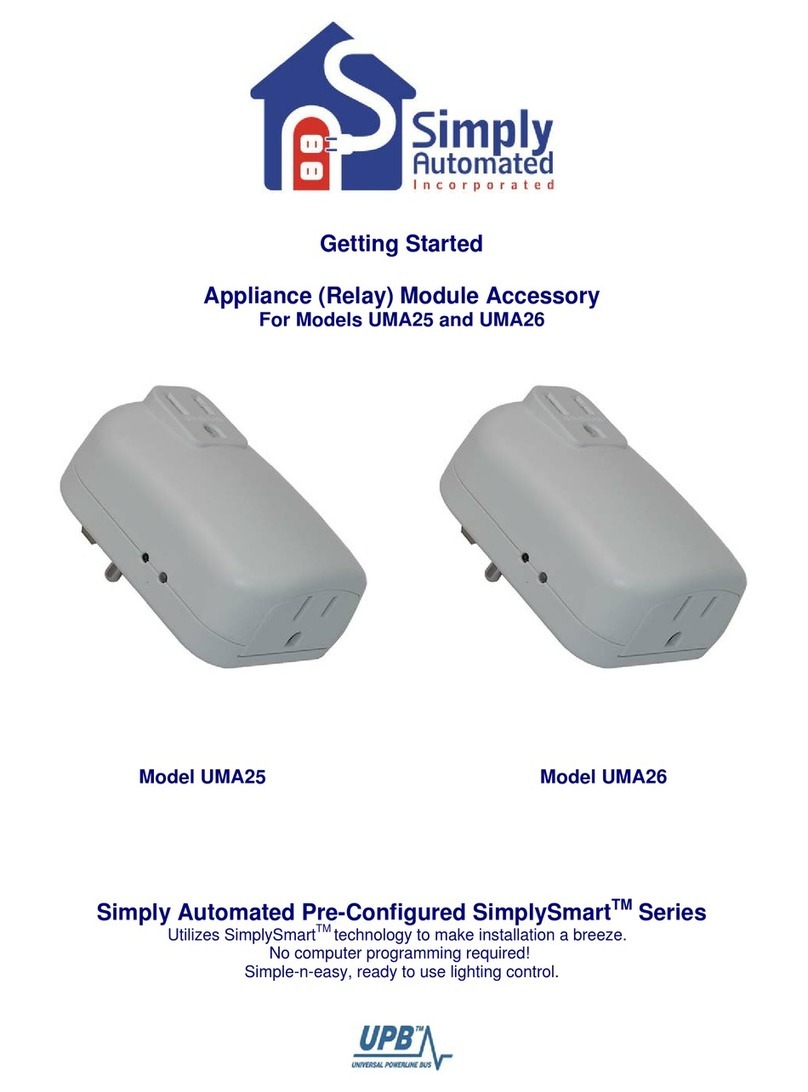
iDomotics Starter Kit User manual

QUICK INSTALLATION GUIDE


This product must be installed by a
licensed electrician or other suitably
qualied person.
IMPORTANT NOTE
Please read the following document
carefully before setting up and using your
IDOMOTICS device for the rst time.

4
content
Tools required
Controller
Sensor Network
cable
Domotic
Central
3 mm athead
screwdriver
Voltage tester
screwdriver
Stripping tool 0,5 or 0,75 mm cable
20 mm hole saw
Power source
7.5 volts
1 ampere

5
central
Connections
USB
Supply
Connect it to the Switch
or to your Router’s LAN port.
Network
cable
RJ-45 input
USB
Optional use
of power
supply.
For the use of
Technical
Personnel.

6
Connection of Light controllers
- Neutral cable inside the light box needed.
- Works with one or two lights.
- T1 corresponds to light 1, T2 to light 2.
Important: Do not connect the keys to the domestic
supply network.
| Connection of Light controllers
Conguration
button
Keys
connection
Electrical
connection
Domestic
network
21

7
Installation of Light controllers
For lament light bulbs, low energy bulbs, LED (110-
220V), uorescent tubes, dichroic bulbs (110-220V).
1. Dismantle the frame. If you use the light and tempera-
ture sensor, at least one blind module is required.
2. Identify the return conductor of the lamps and the line
or phase cable, using a voltage tester screwdriver. If you
can’t nd one, add a neutral cable, which will be neces-
sary for the performance of the controller.
-OPTIONAL-
3. Take the blind module o the frame and make a
20mm hole in the middle with the holesaw. A power
driver is recommended for this.
4. Disconnect the sensor’s module from the light
switch controller and press it onto the hole of the blind
module. We recommended gluing it in place with silico-
ne or multipurpose glue.
Extreme care: handling objects with electrical
voltage! Danger of electrocution!
Proceed only trained electrician or other suitably
qualied person. We recommend placing the
controller next to the light switch.
Installation of Light controllers |

8
5. Cut three cables with a maximum length of 8cm and
connect them to the corresponding terminal board of C,
T1 and T2 of the controller’s keys. It is recommended
that you do not strip the cable more than 5mm with the
cable stripper.
6. Disconnect the returns from the keys of the frame
and connect them to the terminals 1 and 2, and Line and
Neutral to the terminals L and N. Use a 3 mm athead
screwdriver.
N: Neutral cable
L: Line or Phase cable
1: Light return 1
2: Light return 2
See the installation diagram to verify the connections.
7. Connect the cables connected to the frame of the
light switch controller to the keys of the frame, then con-
nect the module to the sensors. (See diagram of connec-
tion of Light Controller)
C: Common
T1: Light controller 1
T2: Light controller 2
| Installation of Light controller
IMPORTANT. CUT THE ELECTRICITY OF THE RESIDENCE
BEFORE CONTINUING.

9
Introduce it in the metal case inside the wall but DO
NOT close it with the frame. Install the rest of the
controllers before continuing.
8. Connect the electricity of the residence and proceed
to install the central.
9. With the idomotics server installed and congured,
add the corresponding device. ( see page 13 of the User
manual)
Move the handle named ‘CONFIG’ on the light controller
to its opposite side.
Once you can see the ‘identier’ code on the congura-
tion of the device, close with (see page 14 of the User
manual)
10. You can now see and operate the controller on the
client app. Proceed to adjust the frame.
Installation of Light controllers |
LAN
Connect it to
the Switch
or Router’s LAN
port.
USB
Optional
connection for
power supply.
CENTRAL’S
BACK
SUPPLY
Connect it to
the plug with the
power source included.

10
Uses: Light Controller
How to connect it to the electric lock.
| Uses of light controller
Doorbell
button
Electrical
connection
Electric lock
which unblocks
the latch
Conguration
button
Domestic
network

11
How to connect it to an air conditioner.
Uses of light controller |
Electrical
connection
Electromagnetic
contactor or
Solid State Relay
(SSR)
Domestic
network
Charge
110/220 V A C control
Conguration
button
- NOTE: if the control uses an SSR, it only shuts o one power pha-
se and the other one remains constantly connected to the charge.

12 | Connection of the RGB controller
Connection cables
of LED strip
Connection of the RGB controller
RGB
LED light
G R
12V power
source
12V power
source
Drilling to
adjust the
controller
to the wall
Conguration
button
Drilling to
adjust the
controller
to the wall
Conguration
button

13
Installation of the RGB controller
For LED or monocolor light strips / 12 VDC RGB with
common positive up to 2 A per channel.
1. Take the controller to the place where it will be con-
nected to measure the length of the cable needed, taking
into account the 12V power source cable.
2. Strip the cables which connect the RGB, up to 5mm
with the cable stripper.
3. Proceed to connect the lights.
RGB lights:
+: positive of RGB light
G: colour green
R: colour red
B: colour blue
For monocolor lights:
+: positive of the three lights
G: negative of light 1
R: negative of light 2
B: negative of light 3
*It’s not necessary to connect the three lights.
See the installation diagram to verify the connections.
Installation of the RGB controller |

14
Use a 3mm athead screwdriver.
4. Connect the power source.
Install the rest of the controllers before continuing,
and connect them to terminals 1 and 2, and Line and
Neutral to L and N.
5. Proceed to install the central.
6. Add the corresponding device when the idomotics
server is already installed and congured. (See page 13 -
Conguration manual)
Press the button named ‘CONFIG’ on the RGB controller
once, with a slim item.
Once you can see the ‘Identier’ code on the conguration
of the device, close pressing (See page 14 - Congura-
tion manual)
| Installation of the RGB controller
LAN
Connect it to
the Switch
or Router’s LAN
port.
USB
Optional
connection to
power supply.
CENTRAL’S
BACK
SUPPLY
Connect it to
the plug with the
power source included.

15
7. You can now see and operate the controller on the
Client app.
Proceed to adjust the controller.
Installation of the RGB controller |

Skype: support.idomotics
E-mail: [email protected]
· To download the manuals:
INSTALLATION
http://www.idomotics.com/download/idomoticsInstalla-
tion.pdf
CONFIGURATION
http://www.idomotics.com/download/idomoticsCongura-
tion.pdf
· Learn more:
You can nd more information about idomo-
tics and its features on:
www.idomotics.com
Table of contents
