iDTRONIC ID Lock 5000 User manual

ID LOCK 5000
Manual
Rev. 01 | English | 2
5
123
4
789
0
6
The ID LOCK 5000 impresses with its versatile applications
and installation options. This innovative design lock offers
the possibility of individual time control with adjustable lock
duration and up to 999,999 code variations.
The code variant allows for both recessed installation
(Flush-Fit) and retrofitting (Retro-Fit). With the option of
one, two, or three-point locking with a latch function, it
conveniently adapts to any installation situation.
Important: Please pay attention to all warning notices
and read the entire user manual before starting the
configuration.
Introduction
The latest version of this manual is available at:
www.idtronic-wellfit.de
www.idtronic-secureaccess.de
General
ID LOCK 5000
2
2
3
3
3
3
3
3
4
5
6
7
8
8
Introduction
General
Technical data
Scope of delivery
Optional accessories
Default-settings
Features
Product dimensions
Functional descriptions
Installation
Flush-Fit
Installation
Retro-Fit
Configuration
Operatio n
Battery change
Disposal and battery notice 8
Content
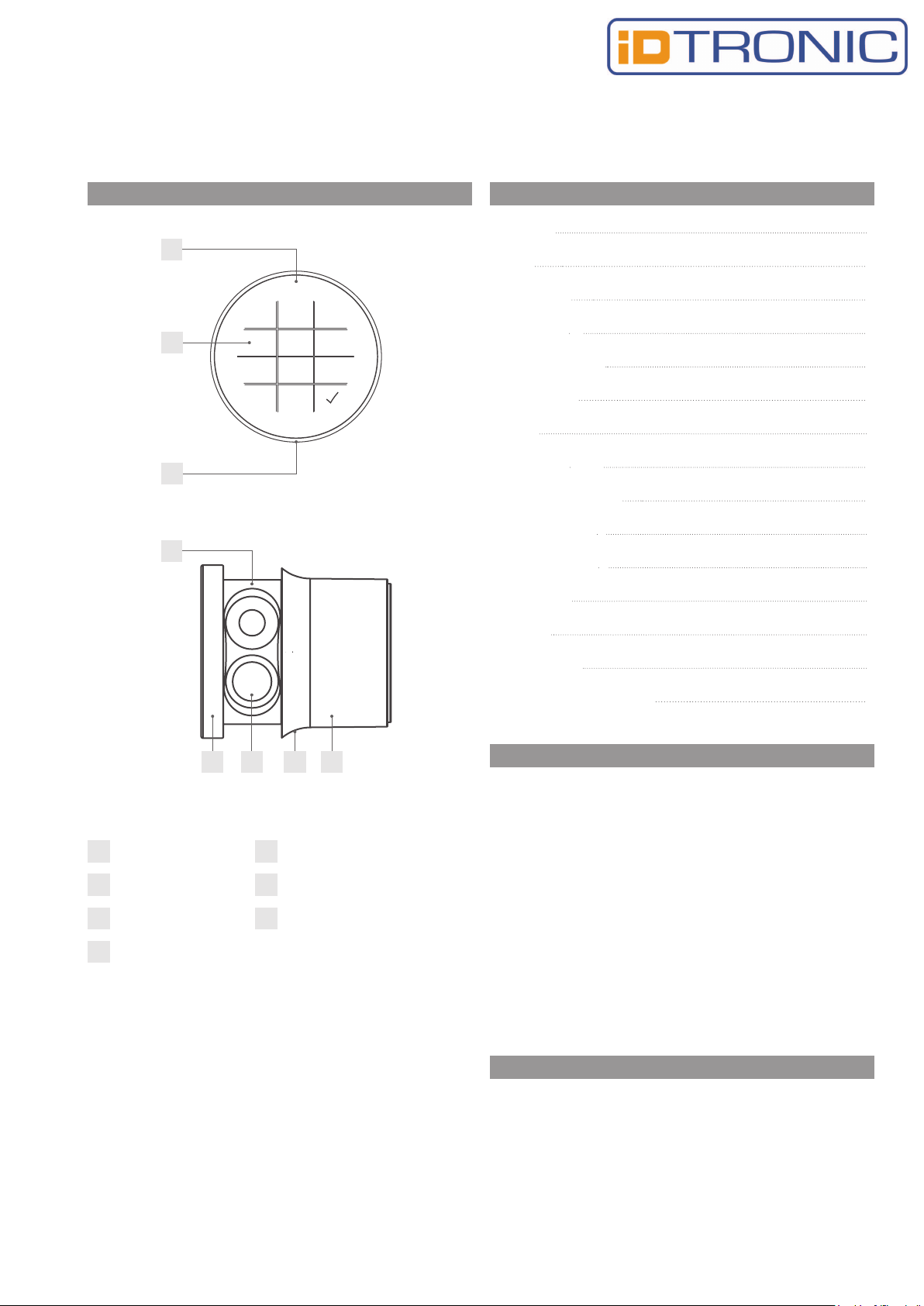
B
A LED B Touchpad buttons
C Opening hole D Battery compartment
E Battery F Knob
G Casing
A
D
EF GC
C
ID LOCK 5000 | 07-2023
Rev. 01 | English | 3
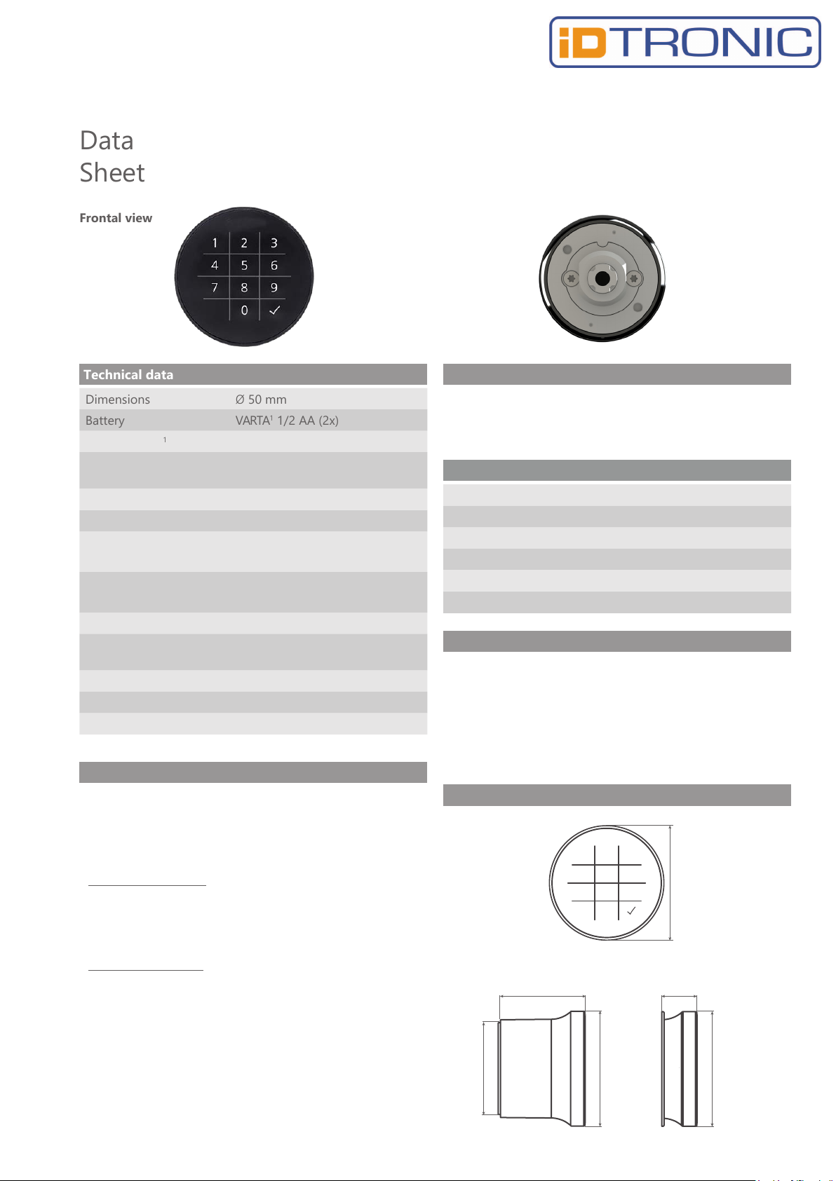
Dimensions
Battery
Closing cycles1
Ø50 mm
VARTA1 1/2 AA (2x)
30.000
Temperature range -20° C to 55° C
rel. Humidity: 10% - 85%
Amt. possible codes 999.999
PIN-Length
Mode
Material
Installation dimensions
4 or 6 digits
Multiuser-mode,
Private-mode
Casing: Plastic
Latch: Steel
16 mm x 19 mm
Closing directions Left (90°), Door handing:
DIN right
Lock mounting
Latch type
Max. door thickness
M19 Nut (1x)
B
22 mm
Technical data
Data
Sheet
Frontal view
Rear view
Ergonomic handling and premium design
External battery access and battery replacement
Time-controlled opening and closing
Features
Optional accessories
Twist protection (W-MSZ-01)
Opening needle
Fastening nut
Scope of delivery
1x Closing Unit
1x Latch mounting screw2 M6 x 12 mm
1x M19 Nut
Latch Type B, at
Individual packaging:
1x length 53 mm, without offset (1-36 RIH-501 G)
1x length 40 mm, with offset 3 mm (1-36 RIH-514 K)
1x length 40 mm, with offset 6 mm (1-36 RIH-515 K)
Industrial packaging: Latch customized order
Easy retrofitting, for example, to replace
mechanical locker locks
Adjustable latch (in 90° increments)
Product dimensions
Frontal view
Side view
Retro-Fit Flush-Fit
5
123
4
789
0
6
50 mm
43 mm
38,4 mm
50 mm
15 mm
50 mm
Master-code 934716
Mode Multiuser-mode
PIN-Length
Locking mechanism
4 digits
Manual
LED-lock-indicator On
Confirmation-code Off
Default-settings
1 The lock is approved for use with VARTA brand batteries. The
use of other batteries may result in a reduced number of possible
locking cycles.
2 Using a screw with a different length can lead to damage to the
lock.
ID LOCK 5000 | 07-2023

Rev. 01 | English | 4
Mode: Fixed permission (Private-mode)
In this mode, a pre-set PIN is used to operate the lock. This
mode is suitable for user groups where user permissions
should not change permanently, such as an office cabinet. The
lock is always in the locked state and opens for 4 seconds
upon entering the private PIN. The lock can be opened again
by entering a saved PIN. Up to 50 PINs can be stored. An
unsaved PIN will be rejected by the lock.
Mode: Multiuser permission (Multiuser-mode)
This mode is suitable for constantly changing users who only
use the compartment temporarily or once, such as in a sports
facility. The PIN is valid for a single locking operation and is
deleted by the lock when the compartment is reopened. The
lock remains in the open state until it is locked again. Before
locking, the door must be closed (lightly pressed). The user
enters a PIN of their choice (4 or 6 digits) to lock it. The green
LED briefly flashes. The lock is opened by entering the same
PIN.
Confirmation-code (Multiuser-mode)
To lock the lock, the PIN must be entered twice. Only after the
second entry, the lock will be locked. The second entry is
made after a brief flash of the green LED. To unlock, a single
PIN entry is sufficient. This function can be turned on or off.
Master-code
The master-code is used to authorize the programming of the
lock. Additionally, the master-code can open the lock
regardless of the set mode (emergency opening) and end the
lockout-mode. In the multiuser-mode, the PIN used for
locking is deleted after entering the master-code.
Note: We recommend programming a personal master-code
before using the lock.
LED lock indicator
The lock indicates the locked state by blinking the red LED
every second. This function can be turned on or off.
Automatic Locking (Private-mode)
The lock automatically closes after three seconds of opening.
The door does not need to be closed for this to occur. With
the latch function, the door can also be closed with the lock
engaged by lightly pressing it. This function can be turned on
or off.
Functional descriptions
Functional descriptions RTC
The ID LOCK 5000 also features an integrated software real-
time clock (RTC) that allows for programming time-based
functions. The functions and the defined times need to be
specified at the time of ordering.
Automatic Locking and Unlocking
The lock automatically locks and unlocks at a defined time.
The times can be set separately for each day of the week.
Usage Timeframe
The lock can only be operated within the individually defined
usage timeframe. Operation is not possible outside of the
specified timeframe. The times can be set separately for each
day of the week.
Locking Duration
The locking duration defines the period for which a lock can
remain closed after being locked. After the expiration of the
locking duration, the lock will automatically open.
Battery warning
If the battery capacity drops below a certain threshold, the
red LED will light up for three seconds after entering the PIN.
When the critical level is reached, the lock cannot be locked
anymore, or it can only be opened with the master-code.
Note: We recommend replacing the battery after the first
warning indication.
Lockout-mode
After three consecutive failed opening attempts, the lock
enters a lockout-mode for 45 seconds. During this period, no
action can be taken on the lock. The lockout time is indicated
by the red LED blinking once per second. The lockout-mode
can be prematurely lifted by entering the master-code.
ID LOCK 5000 | 07-2023

Rev. 01 | English | 5
Installation Flush-Fit
Prepare the installation hole on the door front
according to the installation dimensions described
below.
From the front, insert the ID LOCK 5000-ring into the
installation hole on the exterior side of the door and
hold it in place. Check if the ID LOCK 5000-ring is fully
seated on the exterior side of the door. Pay attention to
the correct position of the internal mounting opening.
From the back, secure the mounting nut with the ID
LOCK 5000-ring. Tighten the nut firmly by hand.
Insert the lock body from the exterior side of the
door into the opening of the ID LOCK 5000-ring.
1
2
3
4 Place the mounting nut onto the lock from the back.
Use a socket
wrench (size 22) to tighten the nut securely.
Install the latch and secure it with the included Torx
screw (Torx 30).
Subsequently, check if the latch adequately secures
against the strike plate or the door jamb in the closed
position. The latch should be able to rotate to its final
position when closing the locking system without any
pressure or resistance.
Installation dimensions
The dimensions for the installation hole on the exterior
side of the door apply to installation in wood, HPL, and
steel fronts.
5
6
45mm
¯47mm
Note: The drawings
provided alongside are not
to scale and should not be
used as templates for
milling.
ID LOCK 5000 | 07-2023
Rev. 01 | English | 6
Attach the latch and secure it with the provided Torx
screw (Torx 30).
Next, check if the latch securely engages with the
strike plate or the door jamb in the closed position.
The latch should rotate to its final position when
closing the locking system without any pressure or
resistance.
Note: The use of an adjustable strike plate allows for
optimal adjustment of the closing mechanism.
Installation dimensions
The dimensions for the installation hole on the exterior
side of the door apply to installation in wood, HPL, and
steel fronts.
Installation Retro-Fit
Prepare the installation hole on the door front according
to the installation dimensions described below. Note
that for wood and MDF fronts, a customized two-stage
recess may need to be milled. This recess is not
necessary for metal fronts.
Insert the lock body from the exterior side of the door
into the installation hole.
Place the mounting nut onto the lock from the back.
Use a socket wrench (size 22) to tighten the nut
securely.
1
2
3
4
5
16mm
¯19mm
Note: The drawings
provided alongside are not
to scale and should not be
used as templates for
milling.
ID LOCK 5000 | 07-2023

Rev. 01 | English | 7
Configuration
Please pay close attention to the following
instructions before starting the configuration:
Each configuration step is initiated by pressing the hook
button twice, followed by the corresponding digit.
Each configuration step is completed with a double blink
of the green LED.
The next configuration step can only be initiated after the
double blink of the green LED.
If the red LED blinks rapidly eight times in a row, the
configuration step was not executed correctly
1 Master-code
1 Mode Selection
a) Private-mode
Enter Master-code
Set mode
Note: To assign private PINs, please proceed to step 3a
"Assign PIN."
b) Multiuser-mode (default)
Enter Master-code 1 Master-code
Set mode
Note: After changing the mode, all functions will be reset
to their default settings. This does not apply to the master-
code.
2 Set PIN length
Enter Master-code
Choose number of digits
Note: After changing the number of digits, all PINs
stored in private-mode will be deleted.
3 Set Functions
a) Configuration in Private-
mode
Assign PIN
Enter Master-code
Assign PIN
Note: Up to 50 PINs can be stored. Depending on the set PIN
length, these must be either 4 or 6 digits long.
Delete PIN
Enter Master-code
Delete PIN
Note: Enter the PIN you want to delete.
Automatic Locking
Enter Master Code
Activate
Deactivate
b) Configuration in Multiuser-mode
Confirmation-code
Enter Master-code
Activate
Deactivate
c) Set General Functions
Set Custom Master-code
Enter the old master-code.
Note: The master-code must be 6 digits long.
LED lock indicator
Enter Master-code
Activate
Deactivate
Operation
1 Operation in Private-mode
Close Enter PIN
Open Enter PIN
2 Operation in Multiuser-mode
Close Enter PIN
Open Enter PIN
Note: When the confirmation-code is enabled,
the PIN must be entered twice when closing the
lock.
5 0
5 1
1 Mastercode
0 x
4 digits: x = 4
6 digits: x = 6
1 Master-code
3 xxxx (xx)
1 Master-code
9 xxxx (xx)
1 Master-code
6 1
6 0
2 0
2 1
1Master-code
1 Master-code
8 1
8 0
ID LOCK 5000 | 07-2023
Enter the new master-code
1 Master-code
7 xxx xxx

Rev. 01 | English | 8
Enter the Master-code
The master-code can open the lock regardless of the set
mode, initiate configuration, or end the lockout-mode.
When entering the master-code, please pay attention to
the following
note:
Always start entering the master-code by pressing the
hook button twice, followed by the digit 1.
Enter Master-code
1 Master-code
Note: When opening in multiuser-mode using the
master-code, the PIN used for locking will be deleted
after entering the master-code.
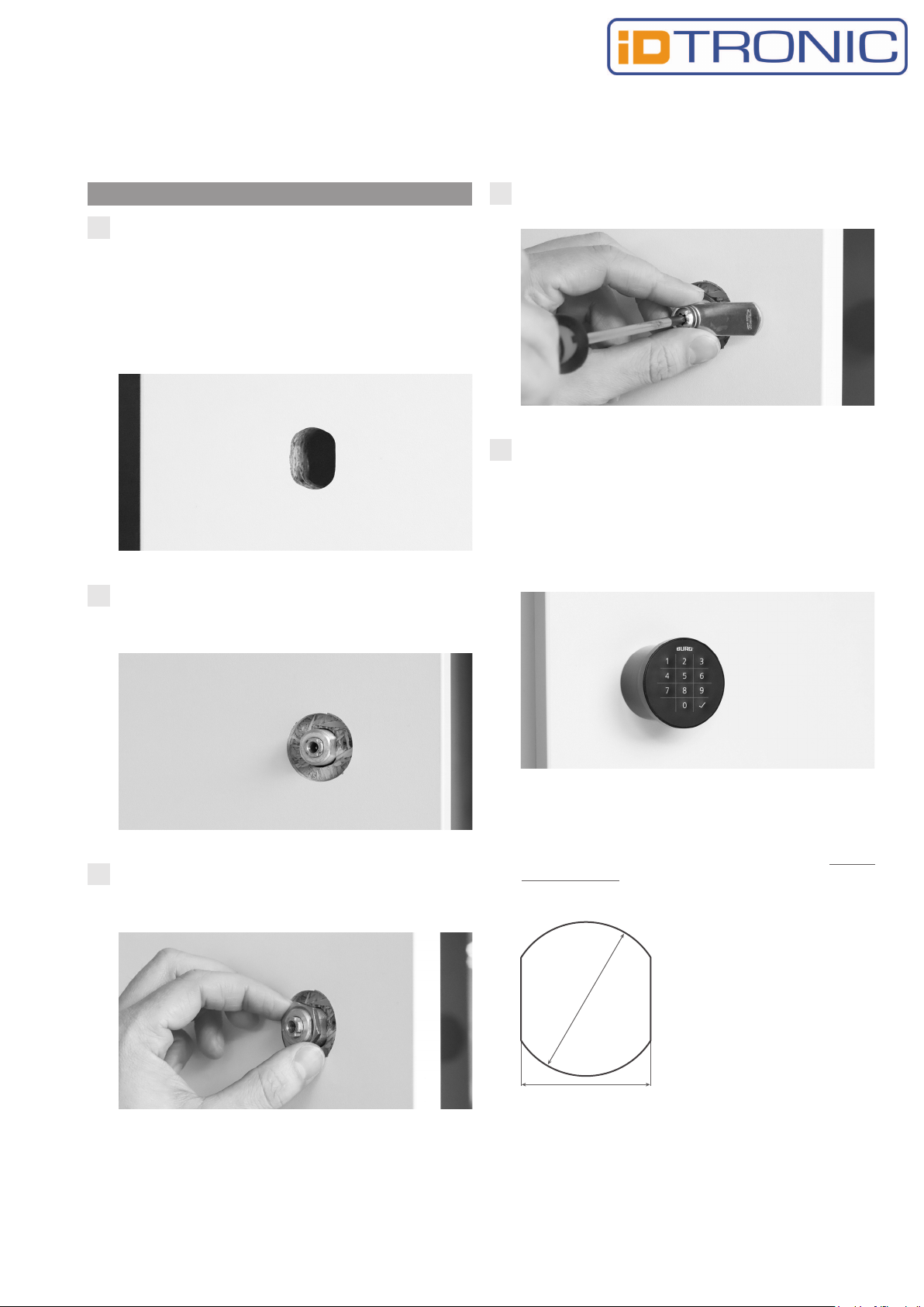
Battery change
1. Insert the opening pin, according to the illustration, into
the opening at the bottom of the lock. Gently move the
pin counterclockwise and pull the knob forward.
2. Open the battery cover and replace the batteries. Insert
the new batteries according to the symbols (+/-) indicated.
Note: The surface of the batteries must be free from residues
and fingerprints, as this can cause disruptions. If the surface
is dirty, it should be cleaned with a dry cloth.
3. Close the battery cover, push the knob back onto the lock,
and rotate the housing until it clicks into place.
Note: The lock is designed for use with VARTA brand
batteries. The use of other batteries may result in a reduced
number of possible locking cycles.
Disposal and battery notice
The EU Directive 2012/19/EU regulates the proper
collection, treatment, and recycling of used electronic devices.
Every consumer is legally obliged to dispose of batteries,
accumulators, or electrical and electronic equipment ("waste
equipment") that are operated with batteries or accumulators
separately from household waste, as they contain hazardous
substances and valuable resources. Disposal can be carried out
at designated collection or take-back points, such as local
recycling centers. Electrical waste equipment, batteries, or
accumulators are accepted there free of charge and undergo
environmentally friendly and resource-efficient recycling.
Used electrical waste equipment, batteries, or accumulators can
also be sent back to us. The return shipment must be
sufficiently stamped and sent to the address provided below.
The following symbol on electrical waste equipment, batteries,
or accumulators indicates that they must not be disposed of
with household waste:
Caution when using batteries!
The battery may explode or release flammable gases if
mishandled, damaged, or if the wrong battery type is used.
Do not recharge, disassemble, expose to extremely high
temperatures, or throw the battery into the fire. On batteries
containing hazardous substances, you will find abbreviations
indicating the presence of Cadmium (Cd), Mercury (Hg), and
Lead (Pb) as ingredients.
iDTRONIC
Ludwig-Reichling-Straße 4
67059 Ludwigshafen am Rhein
+49 621 669 009 20
Ver 1.2 | 10.7.23
ID LOCK 5000 | 07-2023
Other manuals for ID Lock 5000
1
Table of contents
Other iDTRONIC Keypad manuals

Popular Keypad manuals by other brands


Crestron
Crestron Cameo C2N-CBD-P Installation & operation guide

Vasco
Vasco Digipass 270 user manual

Genie
Genie GUK-BX instructions

Salto
Salto CONLAN CM1000EMV user manual

Smartlock Digital
Smartlock Digital SMARTPOINT SMARTLINC II 9160 User operating instructions

DMP Electronics
DMP Electronics 9800 Series quick start guide