Idutex DS810 User manual
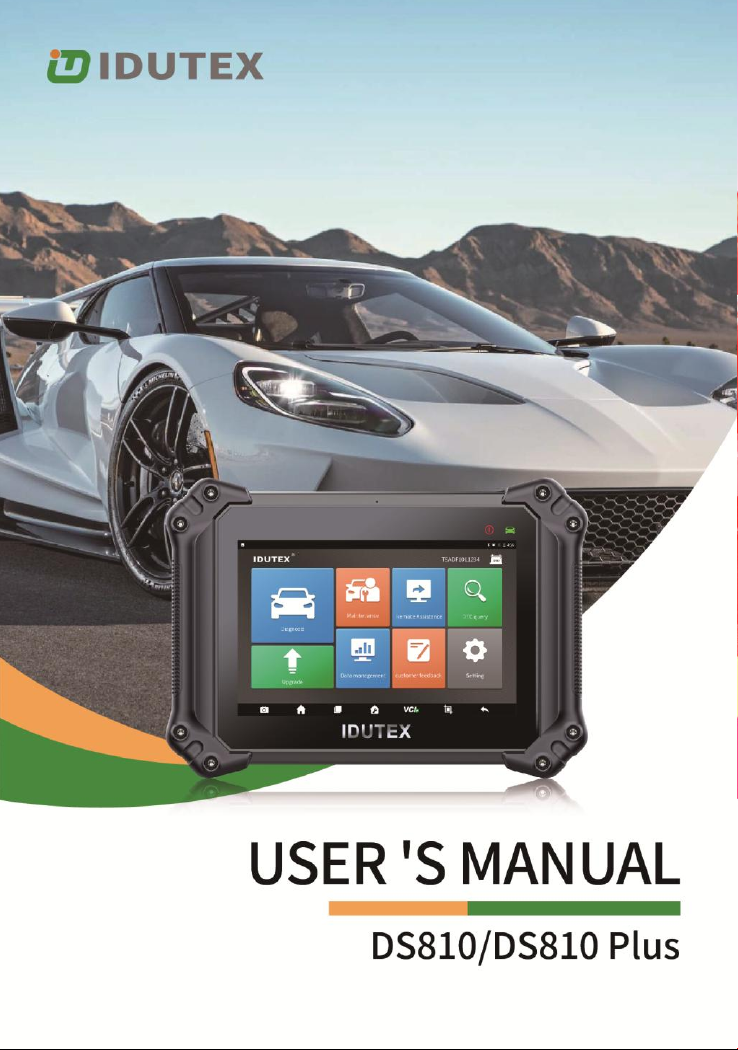


Table of Contents
1 Statement.............................................................................................. 1
1.1 Agreement................................................................................... 1
1.2 Copyright information ................................................................. 1
1.3 Disclaimer.................................................................................... 2
1.4 Safety Information....................................................................... 2
1.4.1 Inspection Precautions ..................................................... 3
2 Product description ............................................................................. 6
2.1 Product Overview ........................................................................ 6
2.2 Differences of DS810 & DS810 Plus............................................. 7
2.3 VCI Model for DS810 ................................................................... 9
2.4 VCI Model for DS810 Plus.......................................................... 11
2.5 Host Model ................................................................................ 14
2.6 The Product Specifications ........................................................ 16
3 Product software introduction.......................................................... 18
3.1 Diagnosis.................................................................................... 18
3.2 Hot function............................................................................... 22
3.3 Update ....................................................................................... 24
3.4 Data Manager............................................................................ 26
3.5 Quick Support............................................................................ 26
3.6 DTC Query.................................................................................. 27
3.7 Feedback.................................................................................... 28
3.8 Settings ...................................................................................... 29
4 Product activation.............................................................................. 33
5 Cleaning and maintenance and warranty...................................... 36
5.1 Cleaning and maintenance ........................................................ 36
5.2 Warranty.................................................................................... 37

1
1 Statement
You must carefully read the instruction manual, especially the
safety instructions, before you can connect, commission and
operate the products of IDUTEX TECHNOLOGY CO., LTD., Ltd.
(hereinafter referred to as “IDUTEX”).
1.1 Agreement
Once the product is used, it is an endorsement of the following:
(1) Please refer to the packing list of the random distribution for the
configuration equipment of this product, whichever is the actual
product;
(2) The functions and pictures described in this manual are subject
to the actual software. All information, specifications and
illustrations in the manual are the latest information at the time of
publication. The company reserves the right to change it without
notice.
1.2 Copyright information
It cannot be copied or stored in any form(electronic, mechanical,
photocopying, recording or otherwise) without prior written
permission being secured from IDUTEX. Software and data are
owned by technology and protected by copyright laws, international

2
contract law, and other national laws. It is strictly forbidden to copy
or transfer the data and software or some of the contents. If there is
any violation, the technology will be held legally responsible
according to law.
1.3 Disclaimer
(1) This manual only provides the operation and operation methods
for DS810 / DS810 Plus. The company does not assume any
responsibility for the consequences caused by using the operation
methods for other equipment operations.
(2) The company shall not accept any responsibility for accidents
caused either by the user personally or anyone else, or costs and
expenses due to equipment damages including equipment loss
caused by the user’s abuse or misuse, arbitrary changes or repairs
or operation of the equipment in a manner not in accordance with
the manual requirements.
1.4 Safety Information
For the safety of yourself and others, and to avoid damage to
equipment and vehicles, all personnel handling the equipment must
read the safety precautions mentioned in the manual.

3
1.4.1 Inspection Precautions
(1) DS810 / DS810 Plus can only be connected to a safety outlet
that is grounded. Before connecting, check and confirm that the
diagnostic circuit is in good condition. Otherwise, it is not necessary
to test to avoid damage to the main unit. If necessary, use a
multimeter to measure the diagnostic seat voltage.
(2) Use only the power cord supplied with the IDUTEX diagnostics
or detected power line.
(3) Pay special attention to the effects or damage caused by
environmental factors such as acid and alkali, poison gas, and
heavy pressure.
(4) Exhaust gases from the engine contain a variety of toxic
compounds and should be avoided. Park the vehicle in a well
ventilated area before operation.
(5) Do not place the device on the vehicle's power distribution unit.
Strong electromagnetic interference can cause damage to the
equipment.
(6) After the equipment is installed successfully, before starting the
engine, make sure that the parking brake is pulled and the speed
lever is placed in the neutral or parked position to avoid accidents
when the vehicle is started.
(7) When the engine is running at a high temperature, avoid contact

4
with high temperature components such as the water tank and the
exhaust pipe. At the same time, be careful of the voltage generated
by the components such as the ignition coil, the distributor cover,
the ignition circuit and the ignition plug during engine operation.
1.4.2 Notes on the use of the instrument
(1) This instrument is a precision electronic instrument. Do not drop
it. Handle it as gently as possible, away from heat and
electromagnetic fields.
(2) Ensure that the instrument and diagnostics are well connected
so that signal interruptions do not affect the test.
(3) Use screws as much as possible when using the cables and
connectors to avoid disconnecting and damaging the connectors
when moving. Hold the front end of the connector when pulling the
connector, and avoid pulling the rear cable to avoid damage to the
diagnostic interface.
(4) When the electrical components are energized, the circuit
cannot be disconnected to prevent self-inductance, mutual
inductance and current sensors and the vehicle ECU.
(5) The operation of this instrument requires a certain basis for
vehicle inspection and maintenance, and has a certain
understanding of the electronic control system of the vehicle under
test.
1.4.3 Operating car ECU considerations
When performing diagnostic operations on a vehicle equipped with

5
a computer control system, the following should be noted:
(1) Do not place magnetic objects such as radio speakers close to
the computer, as the magnetic properties of the speakers can
damage the circuits and components in the ECU.
(2) When the ignition switch is turned on, the internal electrical
equipment of the car must not be disconnected. Due to the
self-inductance of the coil when disconnected, a high instantaneous
voltage will be generated, which will cause damage to the sensor
and ECU;
(3) When performing repairs near a computer or sensor, special
care should be taken to avoid damage to the ECU and sensor;
(4) When carrying out maintenance work on or near the
ECU-controlled digital meter, be sure to wear a metal strap with one
end clamped to the body and the other end wrapped around the
wrist;
(5) When performing welding work on a car, the ECU system power
should be turned off beforehand;
(6) Do not use test lights to test ECU-related electrical devices to
prevent damage to the ECU or sensor unless specifically stated;
(7) Test ECU and sensors cannot be tested with a pointer-type
ohmmeter, unless otherwise specified in the test procedure, but
should be tested with a high-impedance digital meter.

6
2 Product description
2.1 Product Overview
DS810 / DS810 Plus is a proffessional efficient and convenient
diagnistic tool for passenger car.
Powerful quad-core Cortex-A53 2.0GHz processor with faster
2GB LPDDR4 and reliable 32GB On-board memory
Android 10.0 OS running on 8.0 inch IPS Multi-touch
capacitive touch screen
Unique ergonomic design with rubberized outer protection and
a rugged internal housing
Built-in rechargeable lithium-polymer battery for up to 10 hours
of continuous operation
OE-Level full-systems coverage for more than 80 vehicle
makes
Supporting 15(DS810) / 25(DS810 Plus) most commonly used
service Reset Functions, more to cover soon
Remote Technical Support via Teamviewer
11 OBDI connectors for old vehicle model for DS810 Plus

7
2.2 Differences of DS810 & DS810 Plus
Differences
DS810
DS810 Plus
VCI
Small VCI
Big VCI
Connector
OBDII
OBDII + 11 OBD1
Connectors
Service Reset Function
15
25
Service Reset Function
DS810
DS810 Plus
OILREST
X
X
ABS BLEEDING
X
X
BATTERY
X
X
DPF
X
X
EPB
X
X
INJECTOR
X
X
SAS
X
X
THROTTLE
X
X
TPMS
X
X
IMMOKEYS
X
X
AT SETTING
X
X
GEAR
X
X
HEADLIGHT
X
X
SUSPENSION
X
X
SUNROOF
X
X
A/F SET
X

8
DOOR&WINDOWS
X
LANGUAGE
X
NOX SET
X
PUMP START
X
SEAT SET
X
START&STOP
X
TIRE SET
X
TRANSPORT
X
UREA SET
X
11 OBD1 Connectors for DS810 Plus:
BMW-20
BENZ-14
GM/DAEWOO-12
KIA-20
MAZDA-17
NISSAN-14
FIAT-3
HONDA-3
VW/AUDI -2+2
MITSUBISHI HYUNDAI -12+16
Chrysler -12+8
9
2.3 VCI Model for DS810
No.
Name
Description
①
Power and
Bluetooth
connection
Indicator
Light on red & blue flashing: Power on and
Bluetooth is disconnected
Light on blue: Bluetooth is connected
Light on blue flashing: communicating

10
VCI Box Parameters
Processor
ARM 32-bit Cortex processor
Input Voltage
DC 8-30V
Operating Temperature
-10 to 70℃(14-158℉),relative
Humidity:<90%
Storage Temperature
-30 to 120℃(-22-248℉),relative
Humidity:<90%
Communication model
Bluetooth or USB
Protocols
ISO 9141, ISO14230, ISO15765,
ISO11898, SAE-J1850 VPW, SAE-1850
PWM, UDS, K/L lines, High speed CAN,
Middle speed CAN, Low speed CAN and
Single wire CAN

11
2.4 VCI Model for DS810 Plus
No.
Name
Description
①
Power Indicator
Lights up when powered(connected
to the car)
②
Vehicle
communication
indicator
Flashing When communicating
③
Bluetooth indicator
Lights up when connected to tablet
④
USB indicator
Lights up when connected to tablet

12
No.
Name
Description
⑤
USB interface
Used for wired communication with
tablets
⑥
DC interface
Power supply
No.
Name
Description
⑦
Main cable
interface
Connect the OBDII main cable

13
VCI Box Parameters
Processor
ARM 32-bit Cortex processor
Input Voltage
DC 8-30V
Operating Temperature
-10 to 70℃(14-158℉),relative
Humidity:<90%
Storage Temperature
-30 to 120℃(-22-248℉),relative
Humidity:<90%
Communication model
Bluetooth or USB
Protocols
ISO 9141, ISO14230, ISO15765,
ISO11898, SAE-J1850 VPW, SAE-1850
PWM, J1939, J1708, UDS, K/L lines,
High speed CAN, Middle speed CAN,
Low speed CAN and Single wire CAN

14
2.5 Host Model
2.3-1 The front of host
No.
Name
Description
①
Power Indicator
Lights on green when power on and the
battery is higher than 20%
Lights on red when power on and the
battery is lower than 20%
Lights on blue when it is charging
Lights on green when it is full charge
②
Communicaiton
Indicator
The light flashing when diagnose
communication

15
2.3-2 The top of host
No.
Name
Description
③
DC Port
DC power supply input port
④
USB Port
USB Port
⑤
TF Port
TF card port, Up to 32GB expand
⑥
Type-C Port
Type-C port
⑦
HDMI Port
High-Definition multimedia interface port
⑧
Start Button
The button turn ON/OFF the system
16
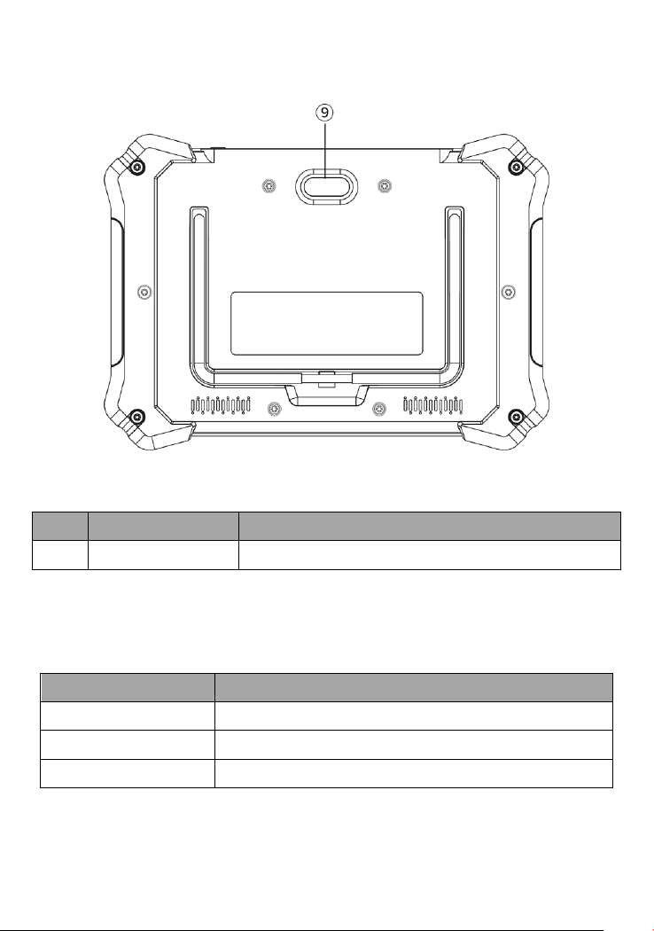
2.3-3 The back of host
No.
Name
Description
⑨
Camera
Camera lens and camera flash
2.6 The Product Specifications
Item
Description
CPU
Quad-core Cortex-A53 2.0GHz
GPU
G52 3EE MC1@800MHz
Operaton system
Android 10. 0

17
ROM
32 GB EMMC
RAM
2G LPDDR4
Display
8.0 inch IPS Multi-touch Capacitive Touch Screen
with 800*1280 resolution
Camera(rear)
5.0 Megapixel, AF with Flashlight
Connectivity
WIFI: 802.11 b/g/n/ac Support Hot spot/ 2.4/5GHz
BlueTooth 5.0, USB 2.0, Type-C
HDMI: 1080P Output
TF Card (Support up to 32GB)
Audio
Microphone
Dual Speakers
Power and Battery
8000 mAh 3.7 V lithium-polymer battery
Input Voltage
8V –30V
Power Consumption
6.5 W
Operating Temp.
-10 to 50°C (14 to 122°F)
Storage Temp.
-20 to 60°C (-4 to 140°F)
Dimensions(WxHxD)
270 mm(10.63 in) x 193 mm(7.60 in) x 38
mm(1.50 in)
Weight
NW: 1.20 kg (2.65 lb) GW: 3.00 kg (6.61 lb)
Protocols
ISO 9141-2, ISO 14230-2, ISO 15765-4, K/L-Line,
SAE-J1850 VPW, SAE-J1850 PWM, CAN ISO 11898,
Highspeed, Middlespeed, Lowspeed and
Singlespeed CAN, GM UART, UART Echo Byte
Protocol, Honda Diag-H Protocol, TP2.0, TP1.6,
SAE J1939, SAE J1708, Fault-Tolerant CAN etc.
This manual suits for next models
1
Table of contents
Other Idutex Diagnostic Equipment manuals


