Shinkawa VM-13V1 User manual

MANUAL NO.29361E1.6
Published in Nov. 1993
Revised in Aug. 2012
MODEL VM-13V1
Vector Monitor
INSTRUCTION MANUAL

FOREWORD VM-13V1
-i-
Thank you for using our Model VM-13V1 Vector Monitor.
The Model VM-13V1 Vector Monitor Instruction Manual contains descriptive information, specifications,
operation, field wiring, set and adjust procedures, and troubleshooting,.
Please study contents of this manual and related manuals thoroughly before installing or operating equipment.
! IMPORTANT NOTICE
•Before applying power to this monitor, ensure power is proper voltage for the system.
•Before operating this monitor, ensure each function switch is set to proper position.
•Do not remove / insert the internal board unless required. If internal adjustment is required,
securely support the pulled internal board to prevent falling off.
•Since electro-sensitive parts are on the internal board, care should be taken when handling
and adjusting.
Do not adjust internal switches and / or potentiometers unless required.
•This unit is designed for use by specialists or persons thoroughly familiar with the field.
•Make sure that the end user receives the Instruction Manual delivered with this unit.
Before Use.....
When the unit is delivered, inspect it for damage suffered in transport and check whether it is the item you
ordered. In the unlikely event that it was damaged in transport or does not function according to specification,
please contact the SHINKAWA Office or dealer nearest you.
Store the unit under the ambient conditions given in the specification. Avoid places where it is exposed to
high humidity or corrosive gases.

CONTENTS VM-13V1
-ii-
FORWORD
1. GENERAL INFORMATION
1-1 GENERAL··················································································································· 1
1-2 COMPOSITION··········································································································· 2
2. SPECIFICATIONS
·························································································································· 3
3. OUTLINE DRAWING
························································································································· 5
4. DESCRIOPTION OF EACH SECTION
4-1 FRONT PANEL··········································································································· 6
4-2 REAR PANEL ············································································································· 9
4-3 INTERNAL BOARD····································································································· 11
5. FAULT DISPLAY
5-1 FAULT DISPLAY STATE···························································································· 18
6. CALIBRATION
6-1 VELOCITY TRANSDUCER SENSITIVITY CALIBRATION········································· 19
6-2 DISPLAY AND OUTPUT CALIBRATION···································································· 20
6-3 CALIBRATION POINT LOCATION (INTERNAL BOARD LEFT SIDE) ······················· 21
6-4 CALIBRATION POINT LOCATION (INTERNAL BOARD RIGHT SIDE)····················· 22
7. MAINTENANCE
7-1 REPLACEMENT OF ALUMINUM ELECTROLYTIC CAPACITOR ···························· 23
8. TROUBLESHOOTING
·························································································································24
9. INPUT SIDE WIRING DIAGRAM
·························································································································· 25

1. GENERAL INFORMATION VM-13V1
-1-
1-1 GENERAL MODEL VM-13V1 Vector Monitor continuously measures the vibration vector
(amplitude/ phase angle). The VM-13V1 accepts the phase reference signal (1 pulse/
revolution) and the vibration inputs and indicates the vector data (amplitude/ phase
angle) of the selected vibration channel and rotating speed on front panel LED
displays. The recorder signal outputs of each data are available on front panel panel
BNCs and rear panel terminals.
A0
A
φ
VIBRATION
SIGNAL
BAND-PASS
OUTPUT
90°
0°
180°
270°
A
φ
GAIN
RPM
B.P.F
TRACKING
FIG.1.1
ROTOR PHASE REF.
APPLICATION EXAMPLE FOR LARGE TURBINE GENERATOR
3500
3
5
SPEED DETECTOR
PULSE/ REVOLUTION
VIBRATION MONITOR
(VM SERIES)
VIBRATION
DETECTOR
BODE PLOT
NYQUIST DIAGRAM
FREQUENCY ANALYSIS
DC OUT
3
5
FIG.1.2
VIBRATION SENSOR
VIBRATION SENSOR
PHASE REF. SENSOR
ROTOR
PHASE REF. SENSOR
VIBRATION SENSOR
RPM
O/A-AMP
F-AMP
X
Y
PHASE

1. GENERAL INFORMATION VM-13V1
-2-
1-2 COMPOSITION As shown in Fig.1.3, the VM-13V1 consisits of the following sections.
a) REFERENCE section
Generates the reference signal for filtering processing by the input of the
phase reference signal (1P/R).
b) FILTER section
Accepting the vibration input and the signal from the reference part,
processes the vector computation. (Includng the sensitivity and range
adjustment of the input transducer.)
Overall Amplitude
Filtered Amplitude
VM-13V1
VECTOR
MOONITOR
rpm
Phase Angle
X (REAL)
Y (IMAG)
Filtered AC
1
2
11
AUX
1 P/R
AUX
Vibration
Signal Input
Phase
Reference
Signal Input
DC Recorder Output
FIG.1.4
FIG.1.3
BAND WIDTH
CONT
PLL
MULTI. SYNC.
REF. GEN
N. SETL
PHASE
DETECT.
XTAL
OSC
D / A
88888 RPM
REVOLUTION
RPM_DC
D / A
888
PHAASE
DEG
PHASE_DC
UNIT
SEL.
A / D
888
AMPLITUDE
mils
m/m
mils
m/m
DUAL
RESOLVER :
DUAL
RESOLVER : X
1N / 2N
Y
X
ADDER.
DEGICH.
X2+Y 2
P-P
DETECT O / A Amp・DC
FILTERD Amp・DC
X (REAL)
Y (IMAG) DC
FILTER SECTION
O / A FILTERD
FILTERD ・
REFERENCE SECTION
AUTO TRIG
MAN. TRIG
Integration
EDDY
VEL.
AUTO
MAN.
NORM
AUX
1~11CH
AUX
VIB. SIG
1P/R SIG
TRIG.
LEVE
VM-13V1 VECTOR MONITOR BLOCK DIAGRAM
RANGGAIN
・
・
・
・

2. SPECIFICATIONS VM-13V1
-3-
1. RPM RANGE 200 to 100,000rpm
2. DISPLAY
1) RPM Readout : 5 digits LED(red), 200 to 99,999rpm
Accuracy : ±(0.003% of rdg.+1 digit) at 25°C
Resolution : 1rpm
2) AMPLITUDE Readout : 3 digits LED(red)
Full Scale Range : 500/250/125µm P-P
20.0/10.0/5.0mils P-P
Unit(µm or mils)selection:Selected by internal switch
Range selection:Selected by front panel switch
Accuracy : Overall ±3% of F.S. at 25°C
Filtered ±3% of F.S. at 25°C
Resolution : 1µm or 0.1mils
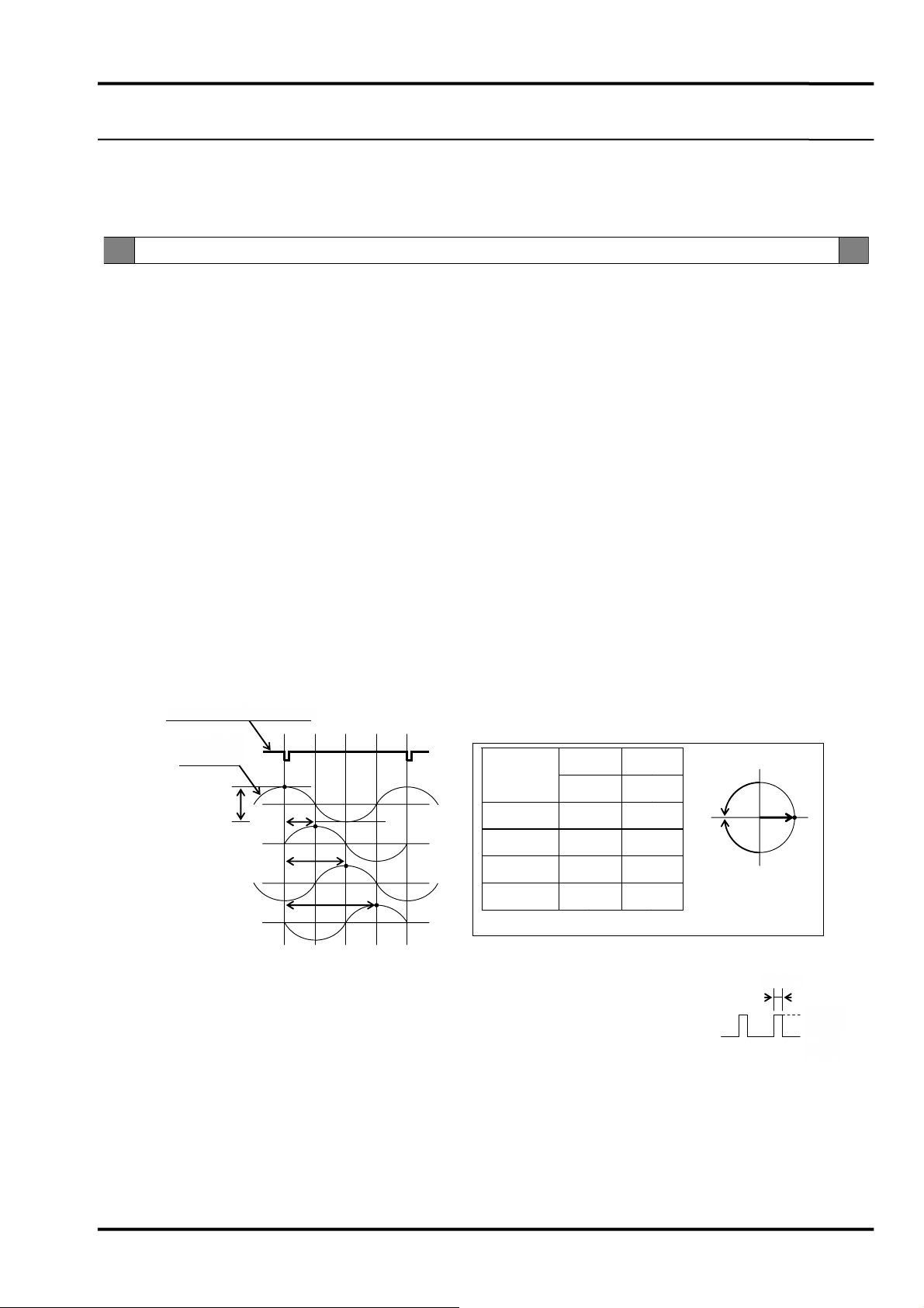
3) PHASE ANGLE Readout : 3 digits LED(red), 0 to 360°
Operating Range : 200 to 100,000rpm
Resolution : 1°
Accuracy : ±3° at at amplitude input>10% F.S. and 25°C
3. TRACKING FILTER
1) OPERATING FREQUENCY RANGE
200 to 100,000rpm(3.33 to 1,666Hz)
2) BAND WIDTH(BW) 0.2 or 2Hz(-3dB down)(selected by front panel switch)
3) BAND WIDTH SELECT MODE
AUTO or MANUAL(selected by front panel switch)
AUTO Mode : <1,000rpm=0.2Hz BW
>1,000rpm=2Hz BW
4) FILTER RESPONSE 0.2Hz BW=0.6rpm/s
2Hz BW=60rpm/s
5) ORDER RATIO 1×(1N) or 2×(2N)(selected by front panel switch)
7) DYNAMIC RANGE 60dB or more
4. INPUT SIGNAL
1) VIBRATION SIGNAL INPUT From displacement transducers or velocity transducers(selected by internal switch)
Input Impedance : 10kΩ(unbalance)
Input Sensitivity : Displacement transducer 2.5V/mm,4V/mm,5V/mm,8V/mm
(selected by internal switch)
Velocity transducer 2.5 to 40mV/mm/s
(internal potentiometer setting)
Input Channel : 1 to 11ch(rear panel screw terminal)
AUX ch(rear panel screw terminal and front panel BNC)
SPECIFICATIONS
GENERAL
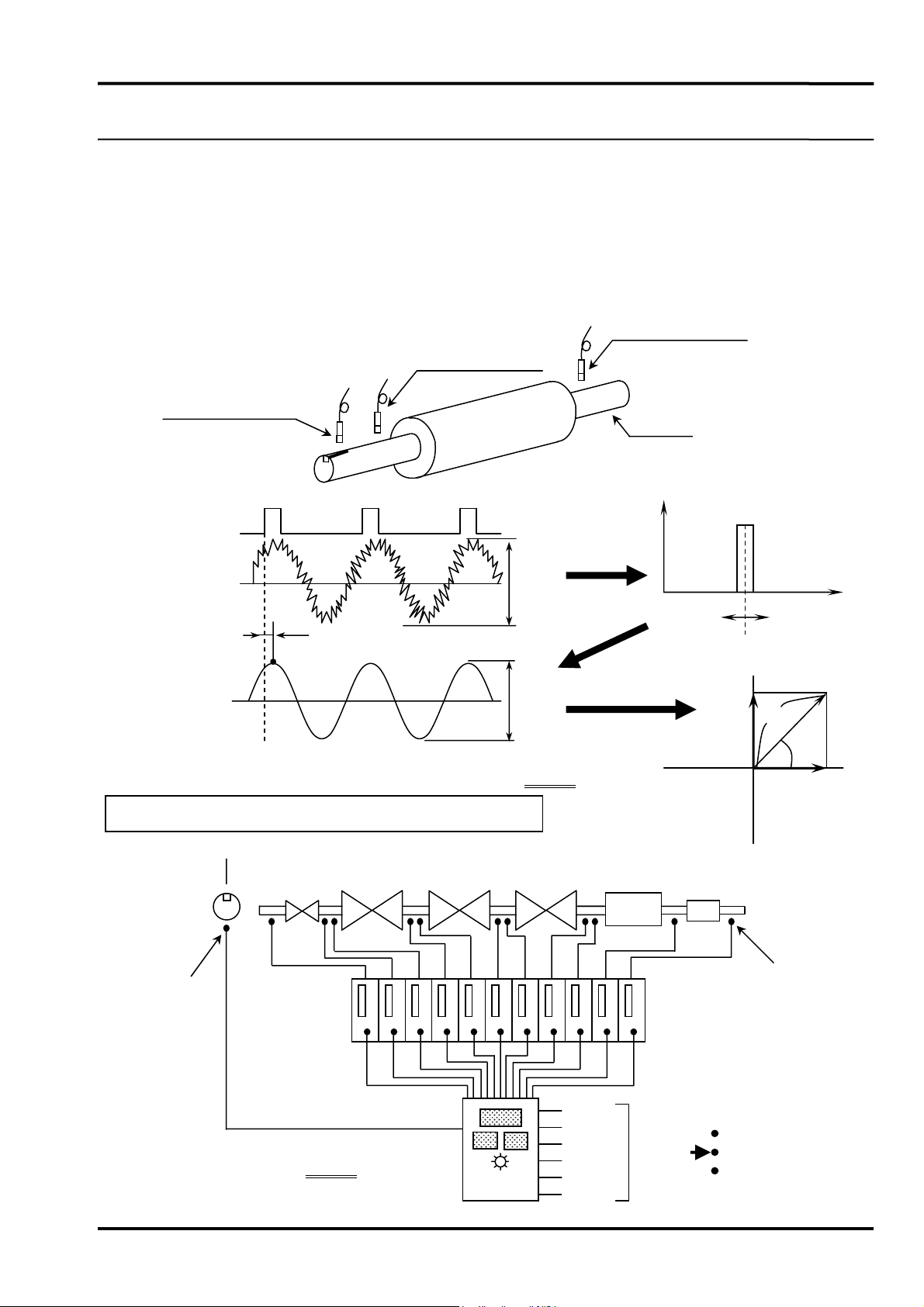
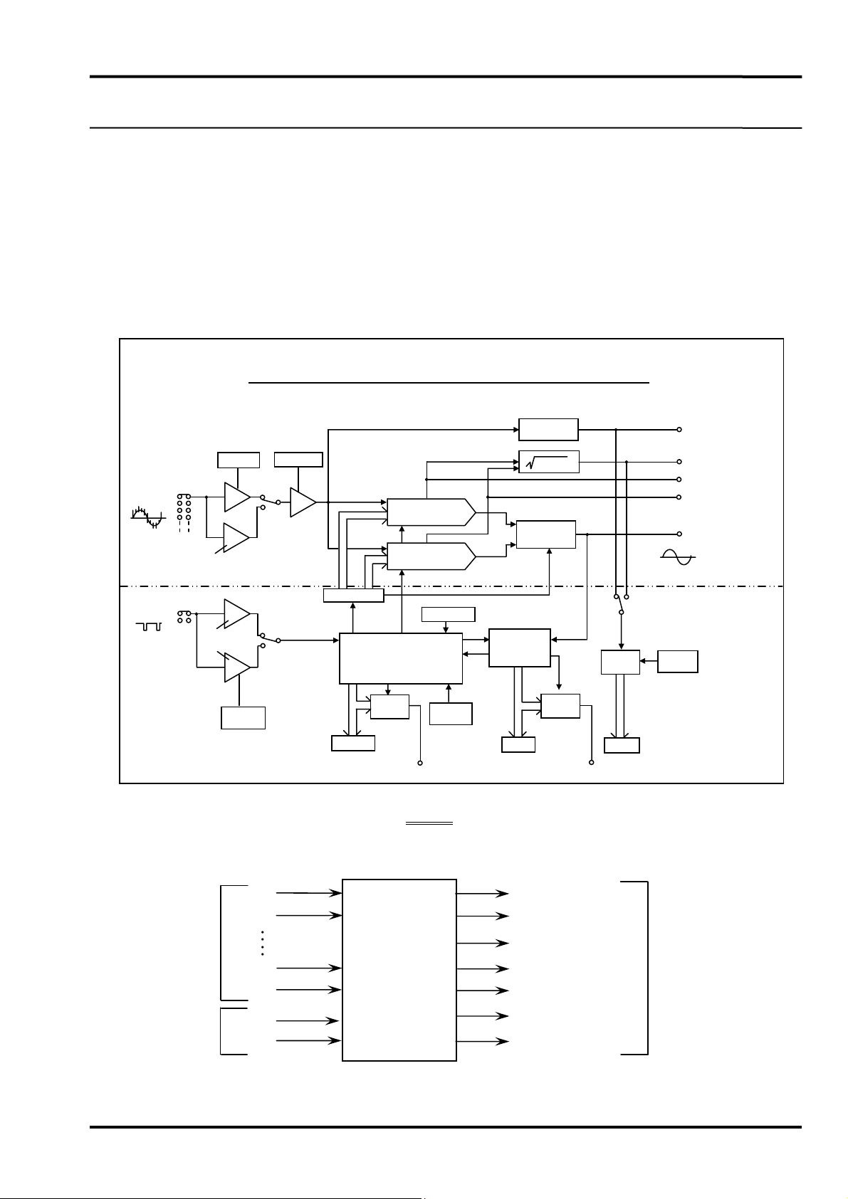
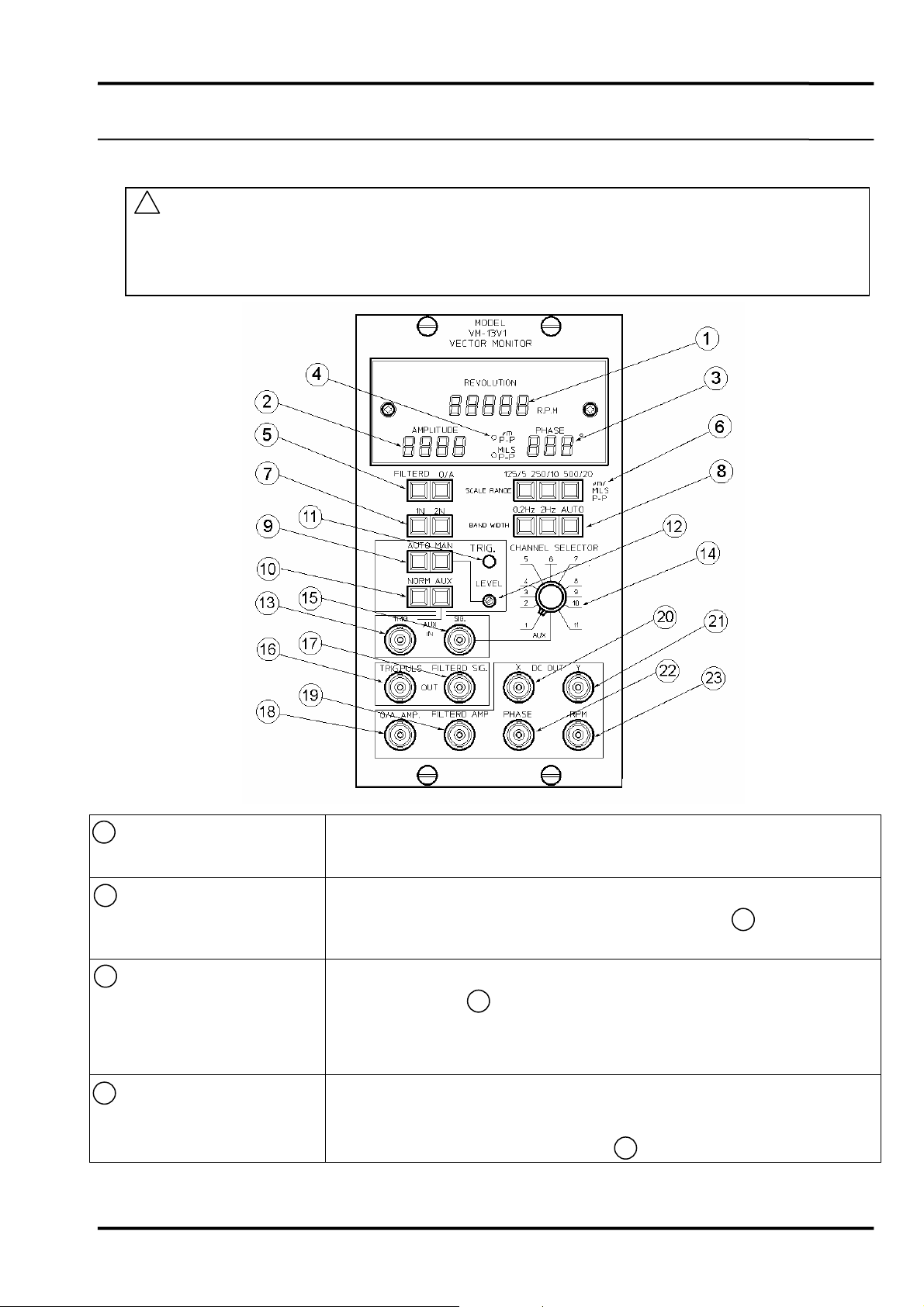
MODEL VM-13V1 VECTOR MONITOR accepts vibration transducer inputs (max.11 channels +AUX) and phase
reference signal (1 pulse per revolution). It provides a digital readout of selected vibration vector (amplitude and
phase angle) and machine speed (rpm), and recorder outputs.
VM-13V1
VECTOR
MONITOR DC Recorder Output
Filtered AC
Y(IMAGINARY)
X(REAL)
Phase Angle
Filtered Amplitude
Overall Amplitude
rpm
1
2
11
AUX
1 P/R
AUX
Vibration Signal Input
Phase Reference
Signal Input
……..
39335E1.5

2. SPECIFICATIONS VM-13V1
-4-
2) PHASE REFERENCE SIGNAL INPUT
Input Impedance : 10kΩ(unbalance)
Signal Level : 0.4 to 100V peak
Pulse Width : >10µs
Trigger Mode : AUTO or MANUAL(selected by front panel switch)
Manual Trigger Level
: -20 to +20V(front panel potentiometer setting)
Trigger Slope : Positive edge or Negative edge(selected by internal switch)
Signal Input : Normal input:Rear panel screw terminal
AUX input:Front panel BNC and rear panel screw terminal
5. RECORDER OUTPUT
1) RPM 0.2 to 10VDC/200 to 10,000rpm or
0.02 to 10VDC/200 to 100,000rpm(selected by internal switch)
Accuracy : ±3% of F.S. at 25°C
Resolution : 0.04% of F.S.
2) AMPLITUDE 0 to 10VDC/0 to full scale(overall/filtered)
Accuracy : ±3% of F.S. at 25°C
3) PHASE ANGLE 0 to 3.6VDC/0 to 360°
Accuracy : ±4° amplitude input>10% F.S. at 25°C
4) X(REAL) 0 to ±10VDC
Accuracy : ±3% of F.S. at 25°C
5) Y(IMAGINARY) 0 to ±10VDC
Accuracy : ±3% of F.S. at 25°C
6) X,Y POLARITY CW(clockwise) or CCW(counter clockwise)(selected by internal switch)
7) FILTERED AC 10V P-P/F.S.
8) EACH OUTPUT IMPEDANCE 100Ω
9) EACH SIGNAL OUTPUT Front panel BNC and rear panel screw terminals
8) TRIGGER PULSE -0.5 to +0.5V(PL),4 to 5V(PH)(front panel BNC)
6. OTHERS
1) POWER SUPPLY 100VAC±10%, single phase 47 to 63Hz Approx.40VA
2) INSULATION RESISTANCE 100MΩor more at 500VDC(power - ground)
3) DIELECTRIC STRENGTH 1,500VAC, one minute (power - ground)
4) TEMPERATURE RANGE Operating temperature : 0 to 40°C
Storage temperature : -20 to +60°C
Relative humidity : 95%RH, noncondensing
5) FINISH Front plate : Munsell 5Y7/1(SPCC)
6) MASS Approx.8kg
7) ACCESSORY SUPPLIED Fuse(1.5A, 1 pce.)
SPECIFICATIONS
50µs
5V
0V
CW CCW
Phase
Angle XYXY
0° +A 0 +A 0
90° 0 -A 0 +A
180° -A 0 -A 0
270° 0 +A 0 -A
A:10V/F.S.
X
0°
Y
180°
CW
CCW
Phase reference signal
270°
180°
90°
0°
Vibration
signal
A
39335E1.5

3.OUTLINE DRAWINGVM-13V1
-5-

4. DESCRIPTION OF EACH SECTION VM-13V1
-6-
4-1 FORNT PANEL
! NOTE
This monitor provides the peak to peak rectifying circuit for O/A (overall) amplitude. Therefore,
depending on the vibration waveform, this monitor might indicate a little higher O/A amplitude
level than other average rectifying type vibration monitor installed at the same machine.
1 RPM Display 5-digit display indicating the shaft rotating speed.
Display range : 200 to 99,999rpm
2 AMPLITUDE Display 3 1/2-digit display indicating displacement amplitude in peak to peak
selected by the Vibration Input Channal Selector Switch ( 14 ).
Display range : 0 to 500µm or 0 to 19.9mils
3 PHASE Display 3-digit display indicating phase angle selected by the Vibration Input Channal
Selector Switch ( 14 ),when the VM-13V1 is operated in FILTERED mode.
Display range : 0 to 360deg.
Note) The display is blanked in O/A mode.
4 AMPL. Unit LED Iindicating the amplitude unit (µm or mils )by illuminating the corresponding
LED.
Note) For unit selection, see 4.3.5 6 on page 17.

4. DESCRIPTION OF EACH SECTION VM-13V1
-7-
5 AMPL. Mode Selector
Switch
Used to seleect the amplitude mode of operation.
FILTERED : Filtered vibration (Peak to Peak)
O/A : Overall vibration (Peak to Peak)
Note) The PHASE Display ( 3 ) is blanked in O/A mode.
6FS Range Selector Switch
Used to select full scale range of the amplitude.
Metric mode : 125µm / 250µm / 500µm
Inch mode : 5mils / 10mils / 20mils
Note) The amplitude display will be flashed when the input level
exceeds the selected full scale.
7 1N/2N Selector Switch
Used to select frequency multiplier (N), when selecting FILTERD mode by
the AMPL. Mode Selector Switch ( 5 ).
1N (1×) : 1×speed of the synchronizing signal that tunes the filter.
2N (2×) : 2×speed of the synchronizing signal that tunes the filter.
Note) When 2N is selected, the RPM display will indicate 2×(twice)
rotating speed.
8 Band Width Selector
Switch
Used to select filter band width when selecting FILTERD mode by the
AMPLMode Selector Switch ( 5 ).
0.2Hz : Band width is 0.2Hz.
2Hz : Band width is 2Hz.
AUTO : Band width is 0.2Hz below 1,000rpm.
Band width is 2Hz at 1,000rpm or more.
Note) In 0.2Hz, the response of the amplitude and phase output
(display) will become very slow.
9 Trigger Mode Selector
Switch
Used to select the trigger mode (AUTO/ MANUAL) for the reference input
signal (1P/R). In the manual (MAN.) mode, the threshold level should be
adjusted by the LEVEL potentiometer ( 12 ).
10 Trigger Input Selector
Switch
Used to select the trigfer signal source.
NORM : Input from the rear 1P/R NORM terminals.
AUX : Input from the rear 1P/R AUX terminals or the front panel
AUX IN TRIG. connector ( 13 ).
Note) If the external sweep operation is required for ferquency
analysis, etc.,connect the external oscillator to the rear 1P/R
AUX
terminals or the front panel AUX IN TRIG. connector
11 Trigger LED Yellow LED that is on when trigger pulse is input.
12 Trigger Level
Potentiomenter
Used to adjust trigger threshold level in the manual trigger mode.
(Reger to 9 above.)

4. DESCRIPTION OF EACH SECTION VM-13V1
-8-
13 AUX Trigger Input
Connector
BNC connector to provide auxiliary trigger input. Refer to 10 on page 7.
Note) For Trigger slope and hysteresis setting, see 4.3.5 1 , 5 on
page 15 and 16.
14 Vibration Channel Selector
Switch
Selects one of up to eleven vibration input and AUX input. When AUX is
selected, vibration signal can be input directiy from AUX Vibration Input
Connector( 15 ) below.。
15 AUX Vibration Input
Connector
BNC connector to provide auxiliary vibration input.
16 Trigger Pulse Output
Connector
BNC connector to provide trigger pulse output.
(TTL compatible level)
17 Filtered Vibration Signal
Output Connector
BNC connector to provide filtered vibration signal output.
(10Vp-p/FS)
18 Overall Amplitude Signal
Output Connector
BNC connector to provide overall amplitude signal output.
(0 to 10VDC/FS)
19 Filtered Amplitude Signal
Output Connector
BNC connector to provide filtered amplitude signal output.
(0 to 10VDC/FS)
20 X (REAL) Output
Connector
BNC connector to provide X (real) component signal output.
(0 to ±10VDC/FS)
21 Y (IMAG) Output
Connector
BNC connector to provide Y (imaginary) component signal output.
(0 to ±10VDC/FS)
Note) For X,Y output rotation (CW/CCW) selection, see
4.3.5 6 on page 15.
22 Phase DC Output
Connector
BNC connector to provide phase angel signal output.
(0 to +3.6V/ 0 to 360 deg.)
23 RPM DC Output Connector BNC connector to provide RPM signal output.
(0.2 to 10VDC/ 200 to 10,000rpm or 0.02 to 10VDC/ 200 to 100,000rpm)
Note) For RPM full scale selection (10,000 or 100,000rpm), see 4.3.5
2 on page 15.
! Note
Make sure to insulate the output of each connector against earth.
5V
0
Approx.50µs

4. DESCRIPTION OF EACH SECTION VM-13V1
-9-
4-2 REAR PANEL
1 Signal Input Terminal Block MEAS. 1ch to 11ch, AUX :
Input terminals for up to 11 separate vibration signals and one auxiliary
vibration signal.
•Connect vibration signals from vibration transducer or vibration
monitor (VM Series) “MONITOR” output.
•AUX terminals is parallel connection to the front panel AUX
Vibration Input Connrctor. (See 4.1 15 on page 8.)
•Connect signal common to COM treminal indepemdently for each
channel.
1P/R, NORM, AUX : Input terminal for one (normal) reference signal and
one auxiliary refernce signal.
•Connect 1P/R signals from phase marker transducer or Phase Marker
(VM-5P) “MONITOR” output.
•AUX terminlas is parallel connector to the front panel AUX Trigger
Input Connector. (See 4.1 13 on page 8.)
•Connect signal common to COM terminal independently for each
channel.
VIBRATION SIGNAL INPUTS
1CH
2CH
NORMA
(AUX)
11CH
(AUX)
! WARNING
Beware of electric shock
from high-voltage parts.
REFERENCE SIGNAL INPUTS

4. DESCRIPTION OF EACH SECTION VM-13V1
-10-
2 Signal Output terminal Block
1) O/A AMP DC
2) FILTERD AMP DC
3) PHASE DC
4) RPM DC
5) X
6) Y
7) FILTRD AC
•All outputs on this terminal block are parallel connections to the
corresponding front panel output connectors.(See 4.1 17 to 23 on page 9.)
Provides overall amplitude signal output. (0 to 10VDC / FS)
Provides filtered amplitude signal output. (10Vp-p / FS)
Provides phase angle signal output. (0 to +3.6V /0 to 360 deg.)
Porvides RPM signal output.
(0.2 to 10VDC / 200 to 10,000rpm or 0.02 to 10VDC / 200 to 100,000rpm)
Provides X (REAL) component signal output. (0 to ±10VDC / FS)
Provides Y (IMAGINARY) component signal output. (0 to ±10VDC / FS)
Provides filtered vibration signal output. (0 to 10VDC / FS)
Note)
( Terminal screw ldentification
Upper Screw →Signal
Lower Screw →Signal Common
( Connect signal common to COM terminal independently
for each channel.
3 Power Supply Switch (Lock type)
4 Fuse Holder A fuse of 1.5A is inserted.
Note) If the fuse blows, check the cause of blowing and take
corrective action. After this, install a new fuse with the
same rating.
5 Power Supply Input
Terminal Block
1) AC-AC
2) F.G
Used for connections of power supply input.
Note) Before applying power, ensure power is proper voltage
(100VAC ±10%)
Flame Ground terminals.
Note) •Connect to proper earth.
•The terminals are disconnected to the internal COM by
means of the capacitor.
F.G
C
F.G
INTERNAL COM
O/A
DC
H
L(COM)
Ex.)

4. DESCRIPTION OF EACH SECTION VM-13V1
-11-
4-3 INTERNAL BOARD
4-3-1 INTERNAL BOARD WITHDRAWAL
1) Slowly Loosen four setscrews on the upper and lower sides equally.
(At fixing, tighten four setscrews equally in the same way.)
Note) If excessive force is applied, the screw thread could be
damaged.
2) Hold the diagonal two setscrews with fingers and slowly pull out the internal
board.
Note) When it is required to completey pull out the internal board,
support the internal board as shown below.(Slide-lock spring is
not attached to this monitor.)
*
*
*
*

4. DESCRIPTION OF EACH SECTION VM-13V1
-12-
CAUTION
Pulling out the internal board obliquely or to the excessive extent may result in
twisted flat cable.
Twisted flat cable cannot be housed properly in the cable case.
Insertion of the internal chassis without flat cable housed properly in the cable
case could cause troubles.
Cable is twisted.

4. DESCRIPTION OF EACH SECTION VM-13V1
-13-
4-3-2 INTERNAL BOARD TOP VIEW
TRIGGER SLOPE
POSITIVE
EDGE
NEGATIVE
ROTATION
CCW
CW
10000rpm
F.S
100000rpm
PRM.DC
SENSOR SELECT
VAR GAIN
ADJ
2.5~10
VAR
10~40
VAR
VEL
FIX.
VELOCITY
EDDY
10000rpm/FS ∗
100000rpm/FS
POSITIVE
NEGATIVE ∗
TRIGGER SLOPE
SELECTOR SW
DC OUTPUT F.S.
SELECTOR SW
X,Y OUTPUT ROTATION SW
CCW (Counter clockwise)
∗
CW (Clockwise)
VIBRATION TRANSDUCER
SELECTTION
3
4
1
2
a
b
c
d
∗
Installed prior to shipment.
VEL. SENS. ADJ. POTENTIOMETER
2.5 to 10mV/mm/sec
10 to 40mV/mm/sec
VARIABLE SEMS. MODE
FIXED SENS. MODE (8mV/mm/sec)
VELOCITY TRANSDUCER
EDDY CURRENT TRANSDUCER∗
a
b
c
d

4. DESCRIPTION OF EACH SECTION VM-13V1
-14-
4-3-3 INTERNAL BOARD SIDE VIEW (LEFT SIDE)
4-3-4 INTERNAL BOARD SIDE VIEW (RIGHT SIDE)
POSI.EDGE NEG.EDGE
TRIG SLOPE
SELECT
ZERO ADJ
rpm DC
F.S ADJ
rm
p
DC 10000rm
p
/FS
HYST.SET
2.0V
1.5V
1.0V
0.5V
UNIT_SELECTOR M/M MILS PHASE_DC
F.S ADJ ZERO ADJ
*
TRIG. HYST.
SET JUMPER
AMPLITUDE UNIT
SELECTOR SW
6
5
*Installed prior to shipment.
EDDY VEL FIX VAR 10~40 2.5~10VAR_GAIN_ADJ
2.5V/mm
4V/mm
5V/mm
8V/mm
SENSOR_TYPE
SELECT
*
F.S_SET_SW
EDDY CURRENT TRANSDUCER
SENS. SELECTOR SW
7
CW CCW
ROTATION POLALYTY
* Installed prior to shipment.

4. DESCRIPTION OF EACH SECTION VM-13V1
-15-
4-3-5 FUNCTIONAL DESCRIPTIONS
1 Trigger Slope Selector SW Used to select trigger slope (POSITIVE or NEGATIVE lead edge).
Note) In order to be compatible with Model VK series Transducer,
the trigger slope mode is set to NEGATIVE prior to
shipment.
2 PRM DC Output F.S. Selector
SW
Used to select RPM DC output full scale (0.2V to 10V / 200 to 10,000rpm
or 0.02V to 10V / 200 to 100,000rpm).
Note) It is set to 0.2V to 10V / 200 to 10,000rmp prior to shipment.
3 X,Y Output Rotation SW Used to select X,Y output rotation (CW – clockwise or CCW – counter
clockwise).
CW CCW
PHASE
ANGLE X Y X Y
0° +A 0+A 0
90° 0 -A 0 +A
180° -A 0-A 0
270° 0 +A 0 -A
A:10V/F.S.
PHASE REFERNCE SIGNAL
270°
180°
90°
0°
VIBRATION SIGNAL
A
X
0°
Y
180°
CW
CCW
A

4. DESCRIPTION OF EACH SECTION VM-13V1
-16-
4 Vibration Transducer
Selection
a Transducer Selector SW
b Vel. Sens. Mode
Selector SW
c Vel. Var. Sens. Range
Selector SW
d Vel. Sens. Adj.
Potentiometer
Eddy current or velocity type vibration transducer can be connected to this
monitor.
Note) 1. Intrgration circuit is incoroprated so that peak to peak
amplitude level is output even if the velocity transducer is
used.
2. It is impossible to use both types of transducers at same
time.
Used to select the input transducer type (EDDY current trnasducer or
VELOCITY transducer).
Note) It is set to EDDY current transducer prior to shipment.
Used to select the velocity transducer sensitivity mode below.
FIX : 8mV/mm/sec 0 to peak (fixed)
VAR. VEL : 2.5 to 40mV/mm/sec 0 to peak
Used to select the sensitivity range when the VAR.
VEL mode above is selected.
2.5~10 : 2.5~10mV/mm/sec 0 to peak
10~40 : 10~40mV/mm/sec 0 to peak
Used to adjust the velocity transducer sensitvity within the range of c .
(15 turns)
Note) 1. It is set to 8mV/mm/sec 0 to peak prior to shipment.
2. For adjustment procedure, see 6.1 on page 19.
5 Trig. Hyst. Set Jumper
Used to set the trigger hysteresis (0.5, 1.0, 1.5, or 2.0V). If improper
triggering occurs due to noise, etc., increase hysteresis to prevent triggering
problem as shown below.
Note) It is set to 0.5V prior to shipment.
To change hysterersis,reinstall the jumper pin into the
desired.position.
PHASE REFERENCE
1P/R INPUT SIGNAL
TRIGGER PULSE
•
(IMPROPERLY ADJUSTED) (PROPERLY ADJUSTED)
THRESHOLD LEVEL
HYSTERESIS
HYSTERESIS ADJUSTMENT

4. DESCRIPTION OF EACH SECTION VM-13V1
-17-
6 AMPL. Unit Selector SW Used to select the amplitude unit (µm or mils) for the Amplitude Dispiay
(4-1 2 on page 6).
Note) It is set to µm unit prior to shipment.
7 Eddy Current Transducer
Sens. Selector SW
Used to select the eddy current transducer sensitivity (2.5,4,5,8V/mm).
Note) It is set to 8V/mm sensitivity prior to shipment.
Table of contents
Popular Diagnostic Equipment manuals by other brands

VibroSystM
VibroSystM PCS-200ESB installation manual

Wow
Wow iQ 150 quick start guide

Xtool
Xtool Nitro LT quick start guide

Shimadzu
Shimadzu Sonialvision Safire Operation guide

Parker Research Corp
Parker Research Corp DA1500DR operating instructions

BioVision Technologies
BioVision Technologies CMAR-01 quick start guide

Primes
Primes MicroSpotMonitor Plus HighBrilliance Original instructions

Midtronics
Midtronics GR8-1250 instruction manual

Enovation Controls
Enovation Controls MURPHY PowerView PV25 Installation & operation manual

Kaixin
Kaixin KX5600 user manual

Procentec
Procentec Atlas 101-800110 user manual

Hamaton
Hamaton H47 quick start guide