MAC TOOLS BSA200 User manual

24
2650-1271-00
BSA200
Operator’s Manual
Hand Held-Accuracy with a Pulsed 120 Amp Load
The BSA200 is the ultimate hand-held tester. It is the auto
industry’s answer to portability in a professionally accurate load
tester and system analyzer.
Mac Tools Inc.
505 N. Cleveland Ave.
Suite 200
Westerville, OH 43082
Phone: 1-800-MAC-TOOLS or 1-800-622-8665
Fax: 1-800-MAC-FAX5 or 1-800-622-3295

2
23
CONGRATULATIONS!
You have purchased one of MAC’s hand-held Charging System
Analyzers. It is designed to test each component of a vehicle's electrical
system with greater speed and accuracy. If you should have any
questions about your tester, testing procedures, or service see page 24
for contact information.
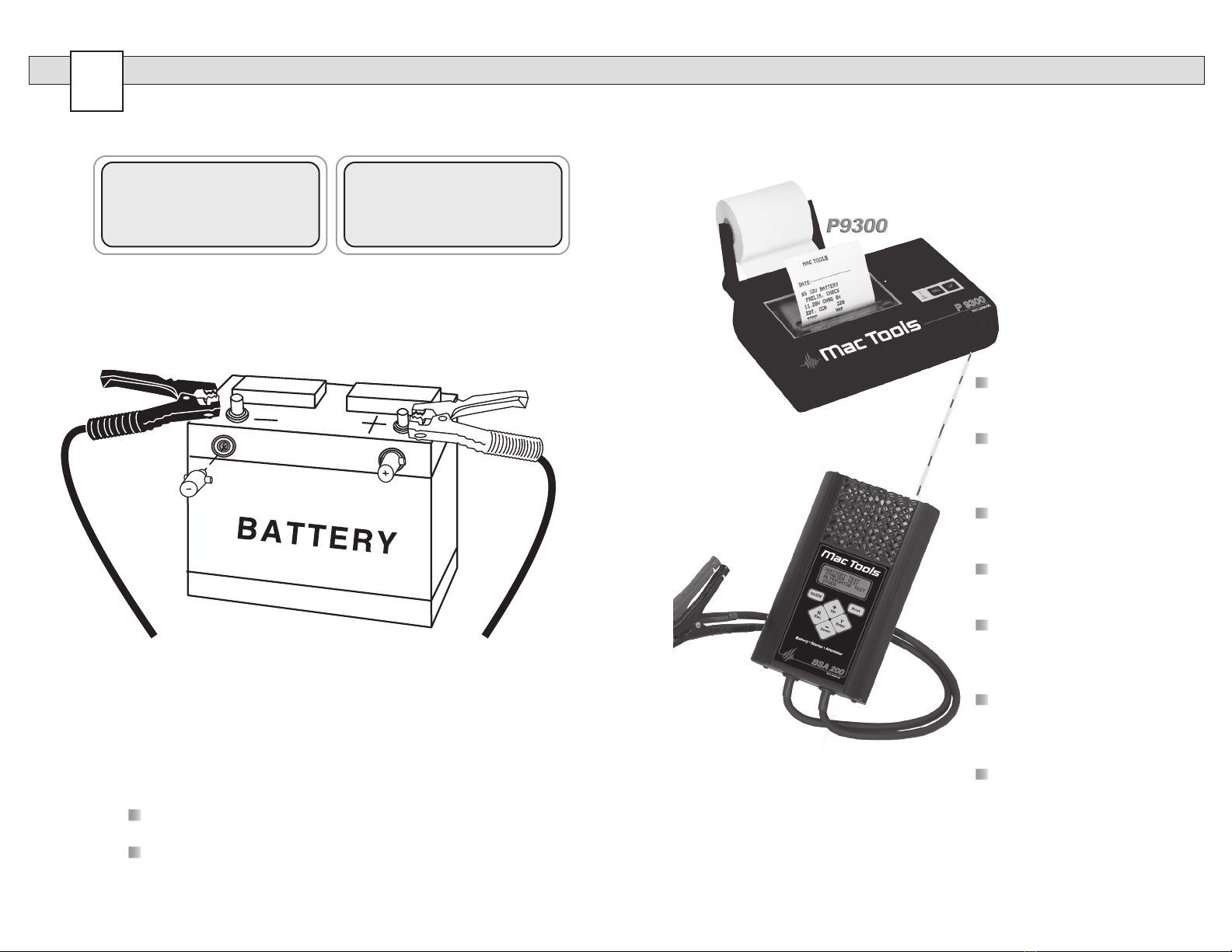
BVA 200s
Load Test Capacity..................120 Amp
Battery sizes ...........................200-1600 CCA
Digital Back-Lit Display ..........1" x 2.5" - 4 line x 16 character
Volt Ranges.............................Digital 0-30
Cooling....................................Vented
Leads ......................................Load Amp-2 1/2 ft., 6 Gauge
Size .........................................5 7/8" x 9 1/2" x 1 7/8"
Memory ...................................stores the last 200 tests
Internal Battery........................9 Volt Alkaline
Optional P9300 .......................Infrared printer and carrying case
Optional CC100 ......................BSA200 Carrying case only
Optional AC-12 ......................PC Interface adapter cord
Weight.....................................4 lbs.
What to Expect from the BSA200:
Immediately recognize a bad battery and perform a complete
charging system analysis.The BSA200 is a portable full-featured
menu-driven battery tester and charging system analyzer that provides
quick, professional load results using Advanced DIgital Pulse Load
Technology. Quick battery checks will increase charging productivity.
The BSA200 is user friendly. It tells you what to do. The stator-
diode test automatically indicates open or shorted stator-diodes. It is
professionally accurate. Detailed test results are LCD displayed after
each test or can be reviewed and/or printed from memory.
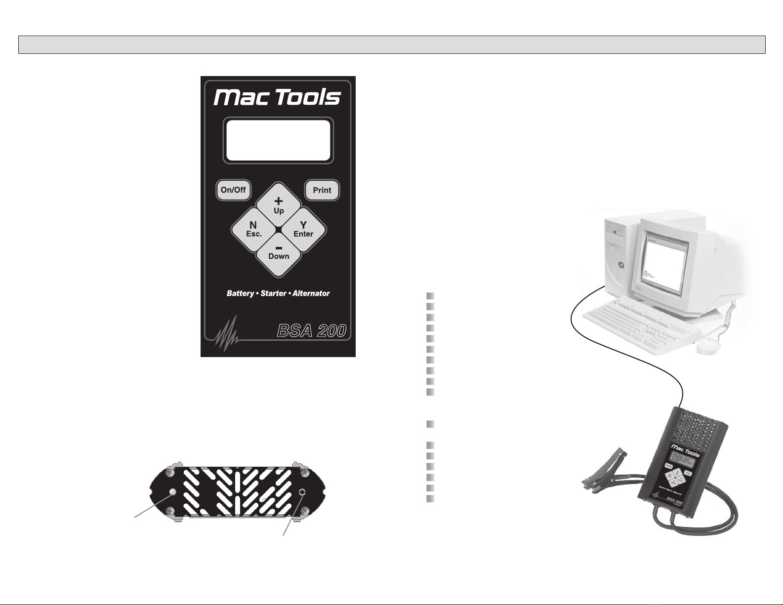
Caution: The BSA200 grill may get hot after repeated use. Be sure to
hold the unit from the side grips only. Keep hands away from the grill.
LIMITED WARRANTY
12 MONTHS FROM DATE OF PURCHASE-
CABLES 90 DAYS
The manufacturer warrants to the consumer that this product
will be free from defects in material or workmanship for
a period of twelve (12) months from the date of original
purchase.
Products that fail within this 12 month warranty period will
be repaired or replaced at the manufacturer's option to the
consumer, when determined by the manufacturer that the
product failed due to defects in material or workmanship. This
warranty is limited to the repair or replacement of parts and
the necessary labor by the manufacturer to effect the repair or
replacement of the product. In no event shall the manufacturer
be responsible for special, incidental or consequential damages
or costs incurred due to the failure of this product.
Improper use, accident, water damage, abuse, unauthorized
repairs or alterations voids this warranty. The manufacturer
disclaims any liability or consequential damages due to breach
of any written or implied warranty on its test equipment.
WARRANTY AND SERVICE INFORMATION
Warranty claims to the manufacturer's service department
must be transportation prepaid and accompanied with dated
proof of purchase. This warranty applies only to the original
purchaser and is non-transferable. Shipper damage incurred
during return shipments is not covered under this warranty. It
is the responsibility of the shipper (the customer returning the
Test Equipment) to package the tester properly to prevent any
damage during return shipment. Repair costs for such damages
will be charged back to shipper (customer returning the Test
Equipment). Protect the product By shipping in original carton
or add plenty of over-pack cushioning such as crumpled up
newspaper.
For Service Please Contact:
Auto Meter Products, Inc.
413 West Elm Street
Sycamore, IL 60178
Phone: 866-883-8378
Fax: 815-895-6786
test_service@autometer.com

22
3
TABLE OF CONTENTS
Specications -------------------------------------------------------2
Safety -----------------------------------------------------------------4
Cause of Battery Failure -----------------------------------------4
Inspection and Visual Check------------------------------------5
Controls and Functions-------------------------------------------6
Maintenance --------------------------------------------------------7
Clamp Replacement ----------------------------------------------7
Battery Replacement ---------------------------------------------7
Sections
1. Hook Up --------------------------------------------------------8
2. Battery Preliminary Check ---------------------------------9
3. Battery Load Test-------------------------------------------10
4. Starter Draw Test ------------------------------------------- 12
5. Alternator Test----------------------------------------------- 14
6. Other Menu Items
Review Tests -------------------------------------------16
Printer---------------------------------------------------- 17
Printing Test Results --------------------------------- 17
Voltmeter ------------------------------------------------ 18
Setup----------------------------------------------------- 18
PC Interface -------------------------------------------- 19
Opening Windows 98 Hyper Terminal -----------19
Downloading Test Information --------------------- 20
Capturing Information in Microsoft Excel -------21
Warranty Information--------------------------------------------23
Contact Information --------------------------------------------- 24
Note: The BSA200 checks and load tests 6 volt and 12 volt
Batteries and tests the starter and alternator on 12 volt and 24
volt systems. The following examples illustrated are for a 12 volt
system. The BSA200 automatically identies the appropriate
voltage and displays the menu selection and instructions needed
for that system.
NOTES

4
21
SAFETY
Carefully read all operating instructions
before using the BSA200
Wear eye protection when working
around batteries.
Be sure each test is completed before
removing load clamps to prevent arcing
and potential explosion from battery
gases. Never remove load clamps
while testing. Keep sparks ames, or
cigarettes away from batteries.
Keep hair, hands, and clothing as well
as tester leads and cords away from
moving blades and belts.
Provide adequate ventilation to remove car exhaust.
In extremely cold temperatures, check for frozen electrolytic uid
before applying load. Do not attempt to Load Test or charge a
battery under 20 degrees. Allow the battery to warm to room
temperature before testing or charging.
Warning! Never attach the BSA200 to a battery that is connected
to any other tester or charging unit. Damage may result.
CAUSE OF BATTERY FAILURE
Incorrect Application: Wrong size battery may have inadequate
cold cranking rating for original vehicle specications.
Incorrect Installation: Loose battery hold-downs cause excesive
vibration, which can result in damage to the plates.
Improper Maintenance: Low electrolytic uid and corrosion on
battery connections can greatly reduce battery life and affect battery
performance.
Age of Battery: If the date code on the battery indicates it is fairly
old, the failure may be caused by natural causes.
Overcharging: Overcharging caused by a high voltage regulator
setting or incorrect battery charging can cause excesive gasing, heat
and water los.
Undercharging: Undercharging caused by a faulty charging system
or low voltage regulation can cause lead sulfate to gradually build up
and crystallize on the plates greatly reducing the battery’s capacity
and ability to be recharged.
Est. Output
CAPTURING TEXT
4. Using Microsoft Excel
Make sure menu is displayed as shown in illustration page 20 #3.
Select “Capture Text” in the Transfer Menu.
Type in c:\my documents\download.txt and then select Start.
Press “1” to download. When nished select “Capture Text” again
from the Transfer Menu then select “Stop”.
Launch Microsoft Excel and select “Open File”.
Under "Files of Type" at the bottom of the open le window select
All Files (*.*).
Highlight your download.txt le then select “Open”.
Select "Delimited" and start at row 1 then “Next”
Select "Comma" then “Next”
Under Column Date Format select "General" then “Finish”
After the le is loaded you can delete unwanted rows and format
columns as desired. The following are labels for identifying the 8
columns of information.
Note: For other software applications consult your software manual.

20
5
INSPECTION
Valid automotive electrical system testing depends on all the
components being in good operating condition. In addition, the
battery MUST have sufcient charge for testing. Carefully perform the
following before attempting any electrical diagnosis.
VISUAL CHECK
Inspect Belts for cracks, glazed surface and
fraying. Tighten loose belts.
Inspect Battery for
terminal corrosion,
loose or broken posts,
cracks in the case,
loose hold-downs,
low electrolyte level,
moisture, and dirt
around the terminals.
Inspect Starting System. Check starter, solenoid, and regulator for
loose connections, loose mounts and frayed or cracked wires.
Important Note: A known defective battery must be replaced before
proceeding.
Est. Output
DOWNLOAD TEST INFORMATION
3. PC Screen Menu
If the BSA200 is properly connected to your PC and the LCD
shows "CONNECT ANALYZER TO A PC" the menu should
automatically be displayed in Hyper Terminal.
Press 1 to download the last 200 tests.
To save the information displayed see "Capture text into Microsoft
Excel." See BSA200 test labels below for identication.
Press Enter to return to Menu.
Press 2 to set your store information. Then Select (Y Enter)
Enter your information.
You can enter up to 5 lines within the
displayed
"< ----Max Length---- >."
Use the backspace to make changes,
not the arrow keys.
The optional printer will print
blank lines for each line left
blank.
Press Enter to return to
Menu.
Press 3 to Exit.
HyperTerminal
Windows
BSA200
Test Labels
From the BSA200 main menu select OTHER then ABOUT.
Then Press Down
REVIEW/PRINT
VOLT METER
SETUP
>ABOUT
CONNECT ANALYZER
TO A P.C.
9600, N, 8, 1.
‘N’ TO CANCEL.

BSA 200
2511-2494-00
6
19
CONTROLS AND FUNCTIONS
LCD:
Displays menus and test results.
KEYS:
When each key is pressed, a beep
sounds to assure contact has been
made.
On/Off Key:
This is the manual on/off key.
The display will show “Ready to
Connect!” when the unit is turned on.
Y Enter Key:
This key selects the next menu, the
cursor line item and answers ‘yes’ to
a test progression.
+Up Key:
This key moves the cursor up in
order to select a menu line item and
increments certain displayed values.
-Down Arrow Key:
This key moves the cursor down
in order to select a menu line and
decrements certain displayed values.
N Esc Key:
This key cancels a test or progression. It also returns to the previous menu.
Print Key:
Point the BSA200 infrared print light towards the Optional P9300 infrared
printer receiver and press the print key. Test results will be printed.
PC Download Jack:
Adapter cord inserted here.
Infrared Print Light:
When the print button is pressed infrared data
will be transmitted to the printer if pointed in the
appropriate direction (up to 40 ft.).
Select Windows “Start”
Then “Programs”
Then “Accessories”
Then “Communications”
Then “Hyper Terminal”
Double Click Hypertrm.exe Application
Type in a name for your connection
Select an icon for future identication
Select OK
Select the COM port number you have
previously
identied in step 1.
Select OK and select the following from the
pull down menus:
Bits per second 9600
Data bits 8
Parity None
Stop Bits 1
Flow Control None
Select OK
Note: Most computers are congured with at least one serial port (identied as COM 1),
and some have a second serial port, usually identied as (COM 2). Check your computer
manual to locate and identify a serial port connector. Even if you have a physical COM
port you need to make sure it is working properly before you proceed. Consult your
computer manual. If your computer serial port is congured for 25 pin you will need to
obtain an adapter from your computer store. If your computer does not have an available
serial port and you're planning on using Windows HYPER Terminal as illustrated below,
you will need to buy and install an adapter card with a serial port.
The BSA200 will interface with any basic (ANSI) terminal emulation software. Most
operating systems contain a program that will
do this. For other operating systems consult the
Manual for that system.
Using the optional adapter cord AC-12 insert the stereo plug into the jack
on the BSA200 (see page 6) and then plug the serial adapter into a free
serial port on the rear of your computer.
2. Opening Windows
HyperTerminal:
PC INTERFACE

BATTERY
18
7
MAINTENANCE
IMPORTANT:
Both jaws of each clamp
must rmly engage the
battery terminal. The
copper jaw contains the
smaller gauge wire that
reads the voltage and
the silver jaw contains
the larger conducting
wire that draws the
load in each test. Jaw
insulation is necessary
for accurate readings.
Damaged clamps or
loose wires will affect
the readings. Keep
clamps clean and in
good repair.
CHECK OFTEN FOR LOOSE JAWS
OR DAMAGED INTERNAL PLASTIC
SHOULDER INSULATORS
BATTERY CLAMP REPLACEMENT
Over time the battery clamps will need to be replaced if any of the
following are indicated:
CCA values seem to be way off.
If there is continuity between the silver and copper jaw.
If there is excessive damage or corrosion to the cables or
clamps.
PROCEDURE
Disconnect the back cover.
Disconnect the two small wires from the PCB.
Remove the large cables from the copper busses.
Carefully pull each wire through the grommets.
Reverse the procedure when installing new clamps.
Caution: With cables pointing down, make sure the red clamp
wires are attached to the left buss and the black clamp is attached
to the right buss. Putting a little mineral spirits on the new cable
ends will help with ease of insertion through the grommets.
BATTERY REPLACEMENT
When the LCD indicates a low internal battery remove the back cover
and replace the battery with a 9 volt Alkaline battery.
VOLT METER
Unusual problems with a battery and the need to localize loss of current
can be determined with the manual volt reading.
From the Other Menu select Volt Meter.
Press (Y Enter)
The following will be displayed.
Note: If the car is running and
the clamps are attached to the
battery a high ripple (over 50.0
mv) indicates bad diodes in the
alternator.
SETUP
From the main menu select OTHER the ABOUT for the second menu.
Select the temperature in
Fahrenheit or Centigrade.
Select the rating from JIS,
DIN, IEC, EN, CA, MCA, CCA
or NONE. If none is selected,
each time a battery test is per-
formed the unit will prompt for
the battery rating.
REVIEW/PRINT
>VOLT METER
SETUP
ABOUT
--VOLT METER--
VOLTS: 12.24V
RIPPLE 00.0mV
REVIEW/PRINT
VOLT METER
>SETUP
ABOUT
>SET TEMPERATURE
SCALE: F.
USE +/-.
‘Y’ TO SELECT
>DEFAULT BATTERY
RATING: CCA
USE +/-.
‘Y’ TO SELECT

8
17
1HOOK UP
Press the On/Off button: Connect the clamps as instructed on the LCD.
Enter the approximate battery
temperature in degrees Fahrenheit then press (Y Enter).
Note: Go to the setup to change temp scale to centigrade. The temperature
request only appears once for each battery tested. If the clamps are dis-
connected you will be prompted again to begin a new battery test.
Note! Take special care when connecting to battery side terminals. If
necessary use a side post adapter to prevent thread damage. When
testing dual post batteries always check the post to which the system is
attached. If a load test is made from a post connection and the alterna-
tor is mounted to side terminals a battery load test can be completed, but
a continuity problem may still be in the side terminals when testing the
alternator.
CONNECTION ERRORS
If the clamps are reversed the Reversed Connection LED
will light up.
If one or both of the clamps are not in complete contact
(both the copper and silver jaw) CHECK CONNECTIONS!
will ash.
Make sure the Infrared
Printer
is properly set up.
After a test is made with
the BSA200 make sure
the results are displayed
on the LCD.
Point the BSA200 in the
direction of the Infrared
Printer (within 20 ft.)
Press the <Print> key
and the test results will
be printed.
Depending upon the
test made the printer will
sometimes yield more
information than the LCD.
Wait until the printer
stops printing before you
press the BSA200 print
key again.
Multiple Test Printing:
Pressing the print button
repeatedly (up to six
times) will automatically
print the test in review
and the previous tests.
PRINTING TEST RESULTS
Point the BSA200 in the direction of the P9300 printer (in or out of
the case) with the printer’s IR receiver pointed in the direction of the
BSA200. Press (Print). You should be within 20 ft. of the printer. Wait
for the screen to clear before moving the BSA200. It takes a moment to
send all the test data.
NOTE:
If the infrared receiver on the printer
is exposed to direct sunlight, the printer
may not function properly. Turn the
printer so that the infrared receiver is
not exposed to direct sunlight, and
reduce the printing distance from
hand held testers.
MAC TOOLS
BSA200
SYSTEM AMALYZER
READY TO CONNECT
>ENTER BATTERY
TEMP 70F
USE +/-.
‘Y’ TO CONTINUE

16
9
2 PRELIMINARY CHECK
If connections are proper the following will be displayed:
After the battery check is complete one of the following sample results
will be displayed.
Press (Y Enter) and continue the
load test.
The battery needs charging
before a Load Test can be made.
If you continue to the Load Test on a battery under 11.0 Volts. You may
be asked the following during the sequence:
6 OTHER MENU ITEMS
Press (N Esc.) to return to main menu.
Press the (+Up) or (-Down) key
to select Other, then press (Y
Enter).
REVIEW TESTS
Press (Y Enter) to select
Review/Print.
The last test will be displayed.
Press (N Esc.) to select
previous test. Press (+Up)
or (-Down) key to select the
desired test.
The optional P9300 printer. An invisible infrared beam links the
BSA200 to the printer from up to 20 ft away. No connection cords
are needed. For more instructions on how to operate the printer
consult the printer manual.
Printer Type ------------------------------------ Thermal Printing
Paper --------------------------2.25 in x 80 ft. roll (included)
Power ----------------------------------- AC adapter (included)
OPTIONAL INFRARED PRINTER
CHECKING BATTERY
PLEASE WAIT…
PRELIM. CHECK
12.23V CHRG 61%
EST. CCA 250
‘Y’ TO CONTINUE
CHARGE AND RETEST
10.95V CHRG 5%
EST. CCA 300
‘Y’ FOR MENU
>HAS BATTERY
BEEN CHARGED?
‘N’ OR ‘Y’
BATTERY TEST
STARTER TEST
ALTERNATOR TEST
>OTHER
>REVIEW/PRINT
VOLT METER
SETUP
ABOUT
#43 12V aLTER.
GOOD REG. 14.46V
RIPPLE 8.00mV
GOOD OUTPUT

10
15
TESTING BATTERY
PLEASE WAIT…
>HAS BATTERY
BEEN CHARGED?
‘Y’ OR ‘N’
3 BATTERY LOAD TEST
From the Preliminary Check the
following will appear:
You can also select Battery Test
from the main menu and then
press (Y Enter).
Press the (+Up) or (-Down) key
to increment or decrement to the
rated CCA of the battery.
For ease of adjustment the estimated CCA rating from the battery check
will appear unless you have set a default CCA rating in the SETUP
menu. Press (Y Enter) to continue test.
Note: Enter the approximate
battery temperature in degrees
Fahrenheit. This request will
only appear if the load clamps
have been disconnected since
the preliminary check.
If the Volts are below 7.2 you will get the following.
If you answer ‘No” you will later be
asked if the battery has been charged.
Allow the alternator to nish the test.
Test result will appear. The following are examples.
Alternator has GOOD regulation
and GOOD output.
High Regulation will damage the
system. Replace or repair the Alterna-
tor.
NOTE 1:Use the VOLT METER test as shown below and on page 18 to
obtain the actual diode ripple. Typically a ripple above 50mV indicates a
bad diode. If the system has a strong battery the ripple will be lower than
if the system has a weak battery.
NOTE 2:If the LCD reads "LOW OUTPUT" or "EST. OUTPUT" it is rec-
ommended that you run the test again with the engine at fast idle. If the
LCD still reads LOW OUTPUT turn on the accessories and select the
VOLT METER test as show below and on page 18.
Press (Y Enter).
Run this test with the accessories on and the engine at fast idle. If the voltage
drops below 13 volts the alternator does have LOW OUTPUT.
If Estimated Output is displayed the
output may be low for some systems.
In this case the Amps are displayed
for technician determination.
Surface charge removed if
detected.
Wait for test results.
You will be asked if the battery has
been charged if you are testing a
discharged battery.
>BATTERY TEST
STARTER TEST
ALTERNATOR TEST
OTHER
>ENTER RATED CCA
600
USE +/-.
‘Y’ TO CONTINUE
>ENTER BATTERY
TEMP 70F
USE +/-.
‘Y’ TO BEGIN
>IS THIS A 6V
BATTERY?
‘Y’ OR ‘N’
TESTING ALTER.
PLEASE WAIT…
#43 12V ALTER.
GOOD REG. 14.13V
GOOD DIODES
GOOD OUTPUT >50A
#43 12V ALTER.
LOW REG. 12.90V
BAD DIODE
LOW OUTPUT <30A
REVIEW/PRINT
>VOLT METER
DOWNLOAD/SETUP
ABOUT
#43 12V ALTER.
HIGH REG. 15.03V
GOOD DIODES
EST. OUTPUT 50A.
--VOLT METER--
VOLTS: 12.94V
RIPPLE 24.0mV
REMOVING SURFACE
CHARGE...

14
11
After the Load Test is completed one of the following sample results will
appear.
Ready for service.
If the battery is marginal, it should
be replaced under adverse driving
conditions.
Replace Battery
Charge and place into service.
Battery did not have a sufcient
charge for a complete Load Test.
Charge and retest.
5 ALTERNATOR OVERVIEW
This test measures the output of the alternator under load conditions.
This information provides the basis for further charging system tests. It
also detects the presence of an open or shorted diode that causes an
output loss of several amps and can cause the failure of other diodes.
Symptomatic Check before Proceeding:
Battery should be in good condition and charged before testing the
Alternator.
Check warning light indications.
Check belt condition and tension.
Check all cables and connections.
Check the battery for corrosion and dirty terminals.
Does the battery have a low state of charge? (See section 2 and 3)
Make sure all electrical items are off.
Check for Alternator noise.
ALTERNATOR TEST
Use the (+Up and -Down) keys
to move cursor to the desired
test.
Start engine.
Allow the voltage to stabilize
until it stops rising. Press
(Y Enter)
Note: Battery should be in good condition and charged before proceeding
with this test. Press (N Esc.) to return to main menu. Select Alternator
Test then press (Y Enter).
BATTERY TEST
STARTER TEST
>ALTERNATOR TEST
OTHER
>ALLOW VOLTAGE
TO STABILIZE
14.43V
‘Y’ TO CONTINUE.
START ENGINE.
‘N’ TO CANCEL
#32 12V BATTERY
GOOD BATTERY.
12.84V CHG 100%
EST CCA 600
#33 12V BATTERY
BAD BATTERY
12.45V CHG 75%
EST CCA 120
#34 12V BATTERY
GOOD NEEDS CHRG..
12.24V CHG 50%
EST CCA 600
#35 12V BATTERY
CHARGE AND RETEST
12.06V CHG 25%
EST CCA 320
#32 12V BATTERY
MARGINAL BATTERY.
12.84V CHG 100%
EST CCA 600

12
13
4 STARTER OVERVIEW
The starter draw test measures the amount of current needed to crank
the engine and provides the initial information to diagnose and/or further
test the starting system if necessary. What may appear to be a major
problem may turn out to be a minor problem. Also, what appears to be a
starter problem may be something more major.
Symptomatic Check before Proceeding:
Check all cables and connections.
Check the battery for corrosion and dirty terminals.
Check starter/solenoid for visual defects.
Check the ignition switch and any magnetic switches for
loose or bad wiring, loose mounting, or connections and
sticking contacts.
Check for starter/solenoid noise. The type of noise or the
lack thereof can help in diagnosing the problem.
Does the solenoid click, but the starter does not turn? Does
the starter turn, but not engage the ywheel? Is the starter
sluggish?
Note: A remote starter switch can be used to bypass the ignition switch
and crank the engine from under the hood. This way the sounds of the
starter can be heard.
STARTER DRAW TEST
Press (N Esc.) to return to main menu. Select Starter Test then press
(Y Enter).
Press (Y Enter) and the
BVA-300 does a prelimi-
nary check.
Use the (+Up) and (-Down)
to move cursor to the
desired test
Wait for instructions before cranking engine.
After a few seconds the test result will appear.
Compare draw reading with
manufactures specications
If manufacturer’s specications are not available the chart below can be
used as a general guideline. The amounts are in Amps.
NOTE: For Truck, bus, and
other heavy-duty engines and
starters, refer to manufacturer’s
specications.
If still out of specications: High Amp reading may indicate engine is out
of time or a faulty starter. Some possible causes are shorted windings,
bent armature, broken housing or bad bearings. Repair or replace starter
as needed.
STARTER DRAW AND DIESEL ENGINES
There are a few points to consider in testing a starter on a diesel
engine. The BSA200 is designed to recognize any signicant amount
of draw; this includes glow plugs in small diesel engines. In heavy-duty
applications consider computer and accessory draw.
• Make sure you start the engine quickly. The engine should be warm.
• Turn the ignition on and allow the glow plugs to heat up and click off before
you run the Starter Draw Test. This could be done at the time the Amp Probe is
attached.
• Repeat the test in different ways and compare results.
If the results are out of specication do the following:
• Inspect the connectors for excessive voltage drop.
• Repair or replace any defective cables or connectors.
• Retest the system.
BATTERY TEST
>STARTER TEST
ALTERNATOR TEST
OTHER
CHECKING BATTERY
PLEASE WAIT…
650A
>START ENGINE
‘N’ TO CANCEL
#40 12V STARTER
BEG. VOLTS 12.33
END VOLTS 10.11
EST DRAW 292
Table of contents
Other MAC TOOLS Diagnostic Equipment manuals