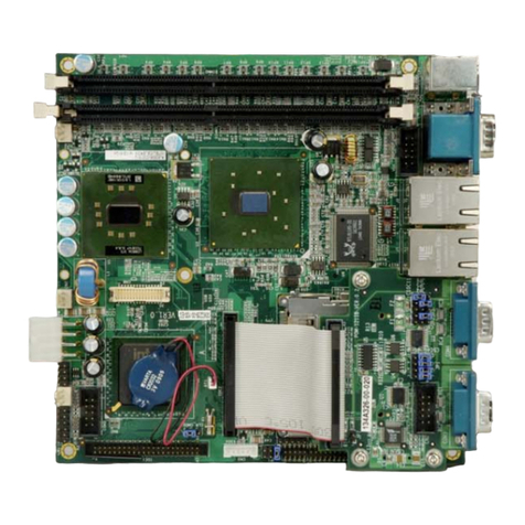
KINO-9455 Mini-ITX CPU Card
Page ix
4.2.3 Backlight Inverter Connector .......................................................................... 44
4.2.4 Battery Connector............................................................................................ 45
4.2.5 Digital Input/Output (DIO) Connector............................................................ 46
4.2.6 Fan Connector (+12V, 3-pin) .......................................................................... 47
4.2.7 Front Panel Connector (14-pin)...................................................................... 48
4.2.8 IDE Connector (40-pin)................................................................................... 49
4.2.9 LVDS LCD Connector ..................................................................................... 51
4.2.10 Mini PCI Slot ................................................................................................. 53
4.2.11 PCI Slot .......................................................................................................... 57
4.2.12 SATA Drive Connectors ................................................................................. 61
4.2.13 Serial Port Connector (COM 2)(RS-232, RS-422 or RS-485)....................... 62
4.2.14 Serial Port Connector (COM 3 and COM4).................................................. 63
4.2.15 SPDIF Connector........................................................................................... 64
4.2.16 USB Connectors (Internal)............................................................................ 65
4.3 EXTERNAL PERIPHERAL INTERFACE CONNECTOR PANEL ......................................... 66
4.3.1 Audio Connector .............................................................................................. 67
4.3.2 Keyboard/Mouse Connector ............................................................................ 67
4.3.3 LAN Connectors............................................................................................... 68
4.3.4 Serial Port Connectors (COM1 )..................................................................... 69
4.3.5 USB Connector ................................................................................................ 70
4.3.6 TV Connector................................................................................................... 71
4.3.7 VGA Connector................................................................................................ 72
5INSTALLATION .................................................................................................... 74
5.1 ANTI-STATIC PRECAUTIONS...................................................................................... 75
5.2 INSTALLATION CONSIDERATIONS ............................................................................. 76
5.2.1 Installation Notices.......................................................................................... 76
5.2.2 Installation Checklist....................................................................................... 77
5.3 CPU, CPU COOLING KITAND DIMM INSTALLATION ............................................. 78
5.3.1 Socket M CPU Installation .............................................................................. 78
5.3.2 Socket M CF-518-RS CPU Cooling Kit Installation ....................................... 81
5.3.3 Cooling Kit CF-479B-RS Installation.............................................................. 83
5.3.4 DIMM Installation........................................................................................... 85
5.4 JUMPER SETTINGS.................................................................................................... 86
5.4.1 Clear CMOS Jumper........................................................................................ 87
