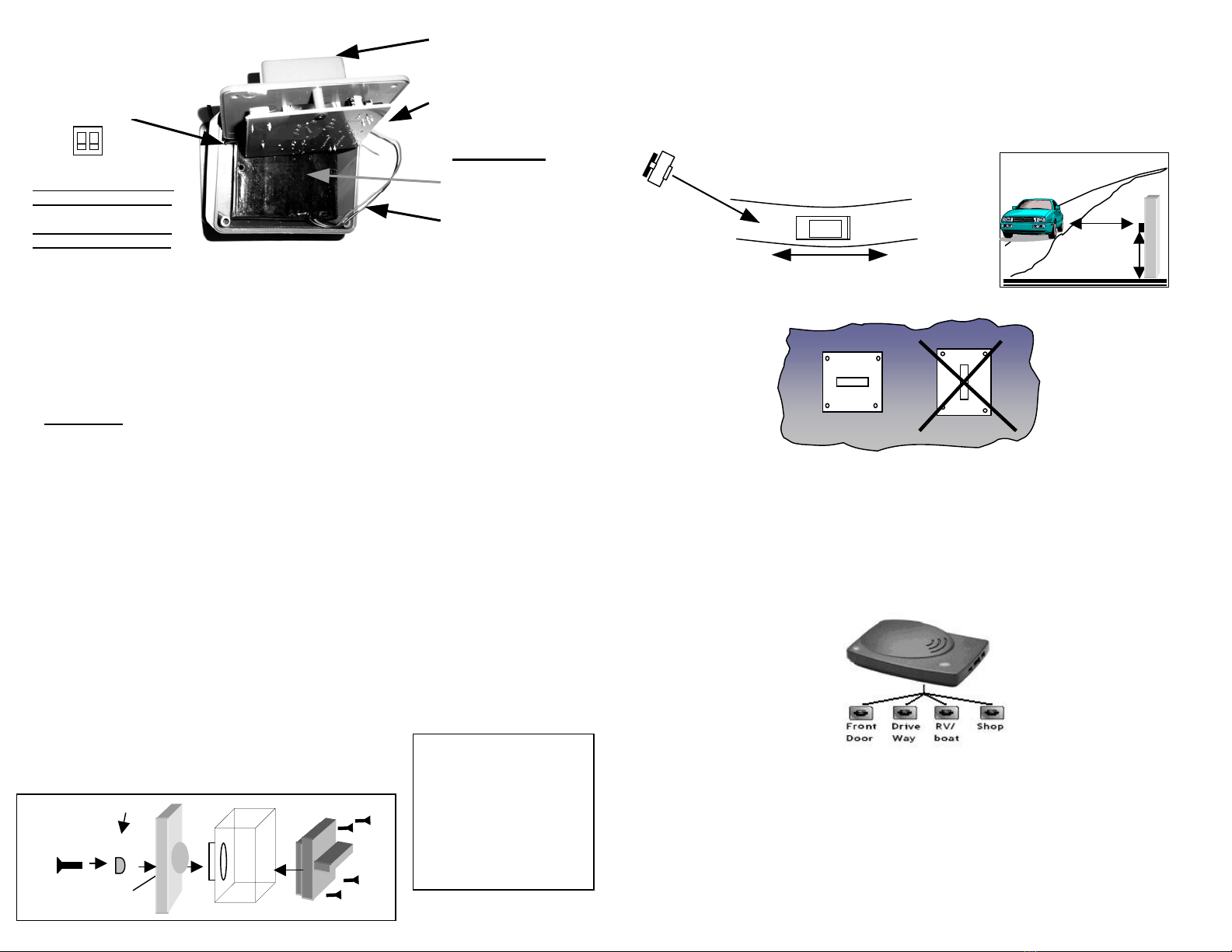
manuals.online logo
Brands
  1. Home
  2. •
  3. Brands
  4. •
  5. IEI Technology
  6. •
  7. Transmitter
  8. •
  9. IEI Technology Reporter PIR-300 User manual

IEI Technology Reporter PIR-300 User manual

Troubleshooting and Frequently Asked Questions
The transmitter lights up with motion, but the receiver does not react
The transmitter must be taught to the base unit, as explained in step 3 in the Set-Up
guide. If the unit was taught, the most common reason for not working is that the base
unit has been turned off, or muted. Press the MUTE button on the top of the base unit. If
it doesn’t start working, press the MUTE button again, to wake the unit up and look at the
two small white switches next to the LEARN button. The #1 white dipswitch, should be
down, towards the circuit board. If it is UP, the unit has been muted.
The transmitter is not getting the expected range
To assure best range; A: Keep both antennas VERTICAL. B: Keeps the PIR Transmitter
antenna away from trees and metal objects (at least 3”). C: Locate the Receiver near a
window with the clearest possible sight of the PIR Transmitter. The less number of
objects between the devices, the longer the range.
I cannot hear the receiver when it signals
The receiver is not made to be overly loud. If you need to have a louder signal, the
receiver has a relay for attaching accessories, such as bells, buzzers, or lights. The relay
is a switch that has no power of it's own, but can handle up-to 120 volts at 10 amps
through it. The relay is essentially an automatic switch and has no power of its own.
The transmitter is picking up people, but not cars
For best results, when detecting cars, adjust the sensor to look at a 45-60 degree angle,
have it about the height of the car’s hot motor, and set it back far enough so the cars
don’t pass within five feet. It can help top have it looking at the back of the car, after
driving past the sensor, to see the car’s hot exhaust.
Sensitivity settings
There are two switches located, next to the test button, on the circuit board inside the
transmitter. The REPORTER is shipped pre-set to its highest level of sensitivity, with
the switches DOWN, towards the circuit board. If you are experiencing false alarms, the
unit may need to be set to be less sensitive.
SW 1: Sensitivity to motion
ON = High OFF = Low
SW 2: Sensing distance from unit
ON = 5-25 Feet OFF = 5- 15 Feet
There is a short beep every ten minutes
The Receiver is indicating that the Battery is LOW. Remove the cover on top of the
Receiver by simply pulling the top and bottom halves apart. Replace the 9V battery with a
fresh alkaline battery or just operate it without a 9V battery.
If you have installation or operation questions, please see above or check out the
expanded FAQ at the manufacturer’s web page at www.internationalelect.com
You can receive free technical assistance on the web at [email protected]
For Warranty email or call 888.679.7994 Tuesday-Friday 8:00-5:00 PST
Warranty: This product is warranted to be free of defects for the period of One Year from the date of
purchase. The warranty covers parts, labor, and return shipping to you, but not all accessories. IEI will
repair or replace any defective product at our discretion. Warranty does not cover misuse or damage other
then due to normal operating conditions. If you need to send the system to IEI for repair, contact IEI for a
Return Authorization number via email: [email protected] Packages without Return Authorization
number will be rejected.
10-28-03
Uses Include…
• Driveways
•
•
•
•
•
•
•
Deck & Patio
Storefronts
Barn or Shop
RVs, while at home
Pools or area security
Home / Office Security
Ignores Animals
Thank you for purchasing
an extra transmitter for
the Reporter Wireless
Alert. This product has
been designed and
manufactured in the USA,
utilizing the highest
quality standards
available. The Reporter
has been designed to
detect and report motion
from people and vehicles,
while allowing animals to
pass through undetected.
Please read the
inst
ructions carefully.
N
ew!
•
Ultra Long Range
•
Crystal Controlled
•
Sun/Rain Shield
Made With Pride In the USA. This product is covered by a
manufacturer’s full One Year Warranty.
Receiver
PIR-300
Transmitter
Face Plate Assembl
y
#1 #2
#1: ON = More Sensitive
PIR sensor
#1: Off = Less Sensitive
#2: ON = 30 Foot Range
#2: Off = 15 Foot Range
1: Assemble the Transmitter Mounting Bracket
Insert the 1” screw (The single larger screws provided in the kit) through the Swivel Bushing
(supplied in the plastic bag), then through the Plate and the Shell. Tighten just enough to
allow the plate to still move, but there should be no “slop” in the movement.
2: Install Batteries in the Transmitter
Place four AA Alkaline batteries in the battery pack (Use only high quality batteries for
longest performance), the LED Light in the PIR window will flash several times to show a
successful systems test. The batteries should last for over Two years with average use.
Important *** Set the battery pack into the transmitter body, so the plastic back is facing
the outwards.
3: Introduce the Transmitter to the Base Unit
Before the Reporter will operate, you have to teach the PIR Transmitter to the Receiver
(Each PIR Transmitter has its own unique ID, so that the Radio Link is Secure). Locate the
Learn button on the back of the Receiver unit. Locate the TEACH button on the PIR unit;
(this is a small round pushbutton, visible from one edge of the PIR transmitter PCB).
A: Press and release the LEARN button on the receiver, the buzzer should sound.
B: Within 5 seconds, press and release the TEST button on the PIR transmitter (If you cannot
locate this button on the PIR Transmitter, simply wave your hand in front of the
detection window instead), the buzzer should sound again. If it does not, repeat steps A
and B. As of this time, the Receiver should respond to motion detected by the sensor.
4: Finish Assembly Of PIR Transmitter
A: As instructed in step 2 above, make sure you have Installed the Battery Pack into the
housing, facing the BATTERIES TO THE BACK OF HOUSING. With the batteries installed, you
should only be able to see the plastic back of the battery pack.
B: Position the Face Plate Assembly so that the Black Antenna Wire is located next to the
Notch Marked “Antenna Here”.
C: Install the 4 screws provided into front holes and tighten.
D: If desired, place the optional sun/rain shield on to the top
of the transmitter by clipping it onto the mounting bracket
joint.
Swivel
Long Screw
Plate
Test button
Sensitivity switches
Mounting the transmitter
Mount the PIR Transmitter onto a solid surface (Should not shake with wind) 3-5 feet above the ground
(depending on the height of the object being detected). For cars, the best mounting position is at about
3’, Looking at the back of the car after passing the sensor, to see the hot exhaust. Swivel the unit so it
gets the best possible view across the path of movement, keeping it as close to horizontal as possible. To
detect small animals, the sensor has to be mounted low enough to see them, usually within a foot of the
ground.
Battery pack
Batteries Face
The Back
Transmitter body
PIR Detector / Transmitter
Face into the road at angle
5-30 feet
3-5 feet
from the ground
Car’s direction of travel
Mount the plate to the back
using the swivel and long
screw provided.
Tighten enough to remove any
slop in the assembly and yet
allow for some movement of
the plate when installed.
After installing the batteries,
insert the battery pack with the
batteries facing the back.
Multiple transmitters or receivers
Each receiver can operate with up to four transmitters, with distinctive
signals for each. Additionally, multiple receivers can work with the same
transmitters to sound the alarm in different places. Just teach each
additional transmitter to the receiver, as with the first one.
YES NO
Mounting Position

Popular Transmitter manuals by other brands

Niko 10-498 manual

Niko

Niko 10-498 manual

Dillinger Labs Dani SKAA Pro owner's manual

Dillinger Labs

Dillinger Labs Dani SKAA Pro owner's manual

Scaime eNod4-B user manual

Scaime

Scaime eNod4-B user manual

Renkforce 34 25 23 operating instructions

Renkforce

Renkforce 34 25 23 operating instructions

Metal Samples MS2700E Operator's manual

Metal Samples

Metal Samples MS2700E Operator's manual

Mueller Systems Mueller Cellular Node installation manual

Mueller Systems

Mueller Systems Mueller Cellular Node installation manual

NIVELCO NIVOTRACK M-300 series Installation and programming manual

NIVELCO

NIVELCO NIVOTRACK M-300 series Installation and programming manual

LINK-MI LM-DT200 user manual

LINK-MI

LINK-MI LM-DT200 user manual

BWI Eagle AIR-EAGLE XLT Product information bulletin

BWI Eagle

BWI Eagle AIR-EAGLE XLT Product information bulletin

Crestron DM-TX-4K-202-C manual

Crestron

Crestron DM-TX-4K-202-C manual

Sartorius GWT MP 25 operating instructions

Sartorius

Sartorius GWT MP 25 operating instructions

Paso SDM200 Instructions for use

Paso

Paso SDM200 Instructions for use

Lake Shore 234 user manual

Lake Shore

Lake Shore 234 user manual

SkyLink G6T2 manual

SkyLink

SkyLink G6T2 manual

Listen lt-800 user manual

Listen

Listen lt-800 user manual

MTT MS3702 user manual

MTT

MTT MS3702 user manual

Nautel FM10 Technical instructions

Nautel

Nautel FM10 Technical instructions

Ramsey Electronics QRP40 instruction manual

Ramsey Electronics

Ramsey Electronics QRP40 instruction manual

manuals.online logo
manuals.online logoBrands
  • About & Mission
  • Contact us
  • Privacy Policy
  • Terms and Conditions

Copyright 2025 Manuals.Online. All Rights Reserved.