IEMAI HIGH-TEMPERATURE Series User manual

Print More Materials, All For Application
HIGH-TEMPERATURE SERIES
3D PRINTER
MAGIC-HT-MAX
Operating Instructions
www.iemai3d.com
* Please read this manual carefully before starting to operate.
This device is a Class A product. Use in a general indoor environment
may cause radio interference and therefore requires the user to take
appropriate protective measures.


Print More Materials, All For Application
- 3 -
Content
1. Overview.........................................................................................................................................................................................- 4 -
1.1 Printer Overview............................................................................................................................................................... - 4 -
1.2 Precautions.........................................................................................................................................................................- 5 -
1.3 Safety....................................................................................................................................................................................- 6 -
2. Detailed Parameter.....................................................................................................................................................................- 7 -
2.1 Specification.......................................................................................................................................................................- 7 -
2.2 Device Layout.................................................................................................................................................................... - 9 -
2.3 Interactive Interface.......................................................................................................................................................- 13 -
2.3.1 System Interface.................................................................................................................................................- 14 -
2.3.2 Tool Interface......................................................................................................................................................- 15 -
2.3.3 Print Interface..................................................................................................................................................... - 16 -
3. Device Usage..............................................................................................................................................................................- 17 -
3.1 Unpacking........................................................................................................................................................................ - 17 -
3.2 Check Equipment Motion........................................................................................................................................... - 18 -
4. Print Operation.......................................................................................................................................................................... - 19 -
4.1 Install Print Platform And Leveling...........................................................................................................................- 19 -
4.1.1 Use Auto Leveling To Print.............................................................................................................................- 20 -
4.1.2 Use Mechanical and electronic limit to Print............................................................................................- 23 -
4.2 Load/Unload Filament..................................................................................................................................................- 24 -
4.3 Start Printing....................................................................................................................................................................- 26 -
4.4 Disassembly Model....................................................................................................................................................... - 27 -
4.5 PEEK Material Printing Precautions..........................................................................................................................- 27 -
4.6 PC-Based WIFI LAN control....................................................................................................................................... - 28 -
5. Function Introduction.............................................................................................................................................................. - 29 -
5.1 Power Failure Recovery................................................................................................................................................- 29 -
5.2 Filament Absent Warning............................................................................................................................................- 29 -
5.3 Chamber Temperature Setting..................................................................................................................................- 30 -
5.4 Moisture Proof Cabinet Setting.................................................................................................................................- 31 -
6. Maintenance and Care............................................................................................................................................................- 32 -
6.1 Maintenance of Linear Guide and Ball Screw.......................................................................................................- 32 -
6.2 Dust Removal from Electrical Box Fans.................................................................................................................. - 33 -
6.3 Nozzle Maintenance..................................................................................................................................................... - 34 -
6.4 Height Adjustment for Dual Nozzle........................................................................................................................ - 35 -
6.5 Dual Nozzle Spacing Adjustment Method............................................................................................................- 36 -
6.6 Print Head Disassembly............................................................................................................................................... - 37 -
7. Common Problems and Their Solutions........................................................................................................................... - 38 -
7.1 Movement........................................................................................................................................................................- 38 -
7.2 Temperature....................................................................................................................................................................- 38 -
7.3 Print.................................................................................................................................................................................... - 39 -
7.4 Clean Up Carbon Blockage.........................................................................................................................................- 40 -
Appendix A:..................................................................................................................................................................................- 41 -
Appendix B:..................................................................................................................................................................................- 42 -
Print More Materials, All For Application
- 4 -
1. Overview
1.1 Printer Overview
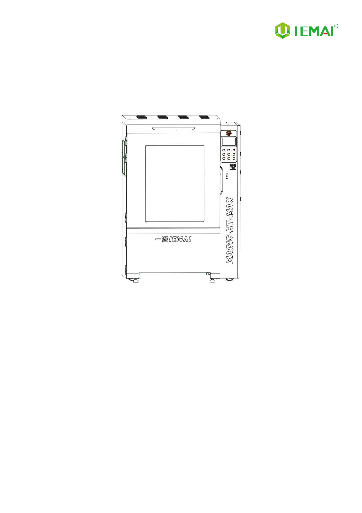
IEMAI high-performance material 3D printer, the Magic-HT-MAX, is a 3D printing equipment
based on the principle of fused filament fabrication (FFF) technology. It has a printing temperature of
up to 500℃, a hot bed temperature of 200℃, and a chamber temperature of 150℃, which supports
most polymer 3D printing materials in the market, including PEEK, PEKK, PPSU, PEI 1010/9085 and
other high performance materials, nylon, PC, ABS, PETG, ASA, TPU, PLA and other general engineering
materials, and composite reinforcement materials of the above materials (carbon fiber, glass fiber,
flame retardant, anti-static, etc.).
The MAGIC-HT-MAX comes with individual lifting dual print head that supports the printing of
support materials, including water-soluble PVA, limonene soluble HIPS, easy remove support
materials and high temperature resistant support materials. We use a modular design, for example,
the print head and the platform can be quickly disassembled, thus creating conditions for easy
maintenance.

Print More Materials, All For Application
- 5 -
1.2 Precautions
First of all, thank you for choosing IEMAI 3D Printer!
This device is a Professional equipment, please read this manual carefully before starting to use,
this manual contains important information about the installation, operation, maintenance, and
common problems of the 3D printer, the company is not responsible for all losses caused by violation
of the cautions and operating procedures given in this manual。
Consumables: Please use the filament provided by our company or the third-party filament of
official authorized brand or choose the high-quality filament provided by other regular filament
manufacturers, and users should be responsible for the loss caused by using low-quality filament.
Please keep the consumables sealed and moisture-proof if not in use for a long time; please bake and
dry them in advance before using them again.
Software: Please use a 64-bit system with Windows 7 or above to run the software, more than
4G of RAM and more than 1G of GPU, please use a computer with a higher configuration if possible.
Installation Site Requirements: Installation Site≥2010*2300*2700mm (L*W*H)。
Installation Power Requirements:200~250 V, 50~60 Hz, 6500w,Electric cable 6 m2or more.
Operating Environment: 15-30°C, 10-85% Relative Humidity, non-condensation
Storage Environment: 25-55°C, 10-85% Relative Humidity, non-condensation

Print More Materials, All For Application
- 6 -
1.3 Safety
The device has a specialized motion structure, control system and electrical control parts, users
need to pay careful attention to the safety label when using it to prevent burns, pinching, electric
shock or other safety problems.
The maximum temperature of the print head of this equipment can reach 500 °
C, its heating is strictly prohibited to touch
The maximum temperature of the printing platform of this equipment can reach
200°C, its heating is strictly prohibited to touch
The maximum temperature of the chamber of this equipment can reach 150°C,
and it is strictly forbidden to touch it when it is heated.
Ensure that the power supply grounding terminal is well grounded to prevent the
printer from not working properly or posing a risk of electric shock
Do not disassemble the case without permission, be careful of electric shock
When the printer is working, it is forbidden to move in the printing area to
prevent collision, belt turning in, etc.

Print More Materials, All For Application
- 7 -
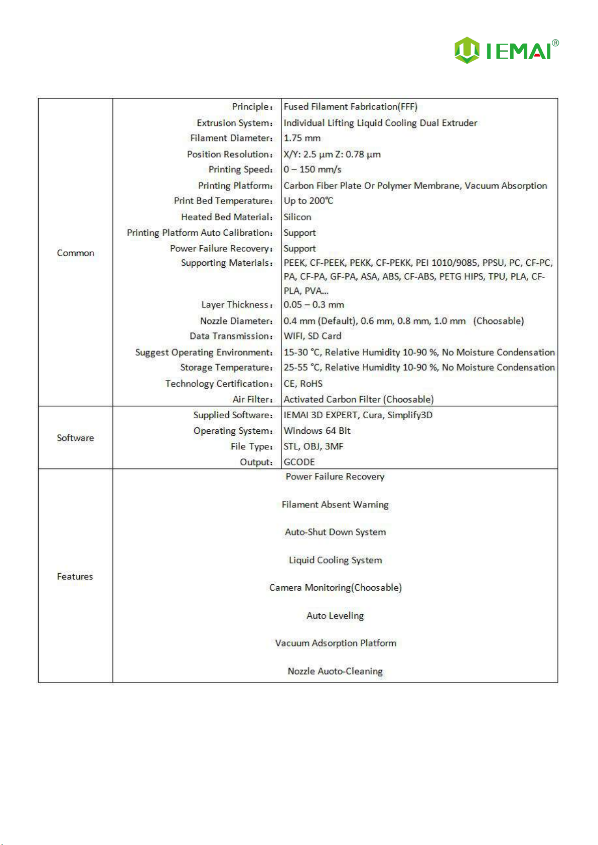
2. Detailed Parameter
2.1 Specification
Print More Materials, All For Application
- 8 -
Print More Materials, All For Application
- 9 -
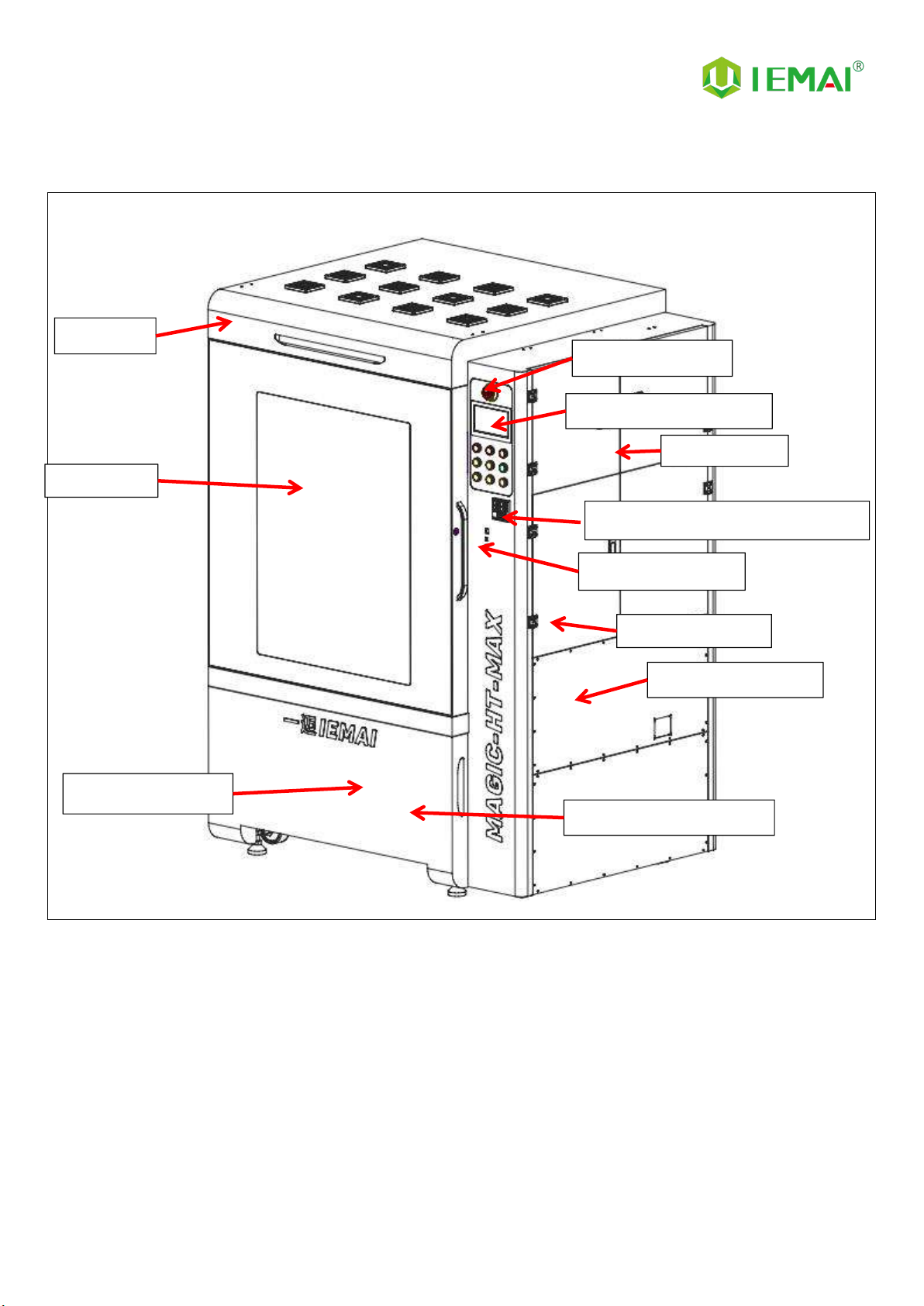
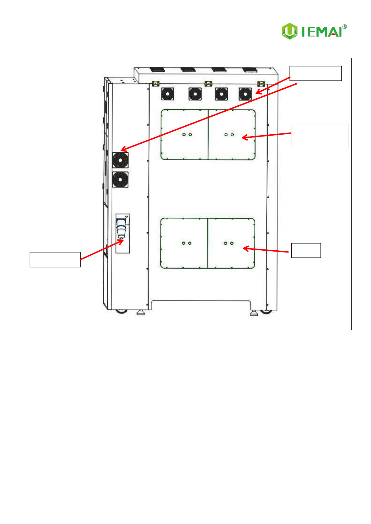
2.2 Device Layout
Filament Box
Emergency Stop
7-Inch Touch Screen
Chamber Temperature Controller
Main Electric Box
Date Transfer Area
Vacuum Pump Box
Moisture-Proof Storage
Material Box Door
Front Door
Top Cover

Print More Materials, All For Application
- 10 -
Internal Chamber
Print More Materials, All For Application
- 11 -
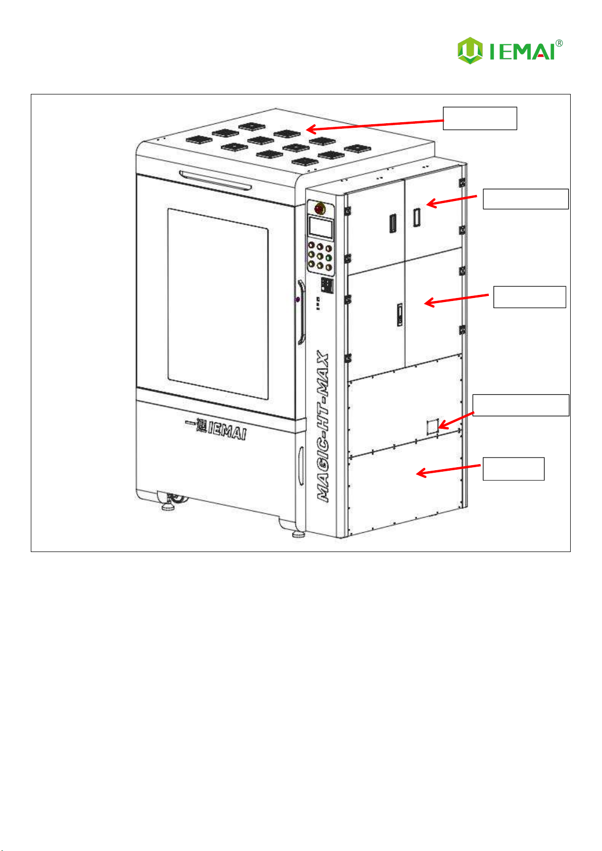
Filament Box
Electric Box
Pressure Gauge
Air Pump
Cooling Fan
Print More Materials, All For Application
- 12 -
Cooling Fan
Built-In Light
Built-In Camera
Motor
Power Outlet

Print More Materials, All For Application
- 13 -
2.3 Interactive Interface
The interactive interface of the device adopts a 7-inch Chinese-English color touch
screen (resistive). Please read the following interface instructions carefully before first
use.
Logic diagram of interactive interface
Print More Materials, All For Application
- 14 -
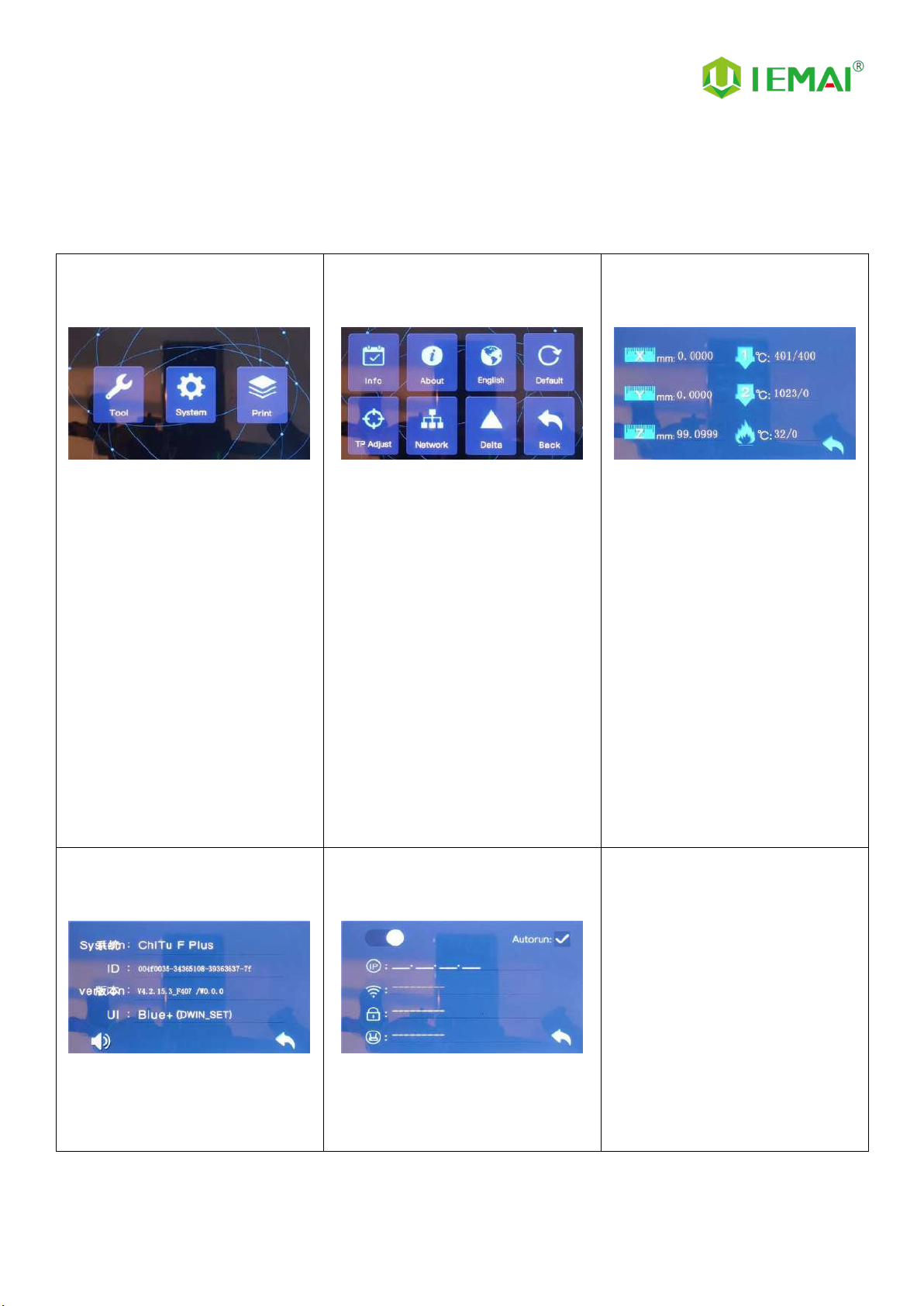
2.3.1 System Interface
Figure 1: Main interface
Click "System" to go to Figure 2
Figure 2: System interface
1. Click "Info" to go to Figure 3
2. Click "About" to go to Figure
4
3. Click "English" to switch to other
Language
4. Click "Default" to restore the
original factory settings
5. Tap TPAAdjustment to correct
the touch offset
6. Click "WIFI" to go to Figure 5
Figure 3: Info interface
1. This interface allows you to
view the current coordinates of
the XYZ axis
2. The current temperature of the
left nozzle, and right nozzle,
and hot bed
Figure 4: About interface
This interface allows you to view the
name, ID, system version, UI
version, and Power On/Off sounds
Figure 5: WiFi Setup Interface
This interface allows you to view
information about Wi-Fi

Print More Materials, All For Application
- 15 -
2.3.2 Tool Interface
Figure 1: Main interface
Click "Tool" to go to Figure 2
Figure 2: Tool Interface
1. Click "Manual" to go to Figure 3
2. Click "Preheat" to go to Figure 4
3. Click "Filament” to go to Figure 5
4. Click "Level" to perform
automatic leveling
5. Click "Fan" to go to Figure 6
6. Click "Stop" to stop all execution
commands
7. Click "More" to view the
after-sales contact information
Figure 3:Manual
Here can do the following
1. Select the moving unit of
0.1-10mm
2. Controls the XYZ axis for unit
movement
3. Click “ ” to go back to the
original point"
4. Select E1 or E2 for unit
extrusion
Figure 4: Pre-Heat interface
1. This interface allows you to
set the preheat temperature
of the hot bed, left nozzle
and Right nozzle
Figure 5: Filament interface
1. Loading material “ ”
2. Unload material “ ”
3. E1- Left Nozzle,E2-Right Nozzle
4. “ ”Stop Loading Command
Figure 6: Fan Interface
1. This interface allows you to set
the nozzle cooling fan E1,
nozzle cooling fan E2 and the
fan rate of the motherboard
fan

Print More Materials, All For Application
- 16 -
2.3.3 Print Interface
Figure 1: Main Interface
Click "Print" to go to Figure 2
Figure 2: File Interface
Check Specify G-code file to print or
delete the file
Figure 3: Print Interface
1. This interface is the main
interface in print You can view
thumbnails
2. Hot bed, Nozzle Temperature
and chamber temperature
3. Elapsed time, Time remaining、
Current speed
4. File name, Print Progress Bar
5. You can control pause (resume)
and stop printing
6. Press " " to Figure 4
Figure 4:Print Setting Interface
1. This interface can be adjusted
during the printing process
2. Print Speed Ratio, Temperature
of Hot Bed, Nozzle
3. Fan Rate of E1/E2 and Chamber
4. Extrusion flow
5. Setting power off after printing
Print More Materials, All For Application
- 17 -
3. Device Usage
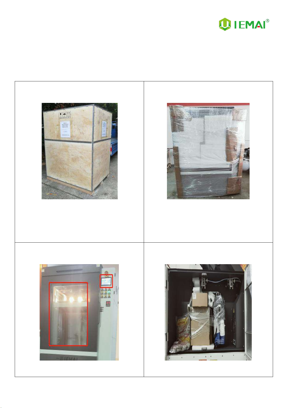
3.1 Unpacking
Step 1
1. Check if the packaging is complete
2. If there is a damage, please feedback by taking
photos in time
3. If serious damage, please refuse to receive
Step 2
1. The equipment is tightly packed and protected
2. Please be patient in removing the package
3. If you need to use tools, such as knives, scissors
4. Please be cautioned to avoid scratching the device
Step 3
Check whether the door glass and control panel are in
good condition
Step 4
Note: The starter kit and material pack are placed in
the material box on the right

Print More Materials, All For Application
- 18 -
3.2 Check Equipment Motion
Step 1
Use 6mm² cable to connect
AC220V single-phase power socket
Step 2
Plug in the power connector at the
rear of the machine to the main
power supply
Step 3
It is shown in Figure 3
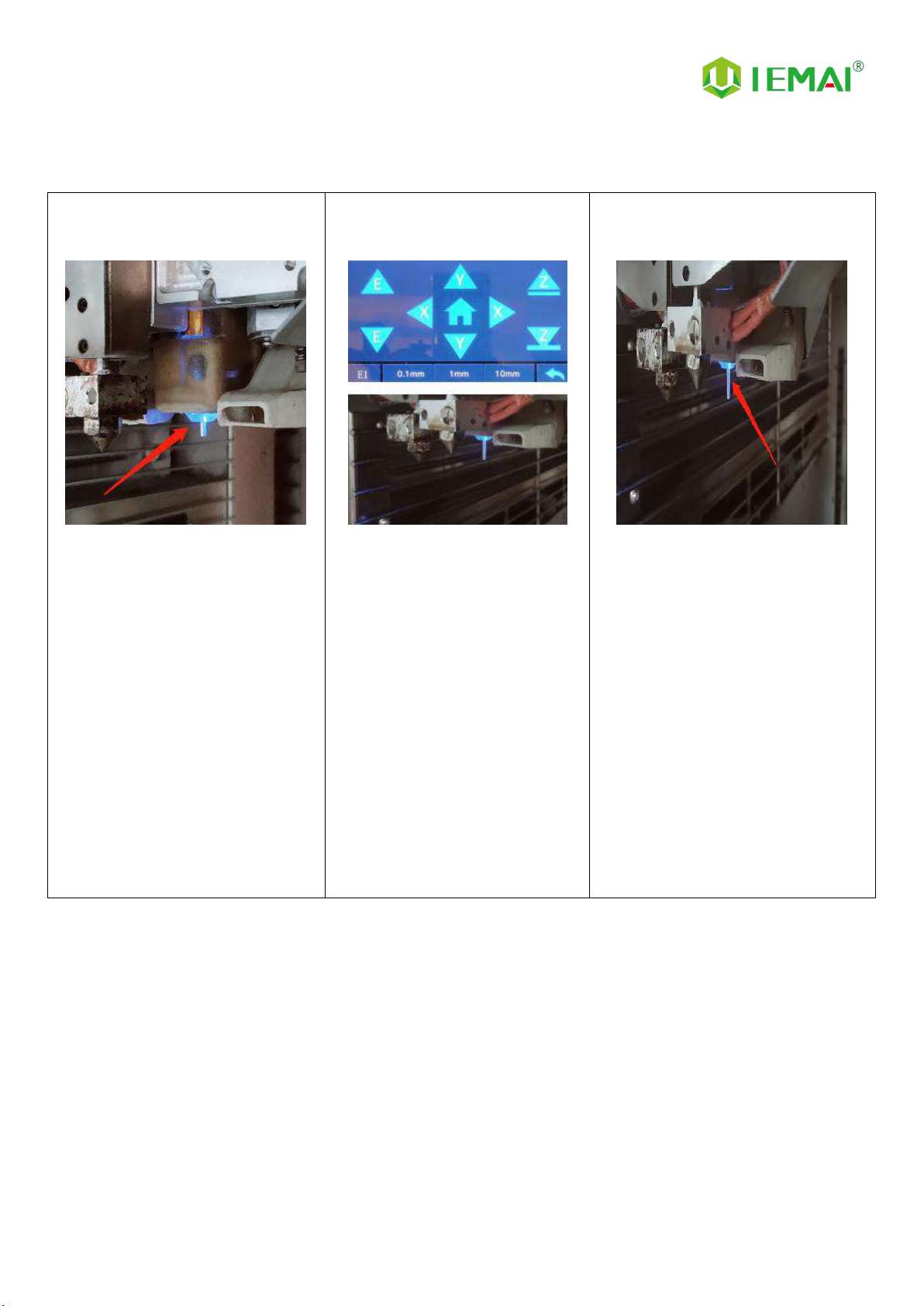
Step 4
1. The XYZ axis movement is
controlled manually by touch
screen
2. Observe whether the figure
moves normally
Step 5
1. Control E1 and E2 extrusion
through the touch screen
2. Check whether the gears of the
left and right sprinklers rotate
clockwise
Step 6
1. Preheat through touch screen
2. It can set the temperature of hot
bed, left nozzle and right nozzle
3. The temperature on the right
represents the set temperature,
and the temperature on the left
represents the actual temperature
4. Recommended hot bed
temperature for first preheating:
50 ° C ±2 ° C
5. Left and right nozzle
temperature: 210℃±2℃
Please be careful with high
temperature and operate with
caution

Print More Materials, All For Application
- 19 -
4. Print Operation
4.1 Install Print Platform And Leveling
Step 1
Install sealing strips
Step 2
Install carbon fiber plate
Step 3
Turn on the vacuum suction switch
Print More Materials, All For Application
- 20 -
4.1.1 Use Auto Leveling To Print
Step 1
When starting the machine,
observe whether the automatic
leveling self-test passes. If it does
not pass, it must not be reset to
zero, otherwise there is a risk that
the platform will hit the nozzle,
resulting in machine failure.
(During the self-test, the self-test
will be performed twice. If there is
no action, manually pull out the
probe and start the self-test again)
Step 2
After passing the self-test, click
return to zero
Step 3
The X-axis (transverse) Y-axis
(vertical) is zeroed in turn, , and
finally the Z-axis is raised and
zeroed
This manual suits for next models
1
Table of contents
Other IEMAI 3D Printer manuals


Popular 3D Printer manuals by other brands


Ortur
Ortur Laser Master 2 PRO S2 user manual

3DMakerWorld
3DMakerWorld Artifex 2 user manual

Geeetech
Geeetech Delta Rostock mini G2 pro Building Instruction

3DUniverse
3DUniverse FlashForge Creator X manual

Prusa Research
Prusa Research Original Prusa SL1 manual

Flashforge
Flashforge Creator 3 Pro user guide


