IEMAI Large Scale User manual
Print More Materials, All For Application
Large Scale 3D Printer
YM-NT-750
Operating Instructions
www.iemai3d.com
* Please read this manual carefully before starting to operate.
This device is a Class A product. Use in a general indoor environment may
cause radio interference and therefore requires the user to take appropriate
protective measures.

Print More Materials, All For Application
The contents of this operating instructions may be updated periodically. Scan the QR
code or visit the link below to get the latest version.
www.iemai3d.com/index.php/download/

Print More Materials, All For Application
Content
1.Overview..................................................................................................................................................................... 1
1.1 Machine Overview.............................................................................................................................................1
1.2 Precautions........................................................................................................................................................ 2
1.3 Safety.................................................................................................................................................................. 3
2. Detailed Parameter...................................................................................................................................................... 4
2.1. Specification......................................................................................................................................................4
2.2 Device Layout.................................................................................................................................................... 6
2.3 Interactive Interface...........................................................................................................................................9
3.Device Usage............................................................................................................................................................... 14
3.1 Unboxing for The First Time...........................................................................................................................14
3.2 Power Installation............................................................................................................................................ 16
3.3 Hardware Checking.........................................................................................................................................17
4. Print Operation...........................................................................................................................................................19
4.1 Installation of The Printing Platform and Auto-Calibration........................................................................ 19
4.3 Start Printing.................................................................................................................................................... 24
4.4 Model Removal............................................................................................................................................... 25
4.5 PC-based WIFI LAN Control.......................................................................................................................... 26
5. Function Introduction................................................................................................................................................ 27
5.1 Power Failure Recovery...................................................................................................................................27
5.2 Filament Absent Warning............................................................................................................................... 27
6. Maintenance and Care.............................................................................................................................................. 28
6.1 Maintenance of Linear Guide and Ball Screw............................................................................................... 28
6.2 Dust Removal from Fans.................................................................................................................................29
6.3 Nozzle Maintenance....................................................................................................................................... 30
6.4 Dual Print Head Nozzle Spacing Adjustment Method................................................................................ 32
6.5 Print Head Disassembly and Maintenance................................................................................................... 33
7. Common Problems and Their Solutions..................................................................................................................39
7.1 Movement........................................................................................................................................................39
7.2 Temperature.................................................................................................................................................... 40
7.3 Print.................................................................................................................................................................. 40
8. Appendix A................................................................................................................................................................. 43
Print More Materials, All For Application
— 1 —
1.Overview
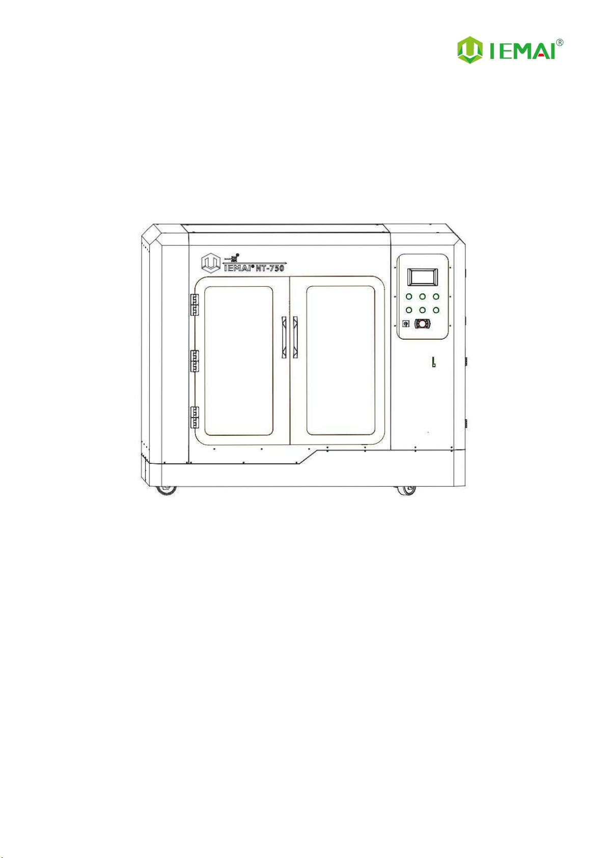
1.1 Machine Overview
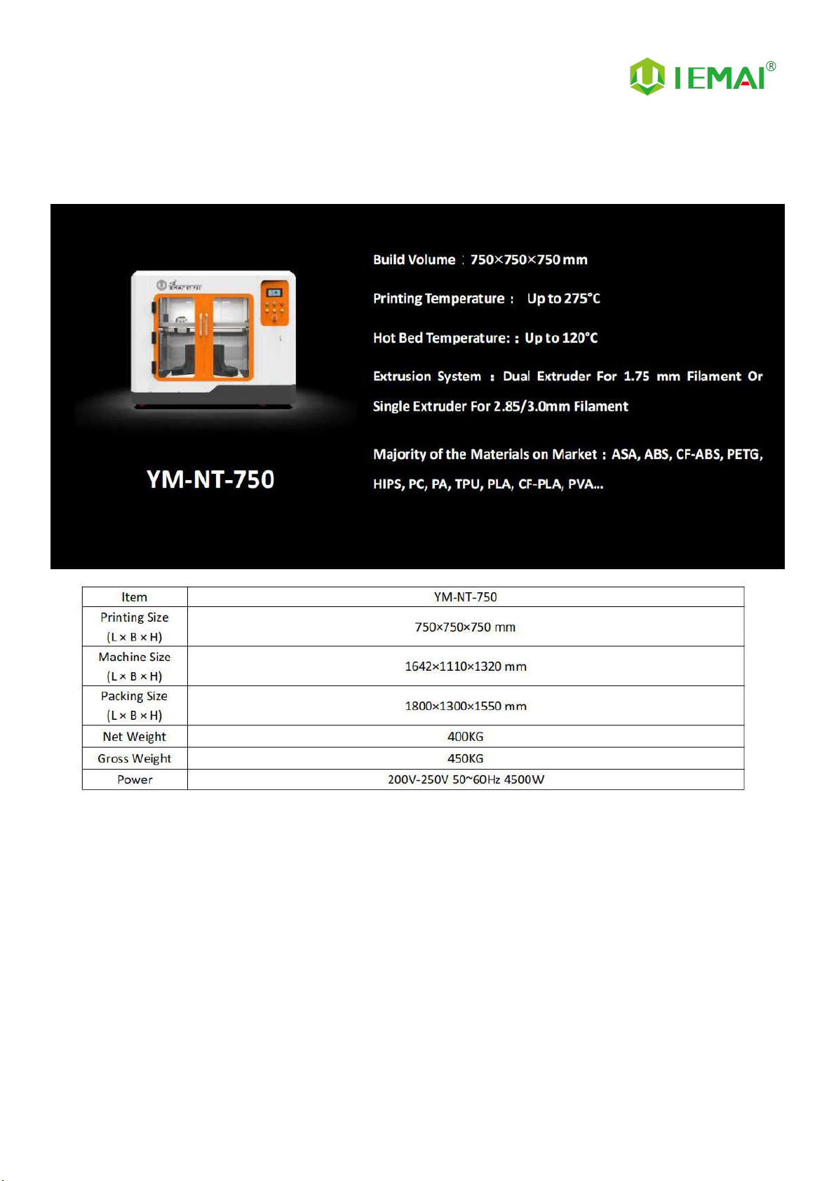
IEMAI’s Large Scale 3D printer YM-NT-750 based on the principle of fused filament deposition
(FFF) technology, with a printing temperature of up to 275 ℃ printing temperature , a hot bed
temperature of 120℃,It supports most polymer 3D printing materials on the market, including ASA,
ABS, PC, PA, CF-ABS, PETG, HIPS, TPU, PLA, CF-PLA, PVA.
YM-NT-750 Print Head can adopt Dual Print Heads(1.75mm Filament)or Single Print Head
(2.85/3.0mm filament),these print heads are modular and can be quickly replaced by the user.
When you use dual print heads, it can support using support materials, including water-soluble
material PVA, limonene soluble material HIPS, and when you use separate high flow print heads, you
can use large layer thickness fast printing mode.

Print More Materials, All For Application
— 2 —
1.2 Precautions
First of all, thank you for choosing IEMAI 3D Printer!
This Printer is a Professional equipment, please read this manual carefully before starting to use,
this manual contains important information about the installation, operation, maintenance, and
common problems of the 3D printer, the company is not responsible for all losses caused by violation
of the cautions and operating procedures given in this manual。
Materials: Please use the filament provided by our company or the third-party filament of official
authorized brand or choose the high-quality filament provided by other regular filament
manufacturers, and users should be responsible for the loss caused by using low-quality filament.
Please keep the consumables sealed and moisture-proof if not in use for a long time; please bake and
dry them in advance before using them again.
Software: Please use a 64-bit system with Windows 7 or above to run the software, more than
4G of RAM and more than 1G of GPU, please use a computer with a higher configuration if possible.
Installation Site Requirements: Installation Site≥2300*1900*1400mm (L*W*H).
Installation Power Requirements:200~250 V, 50~60 Hz,4500w,Electric cable 4 m2or more.
Operating Environment: 15-30°C, 10-90% Relative Humidity, non-condensation.
Storage Environment: 25-55°C, 10-90% Relative Humidity, non-condensation.

Print More Materials, All For Application
— 3 —
1.3 Safety
The printer has a specialized motion structure, control system and electrical control parts, users
need to pay careful attention to the safety label when using it to prevent burns, pinching, electric
shock, or other safety problems.
The maximum temperature of the print head of this equipment can reach 275°
C, its heating is strictly prohibited to touch.
The maximum temperature of the printing platform of this equipment can
reach 120 °C, its heating is strictly prohibited to touch.
Ensure that the power supply grounding terminal is well grounded to prevent
the printer from not working properly or posing a risk of electric shock.
Do not disassemble the case without permission, be careful of electric shock.
When the printer is working, it is forbidden to move in the printing area to
prevent collision, belt turning in, etc.
Print More Materials, All For Application
— 4 —
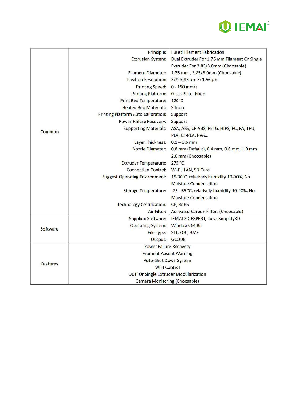
2. Detailed Parameter
2.1. Specification
Print More Materials, All For Application
— 5 —
Print More Materials, All For Application
— 6 —
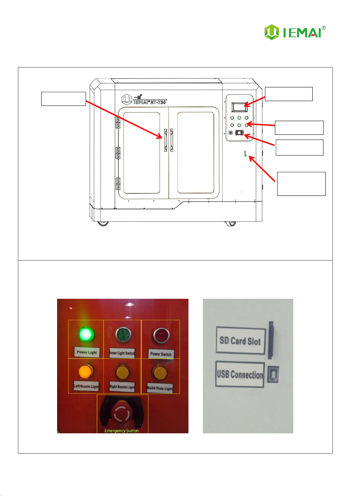
2.2 Device Layout
Front
Control Panel SD Card Slot and USB Connection
Single Door
Touch screen
Control Panel
Main Switch
SD Card Slot
USB Port
Print More Materials, All For Application
— 7 —
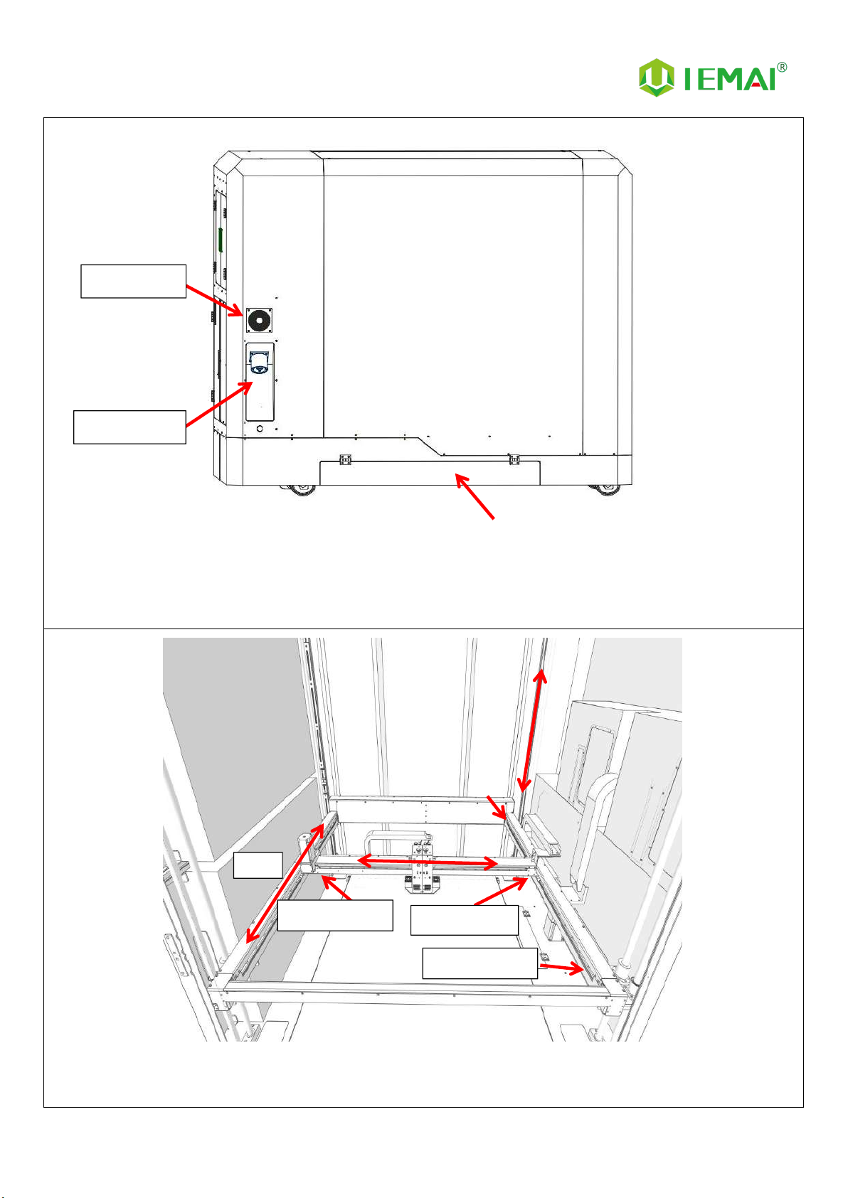
Back
Printer (Internal)
Cooling Fan
Power Port
Y-Axis
Positive X-Axis Limit
Negative X-Axis Limit
Negative Y-Axis Limit
Other manuals for Large Scale
1
This manual suits for next models
1
Table of contents
Other IEMAI 3D Printer manuals


