IEMAI MAGIC-HT-PRO User manual

Print More Materials, All For Application
HIGH-TEMPERATURE SERIES
3D PRINTER
MAGIC-HT-PRO
Operating Instructions
www.iemai3d.com
* Please read this manual carefully before starting to operate.
This device is a Class A product. Use in a general indoor environment
may cause radio interference and therefore requires the user to take
appropriate protective measures.

Print More Materials, All For Application
The contents of this operating instructions may be updated periodically. Scan the QR code or visit the
link below to get the latest version.
www.iemai3d.com/index.php/download/

Print More Materials, All For Application
1
Content
1. Overview................................................................................................................................................................................................2
1.1 Printer Overview...................................................................................................................................................................... 2
1.2 Precautions................................................................................................................................................................................3
1.3 Safety...........................................................................................................................................................................................4
2. Detailed Parameter............................................................................................................................................................................5
2.1. Specification.............................................................................................................................................................................5
2.2 Device Layout...........................................................................................................................................................................6
2.3 Interactive interface................................................................................................................................................................8
2.3.1 System Interface..........................................................................................................................................................9
2.3.2 Tool interface.............................................................................................................................................................10
2.3.3 Print interface............................................................................................................................................................ 11
3.Device Usage......................................................................................................................................................................................12
3.1 Unboxing for The First Time..............................................................................................................................................12
3.2 Check the Refrigerant..........................................................................................................................................................13
3.3 Hardware Check....................................................................................................................................................................14
4. Print Operation.................................................................................................................................................................................15
4.1 Use of The Printing Platform.............................................................................................................................................15
4.2 How to Calibrate................................................................................................................................................................... 16
4.3 Unload Filament....................................................................................................................................................................18
4.4 Start printing.......................................................................................................................................................................... 20
5. Function Introduction.....................................................................................................................................................................21
5.1 Power Failure Recovery.......................................................................................................................................................21
5.2 Filament Absent Warning.................................................................................................................................................. 21
5.3 Temperature Setting of The Constant Temperature Chamber............................................................................. 22
5.4 Moisture Proof Cabinet Setting ....................................................................................................................................... 23
5.5 PC-based WIFI LAN control..............................................................................................................................................24
6. Maintenance and Care...............................................................................................................................................................25
6.1 Maintenance of Linear Guide And Ball Screw............................................................................................................. 25
6.2 Adjustment of Belt Looseness.......................................................................................................................................... 26
6.3 Dust Removal from Electrical Box Fans......................................................................................................................... 27
6.4 Nozzle Maintenance............................................................................................................................................................28
6.5 Equal Height Adjustment for Dual Print Heads..........................................................................................................29
6.6 Dual Print Head Auto-Switching Setting Method..................................................................................................... 30
6.7 Dual Print Head Nozzle Spacing Adjustment Method.............................................................................................31
6.8 Print Head Disassembly and Maintenance...................................................................................................................32
6.9 Coolant Addition...................................................................................................................................................................33
6.10 Use And Maintenance Of Desiccant............................................................................................................................ 34
7. Common Problems and Their Solutions.............................................................................................................................. 35
7.1 Movement...............................................................................................................................................................................35
7.2 Temperature...........................................................................................................................................................................35
7.3 Print........................................................................................................................................................................................... 36
7.4 Clean Up Carbon Blockage............................................................................................................................................... 37
8. Appendix:....................................................................................................................................................................................38
Appendix A.................................................................................................................................................................................... 38
Appendix B.....................................................................................................................................................................................39
Print More Materials, All For Application
2
1. Overview
1.1 Printer Overview
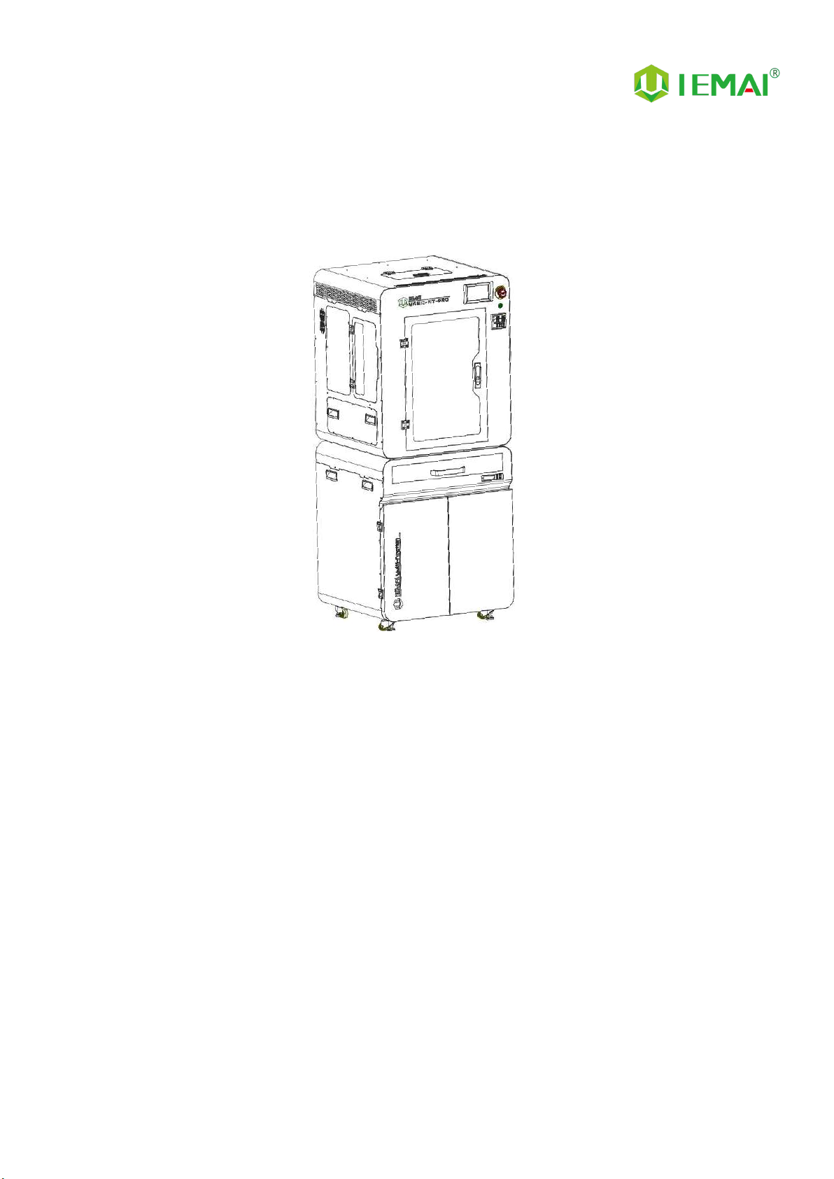
IEMAI High-Performance 3D printer MAGIC-HT-PRO is a 3D Printer based on the principle of
Fused Filament Fabrication (FFF) technology , has a print temperature up to 500 ° C , Hot bed
temperature of 200 °C,and a chamber temperature of 120 °C,Supports most of the polymer 3D
printing materials on the market , include PEEK 、 PEKK 、 PPSU 、 PEI 1010/9085 and other
high-performance materials nylon、PC、ABS、PETG、ASA、TPU and other engineering materials,
common material of the PLA class,And composite reinforcement materials of the above materials
(carbon fiber, glass fiber, flame retardant, ESD, etc.).
MAGIC-HT-PRO is equipped with a dual print head that lifts independently and support the
printing of support materials, including water-soluble material PVA, limonene-soluble material HIPS,
easy-peel support material and high-temperature resistant support material. Our modular design,
such as the printhead and the platform, can be disassembled easily, creating conditions for easy
maintenance.

Print More Materials, All For Application
3
1.2 Precautions
First of all, thank you for choosing IEMAI 3D Printer!
This device is a Professional equipment, please read this manual carefully before starting to use,
this manual contains important information about the installation, operation, maintenance, and
common problems of the 3D printer, the company is not responsible for all losses caused by violation
of the cautions and operating procedures given in this manual。
Consumables: Please use the filament provided by our company or the third-party filament of
official authorized brand or choose the high-quality filament provided by other regular filament
manufacturers, and users should be responsible for the loss caused by using low-quality filament.
Please keep the consumables sealed and moisture-proof if not in use for a long time; please bake and
dry them in advance before using them again.
Software: Please use a 64-bit system with Windows 7 or above to run the software, more than
4G of RAM and more than 1G of GPU, please use a computer with a higher configuration if possible.
Installation Site Requirements: Installation Site≥1200*1400*2000mm (L*W*H)。
Installation Power Requirements:200~250 V, 50~60 Hz, 3050w,Electric cable 2.5 m2or more.
Operating Environment: 15-30°C, 10-85% Relative Humidity, non-condensation
Storage Environment: 25-55°C, 10-85% Relative Humidity, non-condensation

Print More Materials, All For Application
4
1.3 Safety
The device has a specialized motion structure, control system and electrical control parts, users
need to pay careful attention to the safety label when using it to prevent burns, pinching, electric
shock or other safety problems.
The maximum temperature of the print head of this equipment can reach 500 °
C, its heating is strictly prohibited to touch
The maximum temperature of the printing platform of this equipment can reach
200°C, its heating is strictly prohibited to touch
The maximum temperature of the chamber of this equipment can reach 120°C,
and it is strictly forbidden to touch it when it is heated.
Ensure that the power supply grounding terminal is well grounded to prevent the
printer from not working properly or posing a risk of electric shock
Do not disassemble the case without permission, be careful of electric shock
When the printer is working, it is forbidden to move in the printing area to
prevent collision, belt turning in, etc.

Print More Materials, All For Application
5
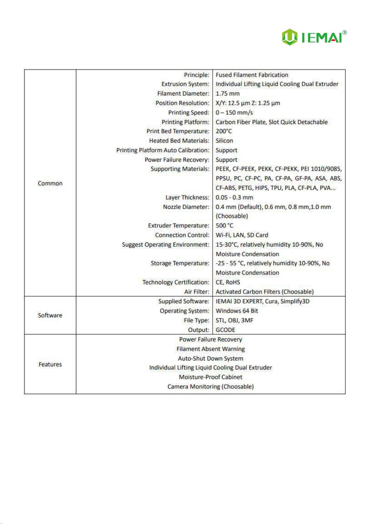
2. Detailed Parameter
2.1. Specification
Print More Materials, All For Application
6

Print More Materials, All For Application
7
2.2 Device Layout

Print More Materials, All For Application
8
2.3 Interactive Interface
The interactive Interface of this device adopts a 5-inch Color Touch Screen (Resistive), please
read the following instructions carefully before first use
Logic diagram of interactive interface
Print More Materials, All For Application
9
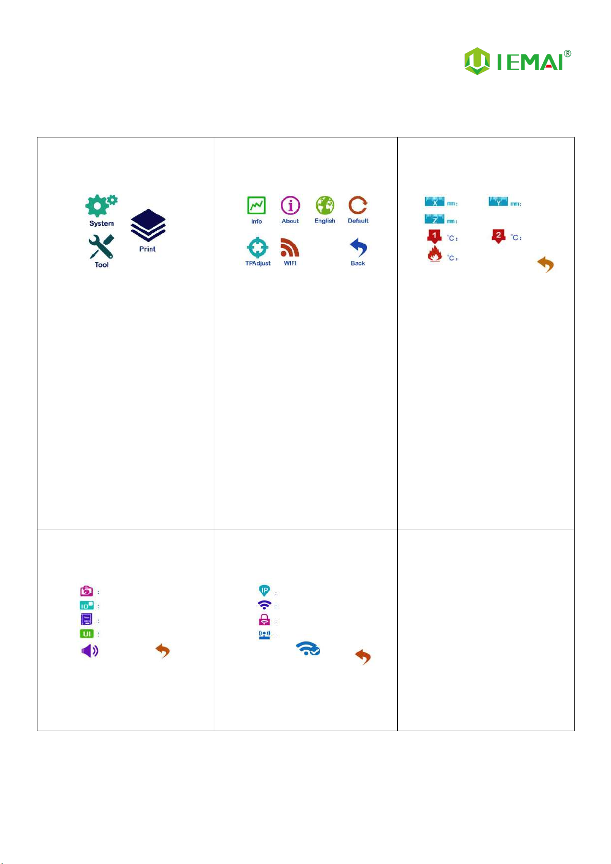
2.3.1 System Interface
Figure 1: Main interface
Click "System" to go to Figure 2
Figure 2: System interface
1. Click "Info" to go to Figure 3
2. Click "About" to go to Figure
4
3. Click "English" to switch to other
Language
4. Click "Default" to restore the
original factory settings
5. Tap TPAAdjustment to correct
the touch offset
6. Click "WIFI" to go to Figure 5
Figure 3: Info interface
1. This interface allows you to
view the current coordinates of
the XYZ axis
2. The current temperature of the
left nozzle, and right nozzle,
and hot bed
Figure 4: About interface
This interface allows you to view the
name, ID, system version, UI
version, and Power On/Off sounds
Figure 5: WiFi Setup Interface
This interface allows you to view
information about Wi-Fi

Print More Materials, All For Application
10
2.3.2 Tool interface
Figure 1: Main interface
Click "Tool" to go to Figure 2
Figure 2: Tool Interface
1. Click "Manual" to go to Figure 3
2. Click "Preheat" to go to Figure 4
3. Click "Filament” to go to Figure 5
4. Click "Level" to perform
automatic leveling
5. Click "Fan" to go to Figure 6
6. Click "Stop" to stop all execution
commands
7. Click "Support" to view the
after-sales contact information
Figure 3:Manual
Here can do the following
1. Select the moving unit of
0.1-10mm
2. Controls the XYZ axis for unit
movement
3. Click “ ” to go back to the
original point"
4. Select E1 or E2 for unit
extrusion
Figure 4: Pre-Heat interface
1. This interface allows you to
set the preheat temperature
of the hot bed, left nozzle
and Right nozzle
Figure 5: Filament interface
1. Loading material “ ”
2. Unload material “ ”
3. E1- Left Nozzle,E2-Right Nozzle
4. “ ”Stop Loading Command
Figure 6: Fan Interface
1. This interface allows you to set
the nozzle cooling fan E1,
nozzle cooling fan E2 and the
fan rate of the motherboard
fan

Print More Materials, All For Application
11
2.3.3 Print Interface
Figure 1: Main Interface
Click "Print" to go to Figure 2
Figure 2: File Interface
Check Specify G-code file to print or
delete the file
Figure 3: Print Interface
1. This interface is the main
interface in print You can view
thumbnails
2.Hot bed, Nozzle Temperature
and chamber temperature
3.Elapsed time, Time remaining 、
Current speed
4.File name, Print Progress Bar
4.You can control pause (resume)
and stop printing
5.Press " " to reset during the
printing process
Figure 4:Print Setting Interface
1.This interface can be adjusted
during the printing process
2.Print Speed Ratio, Temperature of
Hot Bed, Nozzle
3.Fan Rate of E1/E2 and Chamber
4.Extrusion flow
5.Setting power off after printing

Print More Materials, All For Application
12
3.Device Usage
3.1 Unboxing for The First Time
Step 1
1. Check if the packaging is
complete
2. If there is a damage, please
feedback by taking photos in
time
3. If serious damage, please
refuse to receive
Step 2
1. The equipment is tightly packed
and protected
2. Please be patient in removing
the package
3. If you need to use tools, such as
knives, scissors
4. Please be cautioned to avoid
scratching the device
Step 3
1. Check The Door Glass,
Whether the Control Panel is
Segmentation
2. Notice the starter kit and
material package are placed
under the platform
3. Please connect the power to
start the equipment and then
move up the platform to take
out
Step 4
1. Press the button below the
door handle and the handle
pops up to open the door
panel. If the machine is locked
by a key, the key is required to
open it.
Step 5
1. The cable is placed on the left
side of the filament box Please
remove and connect it to the
power supply at the back of the
device
Step 6
1. XY Axis is shipped with a zip tie
for protection please cut it off
before first use.
Print More Materials, All For Application
13
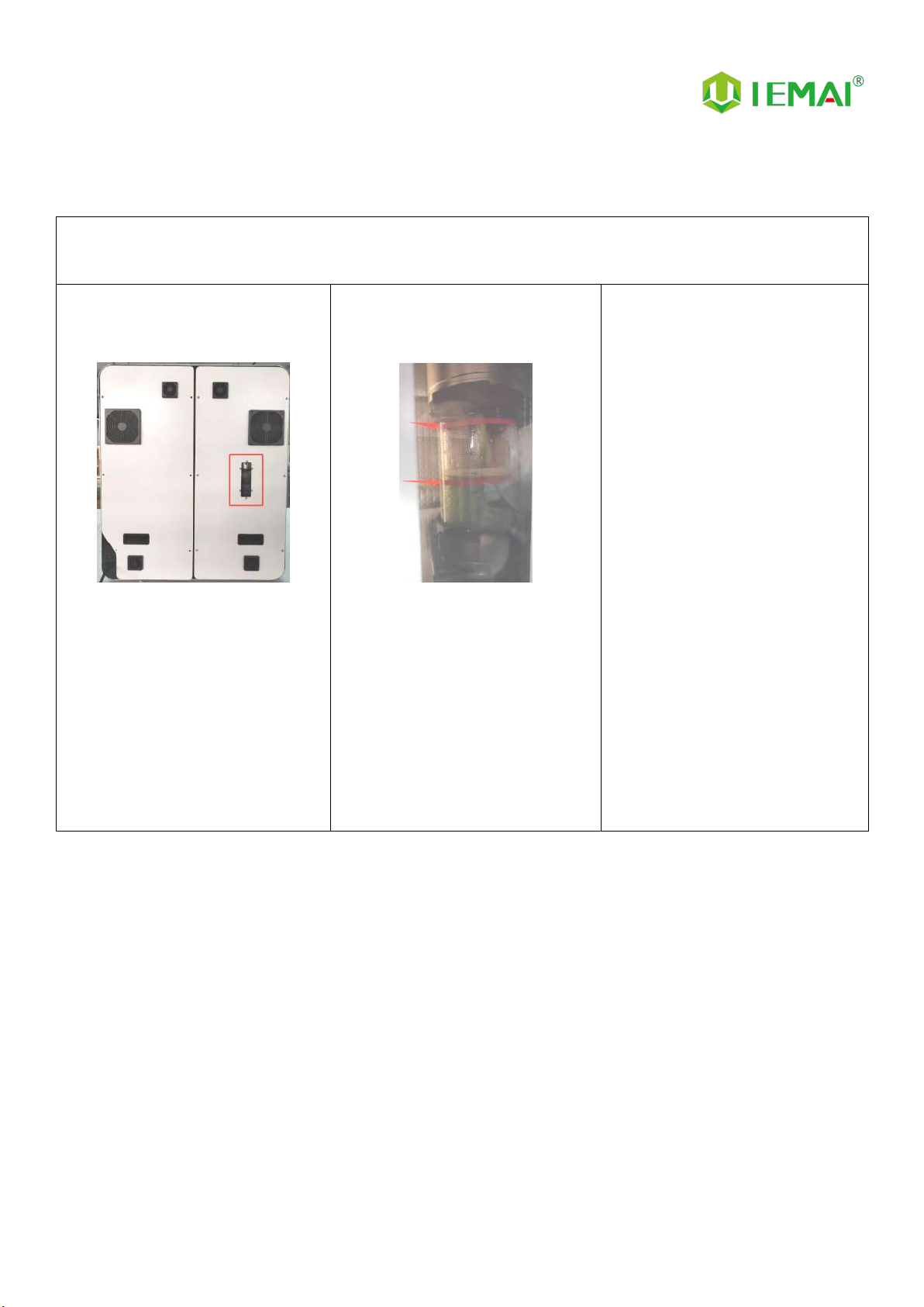
3.2 Check the Refrigerant
02 Check the Refrigerant
Step 1
Shown In the Figure
1. The refrigerant can be viewed in
the window behind the device
Step 2
1. During shutdown, the height of
the normal refrigerant level
should be located between
3.5-6.5 cm, i.e. between the
two red lines as shown in the
figure. If the level is not at the
right position, refer to the
maintenance procedure for
adding refrigerant.
Print More Materials, All For Application
14
3.3 Hardware Check
Step 1
1.Connect the Power of Printer and
Pedestal as shown in figure
Step 2
2.Under normal condition, all lights of
the device are lit as shown in figure
Step 3
3.Manually make XYZ axis move
through screen to observe if it
moves normally as shown in figure
Step 4
1. Control the E1 and E2
extrusion via the touch screen
to see if the left and right
nozzle gears rotate as shown
in the figure
Step 5
1.Through pre-heat via the screen
2.The temperature can be set for the
hot bed, left nozzle, and right nozzle
3.The temperature on the right
represents the set temperature
4.The temperature on the left
represents the actual temperature
5.The recommended hot bed temp
for the first warm-up:50℃±2℃
6.Left/Right Nozzle temp:210℃±2℃
Print More Materials, All For Application
15
4. Print Operation
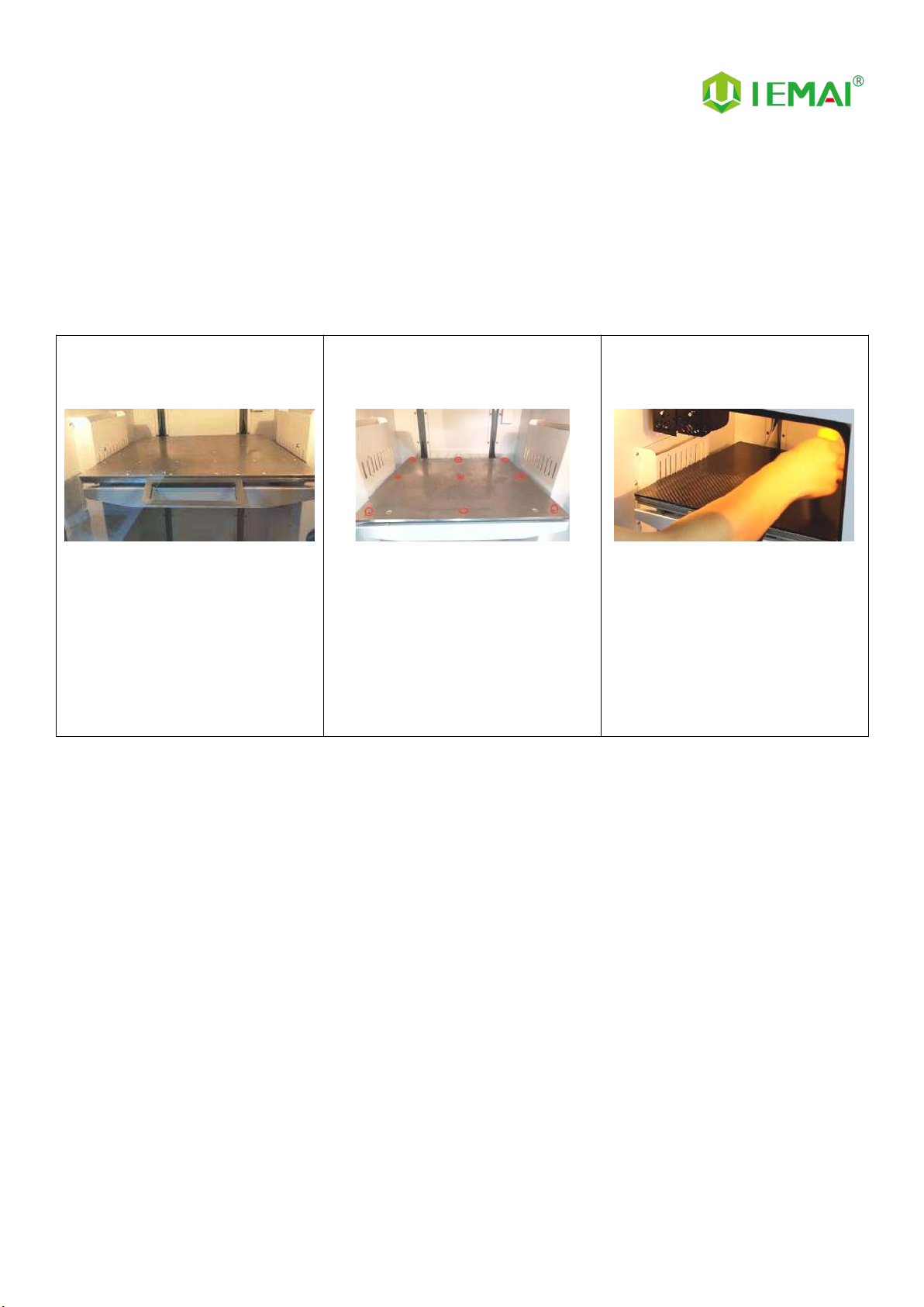
4.1 Use of The Printing Platform
Step 1
1. When you receive the device,
the platform is installed, if you
want to disassemble it, please
hold the front wrench, and pull
it forward to install it, then
align the snap position and
push it inward.
Step 2
1. As shown in the picture for the
platform of the nine positioning
screws will build the platform
positioning slot aligned with the
positioning screws to push
inward can be successfully
installed
Step 3
1. Find the platform glue in the
kit, and after the platform cools
down, apply three layers to the
area to be printed: horizontal,
vertical and diagonal to warm
up.
Print More Materials, All For Application
16
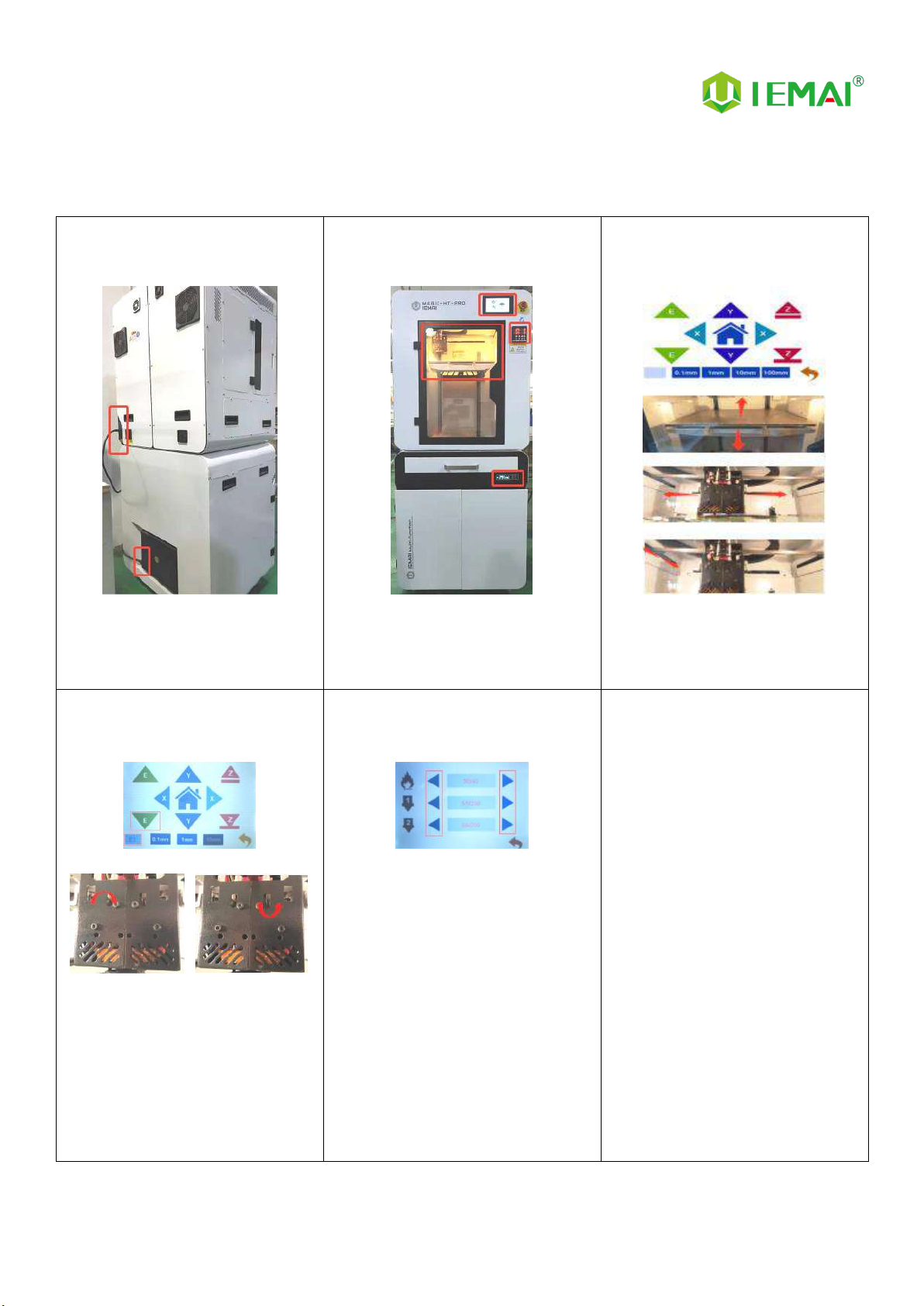
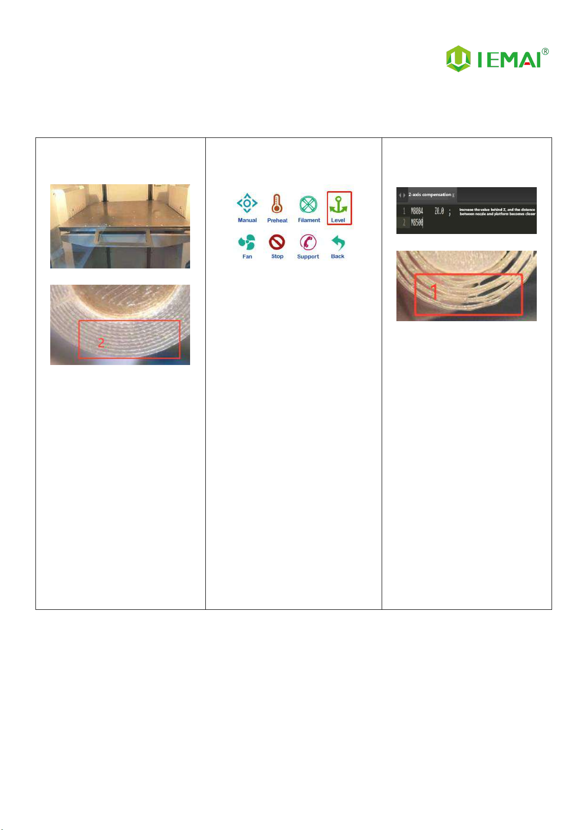
4.2 How to Calibrate
Step 1
1. Initial leveling of the platform
before shipment, if the first
layer is printed successfully at
the first printing, subsequent
leveling steps may not be
performed
Step 2
1. When printing the nozzle is
found to be distant or close to
the platform, but the overall
flatness of the platform has not
changed, that is, the nozzle is
equal to the height of the four
corners of the platform, please
click the screen in the automatic
leveling, wait for the completion
of the 49 points of height
detection error, and then print
test
Step 3
1. When printing the nozzle is
found to be distant or close to
the platform, but the overall
flatness of the platform has not
changed, that is, the nozzle is
equal to the height of the four
corners of the platform, please
click the screen in the
automatic leveling, wait for the
completion of the 49 points of
height detection error, and
then print test.
2. Print the compensation
parameter file once after
modification and burn it to the
machine

Print More Materials, All For Application
17
Step 4
1. If the four corners of the
platform from the height of the
nozzle has a large gap, you
need to adjust the leveling nut
to complete the foundation
leveling, as shown in the figure
using a fixed height object,
respectively, for the four
corners of the platform to
measure the height
Step 5
1. When you can't push the
nozzle manually
2. You can click “ ” unlock the
motor
3. Push the nozzle to the four
corners of the platform to
measure the height
Step 6
1. Leveling by the nuts under the
four corners of the platform,
when the base height of the
four corners is approximately
the same
2. Automatic leveling can
compensate for certain errors
3. Ready for printing

Print More Materials, All For Application
18
4.3 Load/Unload Filament
Step 1
1. Print temperature according to
the material to be loaded
2. Preheat
3. Refer to Step 10 for the
preheating temperature of
different materials
Step 2
1. Straighten the material
Step 3
1. Cut the material to the tip
Step 4
1. Load the material through the
break test port
2. Manually feed it to the gears
Step 5
1. Click to load materials “ ”
2. E1 for the left nozzle, E2 for the
right nozzle
Step 6
1. Till the nozzle appears fine
filament
2. Click “ ” Stop loading
and unloading command
Table of contents
Other IEMAI 3D Printer manuals


