UK
ecomatPanel (CR1300 / CR1301)
9
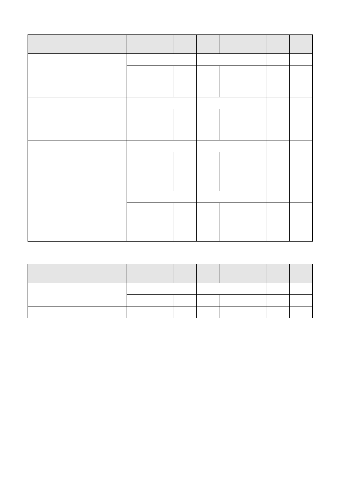
CAN message (J1939) Description Value
KeyPad_J1939_I Drive_4
Byte address: Byte 1, bit 6
Status key 4 0 = key not pressed
1 = key pressed
KeyPad_J1939_I Drive_5
Byte address: Byte 2, bit 0
Status key 5 0 = key not pressed
1 = key pressed
KeyPad_J1939_I Drive_6
Byte address: Byte 2, bit 2
Status key 6 0 = key not pressed
1 = key pressed
8.2 CAN messages for the rotary button
CAN identifier: 0x10FF6487(default)
J1939 PGN: 0xFF64
J1939 priority: 0x4
CAN message (J1939) Description Value
KeyPad_J1939_I Drive_EncVal
Byte address: Byte 3
Number of steps that the rotary
button has been turned since the
last query
0���24
24 = one full turn
KeyPad_J1939_I Drive_EncDir
byte address: Byte 3, bit 5
Rotational direction 0 = clockwise
1 = anti-clockwise
KeyPad_J1939_I Drive_Enter
Byte address: Byte 3, bit 6
Rotary button pressed 0 = rotary button not pressed
1 = rotary button pressed
KeyPad_J1939_I Drive_Left
Byte address: Byte 4, bit 0
Rotary button tilted to the left 0 = rotary button not tilted
1 = rotary button tilted
KeyPad_J1939_I Drive_Right
Byte address: Byte 4, bit 2
Rotary button tilted to the right 0 = rotary button not tilted
1 = rotary button tilted
KeyPad_J1939_I Drive_Up
Byte address: Byte 4, bit 4
Rotary button tilted upwards 0 = rotary button not tilted
1 = rotary button tilted
KeyPad_J1939_I Drive_Down
Byte address: Byte 4, bit 6
Rotary button tilted downwards 0 = rotary button not tilted
1 = rotary button tilted
8.3 CAN messages for the illumination
All CAN messages for the illumination have a data length of 8 bytes and a value
range of 0���255�
CAN message (J1939) Byte
1
Byte
2
Byte
3
Byte
4
Byte
5
Byte
6
Byte
7
Byte
8
LIGHT_J1939_BUTTON1_2_
INTENSITY
CAN ID: 0x18FF7587(default)
J1939 PGN: 0xFF75
J1939 priority: 0x06
key 1 key 2
R G B R G B FF FF