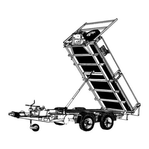
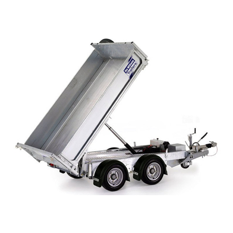
Ifor Williams Trailers Transporta CCT 5221 Instruction Manual

Transporta User Handbook
________________________________________________________________________________
IMPORTANT
If you sell your trailer, please pass this book on to the new owner
________________________________________________________________________________

i
V1.1
lank Page

ii
V1.1
The Transporta CCT 5221 is fitted with brakes and has a MGW (Maximum Gross weight of 3500Kg.
Used correctly and maintained to this handbook, your trailer should give many years of safe and reliable
service. If you are in doubt about any of the instructions, please contact your distributor or our customer care
department.
Please enter the following information for your own records:
Trailer Model: CCT 5221
Variant: LB35
Serial Number:
Date of purchase:
Maximum Gross Weight (MGW): 3500 kg
Payload: 2000kg
Unladen weight: 1500kg
Coupling Key No.:
Door Key No:
Datatag Serial No:
Drawbar security number:
Manufacturers plate
The trailer is fitted with a Manufacturer’s Plate on the right hand side drawbar which will show the following
information:
•The manufacturers name and address details
•The model number
•The trailer serial number
•Maximum gross weight for the trailer

iii
V1.1
Contents
1 - Introduction ........................................................................................................................................................ 1
1.1 - Customer Care ............................................................................................................................................. 1
1.2 - Accompanying Literature ............................................................................................................................. 1
1.3 - Security ........................................................................................................................................................ 2
1.3 - Terminology ................................................................................................................................................. 2
2 - Trailer Plating ...................................................................................................................................................... 3
2.1 – VIN Plate ...................................................................................................................................................... 3
2.2– Drawbar Plate .............................................................................................................................................. 3
2.3 Coupling plates............................................................................................................................................... 3
3 – Safety.................................................................................................................................................................. 4
4 – Towing Vehicle Compatibility............................................................................................................................. 5
4.1 – Gross Train Weight (GTW .......................................................................................................................... 5
4.2 – Imposed Load .............................................................................................................................................. 5
4.3 – Coupling Height ........................................................................................................................................... 5
4.4 –Coupling Type............................................................................................................................................... 5
4.4.1 – 50mm ball ............................................................................................................................................ 5
4.5 – ISO 11446 13pin plug .................................................................................................................................. 5
5 – Coupling ............................................................................................................................................................. 6
5.1 – Coupling components ................................................................................................................................. 6
5.2 - Pre-Coupling up Checks ............................................................................................................................... 7
5.3 - Attaching the trailer to the towing vehicle .................................................................................................. 7
5.3.1 - Coupling Instructions ............................................................................................................................ 7
5.3.2 - Mirrors ................................................................................................................................................ 10
5.3.3 - Final checks before moving off ........................................................................................................... 10
5.4 - Detaching the trailer and parking .............................................................................................................. 10
5.4.1 - Parking the Trailer ............................................................................................................................... 10
5.4.2 - Detaching the Trailer .......................................................................................................................... 11
6 - Driving ............................................................................................................................................................... 12
6.1 - Driving Licence ....................................................................................................................................... 12
6.2 - Towing Speed ......................................................................................................................................... 12
6.3 - Stability .................................................................................................................................................. 12
6.4 - Snaking ................................................................................................................................................... 12
6.5 - Stabilisers ................................................................................................................................................... 12

iv
V1.1
6.6 - Reversing .................................................................................................................................................... 13
7 - 12v Electrics ...................................................................................................................................................... 14
7.1 - Towing Vehicle Power................................................................................................................................ 14
7.2 - Battery Power ............................................................................................................................................ 14
7.2.1 - Battery Charging ................................................................................................................................. 14
7.2.2 - Removing and Replacing the Battery. ................................................................................................. 15
7.3 Modifications ............................................................................................................................................... 15
8 -The Rear Ramp ................................................................................................................................................... 16
8.1 - Rear Ramp Operation ................................................................................................................................ 16
8.1.1 - Understanding your Ramp .................................................................................................................. 16
8.1.2 - Opening the ramp ............................................................................................................................... 17
8.1.3 - Closing the ramp ................................................................................................................................. 18
8.1.4 - Locking the ramp ................................................................................................................................ 18
9 -Tilting the body .................................................................................................................................................. 19
9.1 - Operation of the Manual Hand Pump ....................................................................................................... 19
9.2 - Operation of the Electric Pump system ..................................................................................................... 19
9.2.1 - Manual Operation (back-up system to the electrical pump ............................................................. 21
10 - Loading and Unloading the Transporta .......................................................................................................... 22
10.1 - Petrol/Diesel Fumes ................................................................................................................................. 22
10.2 – Loading .................................................................................................................................................... 22
10.2.1 - Tilting drawbar variant...................................................................................................................... 22
10.2.2 - Untilted or fixed drawbar variant ..................................................................................................... 22
10.3 - Unloading ................................................................................................................................................. 22
11 - Transporta Equipment .................................................................................................................................... 23
11.1 - 12v electric winch .................................................................................................................................... 23
11.2 - Using the Skid extenders ......................................................................................................................... 23
11.3 - The Wheel Stop. ....................................................................................................................................... 23
11.3.1 - Adjusting the wheel stop .................................................................................................................. 24
11.3.2 - Positioning the wheel stop. .............................................................................................................. 25
12 - General hygiene .............................................................................................................................................. 26
12.1 - Safety Precautions ................................................................................................................................... 26
12.1.1 - First Aid ............................................................................................................................................. 26
12.1.2 - Breakdowns ...................................................................................................................................... 26
13 - Maintenance ................................................................................................................................................... 27

v
V1.1
13.1 - Transporta General Maintenance ............................................................................................................ 27
13.1.1 - Exterior Bodywork ............................................................................................................................ 27
13.1.2 - Galvanized Finish .............................................................................................................................. 27
13.1.3 - High Pressure Power Washing .......................................................................................................... 27
13.1.4 - Interior Walls .................................................................................................................................... 27
13.1.5 - Hinges and Catches ........................................................................................................................... 27
13.2 - Hydraulic System Maintenance ............................................................................................................... 28
13.2.1 - Draining the Tank .............................................................................................................................. 28
13.2.2 - Filling the Tank .................................................................................................................................. 28
13.2.3 - Hydraulic Oil Recommendations ...................................................................................................... 29
13.3 - Trailer Running Gear Maintenance .......................................................................................................... 31
13.3.1 - Tyres .................................................................................................................................................. 31
13.3.1.1 - Tyre Repairs ................................................................................................................................... 31
13.3.2 - Changing a Wheel ............................................................................................................................. 31
13.3.3 - Brakes and Coupling ......................................................................................................................... 32
13.3.5 - Leaf Springs ....................................................................................................................................... 34
14 - Electrical Diagrams .......................................................................................................................................... 35
14.1 - 13Pin ISO 11446 Wiring Diagram ............................................................................................................. 35
14.2 - 12v Distribution Box ................................................................................................................................ 36
14.3 - Transporta External Wiring Diagram ....................................................................................................... 37
14.4 - Transporta Internal Wiring Diagram ........................................................................................................ 38
15 - Warranty ......................................................................................................................................................... 39
15.1 - Warranty Claims ...................................................................................................................................... 39
15.1.2 - Guarantee Registration Card ............................................................................................................ 39

1
V1.1
1 - Introduction
Please take the time to read the contents of this manual before using the trailer. It is a good idea when
reading this manual, to take a tour of the trailer with any other people who will be using it.
Make sure the appropriate people understand the procedures for coupling, towing, loading and
maintaining the trailer. By following, understanding and practising the information and procedures in this
manual, the trailer will give you many miles/kilometres of safe travelling.
Some information in this manual reflects UK law and may become outdated. Great care has been taken to
ensure that the information is correct at the time of publication. However, it is the trailers user’s
responsibility to ensure that they fully comply with the law.
We reserve the right to implement changes and improve specifications without prior notice.
Whilst every effort has been made to ensure the accuracy of these instructions, they are intended only as a
guide to the user.
1.1 - Customer Care
If you require any help or advice, please do not hesitate to contact our customer care team:
email [email protected] or telephone 0843 216 7447.
Our business hours are 8am to 4:30pm, Monday to Friday. (Please note that telephone calls to our
Customer Care Department may be recorded for Quality & Training purposes)’
1.2 - Accompanying Literature
Various publications and appliance instruction manuals are supplied with your user handbook. These are to
be read in conjunction with the user manual.
“Towing and the Law” –SMMT ooklet Included with this handbook
Compiled by The Society of Motor Manufactures and Trailers Ltd. There are wide-ranging rules and
regulations to comply with when towing a trailer. This book covers subjects such as the suitability of a
vehicle for towing a particular trailer and the necessity for correct maintenance of tyre and brakes. “Towing
and the Law” has been designed to assist trailer users to ensure that they are complying with the law.
Please note that the information given in “towing and the Law” is subject to change without prior notice.
Great care has been taken to ensure that the information is correct at the time of publication. However, it
is the owner/ user’s sole responsibility to ensure that they fully comply with all legal requirements. Ifor
Williams Trailer Ltd. Will not accept liability for any inaccuracy or incorrectly stated legal requirements.

2
V1.1
1.3 - Security
Your trailer is security marked, but as an added means of assisting the police in making a positive
identification we recommend that you mark the trailer with your postcode or another unique mark.
Transporta trailers are also fitted with Datatag electronic tags for use with Police scanner systems.
If you wish to protect your trailer with a coupling lock or other security device your distributor will be
pleased to advise you of the various devices which are available.
Padlocks can be fitted to the rear ramp.
1.4 - Terminology
Trailer Your new Ifor Williams trailer.
GVW Gross vehicle weight - Referring to the towing vehicle, this is the maximum
allowable weight of the vehicle and its contents.
MGW Maximum Gross Weight - Referring to the trailer, this is the manufacturers stated
maximum for the trailer and its load, often governed by such items as coupling,
tyres etc. although this may have been adjusted downward for one of a number of
reasons.
GTW This is the total weight of the towing vehicle plus trailer plus load, also sometimes
called gross combination weight (GCW).
MAM Maximum Authorised Mass, A new term used in driver licensing regulations, this
has the same meaning as MGW detailed above.
Unladen weight The actual mass of the vehicle (with any accessories shown on the Certificate of
Conformity.
Payload The amount you are allowed to carry, the payload and the unladen weight added
together must never exceed the Maximum Gross Weight.
Imposed load The downward force exerted on the tow ball by the drawbar of the trailer.
Left & Right Are always referred to with regard to forward travel, i.e. viewed from on-board the
trailer with the drawbar visible in front of you.
Vehicle Combination The towing vehicle and trailer combined.
VIN Vehicle Identification Number

3
V1.1
2 - Trailer Plating
Your trailer will have two identification plates which are typically attached to the right hand side of the
drawbar, along with a third plate on the coupling head. The main drawbar plate (the VIN plate contain
important information including the trailers serial number and its max gross weight.
Before towing your Ifor Williams Trailer be sure to check that the vehicle-trailer combination is suitable.
Also ensure your driving licence permits you to tow the trailer / load combination.
2.1 – VIN Plate
1. EC Approval Number -
2. VIN Number (the last 7 digits are the Ifor Williams serial number
3. Maximum Gross Weight (MGW
4. Maximum Permissable Ground load on the first axle
5. Maximum Permissable Ground load the second axle
6. Maximum Permissable Ground load on the third axle (tri-axle trailers only
7. Ifor Williams Model Description
2.2– Drawbar Plate
The drawbar plate contains no additional information useful to the typical user. In the particular case of the
trailer being towed by a Heavy Goods Vehicle the D
c
value may be required.
1. Drawbar Manufacturer
2. Internal Description
3. Internal Description
4. Maximum Gross Weight allowed
5. Theoretical Horizontal Reference Force (D
c
value
6. Maximum static Load
7. Approval number
2.3 - Coupling plates
This contains mandatory information relating to the approval of the coupling alone. It also contains no
information useful to the trailer only

4
V1.1
3 – Safety
THE FOLLOWING POINTS ARE MOST IMPORTANT TO ENSURE SAFE USE OF THE TRAILER
•Ensure the trailer and equipment are serviced and maintained as detailed in this manual
•Never attempt to lift the front of the trailer by hand when coupling the trailer to the tow vehicle or
at any other time. Always use the jockey handle to raise and lower the coupling.
•Use an approved towing bracket and coupling on the towing vehicle. Only use tow-bars and tow-
balls that are approved by the vehicle manufacturer and that have been fitted by his approved
Agent. In case of doubt get the installation checked by the vehicle manufacturers Agent.
•Always observe the limitations on trailer imposed loads given in your towing vehicle’s handbook.
•Never exceed the maximum gross weight shown on the trailer plate.
•Never exceed the legal towing speeds.
•Check tyre pressures before every journey. Correct pressures are shown on a label inside the
trailer. Towing vehicle tyre pressures, especially the rear tyre pressures, are also vitally important.
•Check wheel bolts after first 25 miles of service and subsequently before every journey. (See
section 13.3.2.3 - Fitting Wheels, for wheel bolt tightening details
•Ensure all external lights work before every journey.
•Always connect the breakaway cable to the vehicle tow-bar. Be aware that this has a safety critical
function. Which is, in the event of a separation between towing vehicle and trailer, to first apply
the trailer handbrake, then break itself.
•Always leave the handbrake on or chock the wheels when the trailer is parked. When parking the
trailer for extended periods, it is advisable to chock the wheels and release the handbrake to avoid
the possibility of the brake shoes adhering to the brake drum surface.
•With the trailer coupled to the towing vehicle, the bed of the trailer should be level. It is
recommended, therefore, that provision be made on the towing bracket for adjustments to be
carried out to the towing ball height to allow for various conditions of loading.
•Never load the trailer such that the coupling imposed load exceeds the maximum (150kg for the
trailer or any lower limit specified in the towing vehicle handbook
•Avoid, where possible, uncoupling a loaded trailer. If unavoidable, take great care to ensure that
the jockey wheel is securely clamped and the handbrake is fully applied.
If the trailer is on a slope, chock the wheels as an added precaution.
•Always tie down securely or restrain effectively all loads and carry out regular checks on the
condition of the load during the journey. Be aware that the highest loads occur during braking and
restraint against forward movement is particularly important.
If additional equipment is to be fitted to the trailer which involves any welding, drilling or any structural
modifications to the trailer, approval should be obtained from our Customer Care Department before
commencing work.

5
V1.1
4 – Towing Vehicle Compatibility
Before towing, the first consideration should be whether the towing vehicle is suitable for this trailer. The
following factors should be considered before attempting to tow the Transporta.
4.1 – Gross Train Weight (GTW)
The Selected towing vehicle should have a maximum GTW/GCW (consult the towing vehicle VIN plate
which exceeds the trailer MGW plus the actual laden weight of the towing vehicle.
4.2 – Imposed Load
The selected towing vehicle should have a maximum imposed load capacity equal to at least 4% of the
trailer GTW. In the particular case of Transporta, the imposed load should be kept in the range of between
100kg and 130kg. The selected towing vehicle should be capable of accepting this upper figure.
4.3 – Coupling Height
The trailer needs to be as level as possible when towing. In order to achieve this the vehicle coupling height
should be 400-420mm with the trailer laden. This is taken to the centre of the tow-ball.
4.4 –Coupling Type
4.4.1 – 50mm ball
In most cases your Transporta is fitted with a 50mm coupling head, in this instance you will require a 50mm
tow-ball in compliance with Directive 94/20/EC, ECE R55.
4.5 – ISO 11446 13pin plug
The Transporta is fitted with an ISO11446 13pin plug. This plug not only provides a power supply for the
trailer external lights, but also to power the internal lights as well as charging the on-board battery (if
fitted whilst the vehicle ignition is on.
If your towing vehicle is fitted with a single 7pin socket (12N , a 13/7 pin adaptor is available from your
local Ifor Williams distributor. However please note that in this case the external reversing lights, internal
lighting and battery charging facility will not be powered from the towing vehicle.
Be aware that some towing vehicle manufacturers supply their 13pin sockets with only 7 or 8 powered
pins. As is the case with the 7pin socket above, the external reversing lights, internal lighting and battery
charging will not be powered from the towing vehicle if this is the case. Please contact your local towing
vehicle dealer for advice on how to upgrade your 13pin socket to enable these functionalities.
If your towing vehicle has twin 7pin sockets (12N & 12S an adaptor can be purchased to fully convert your
13pin plug for use with your towing vehicle.

6
V1.1
5 – Coupling
5.1 – Coupling components
Coupling Drawbar & Jockey Wheel:
1. Drawbar
2. Overrun unit (Coupling body
3. Coupling head/Eye
4. Handbrake lever
5. Breakaway cable & clip
6. Lighting cable & Plug
7. Jockey wheel operating handle
8. Jockey wheel ‘R’ Clip
9. Jockey wheel clamp handle
10. Jockey wheel
11. Breakaway cable guide
12. Manoeuvring handle
13. Manufacturers type plate
Coupling head
14. Release button (N/A on eye type
15. Operating handle (N/A on eye type
16. Lock & cover (N/A on eye type
17. Wear indicator tab (N/A on eye type

7
V1.1
5.2 - Pre-Coupling up Checks
efore coupling up always check the following:
1. Check wheel bolts after first 25 miles of service and subsequently before every journey. Torque to:
81 lb ft, 110 Nm, 11 kgm
2. Check tyre pressures before every journey. 95p.s.i. (6.5bar
3. Inspect all wheels and tyres for signs of deterioration or damage.
4. Check the lighting equipment for damage.
5. Ensure all loose articles are stowed securely.
6. Check all doors are closed and secured.
7. Ensure floor grommets are closed.
8. Ensure external power cables are disconnected and stowed correctly.
9. Check the battery is secured with its strap and the isolation switch is in the on position for charging.
10. Ensure ramp is fully secured.
If there is no breakaway cable fitted to your trailer, or if it or any other part of the coupling, draw tube
or handbrake assembly appear to be damaged or missing parts - DO NOT TOW !
5.3 - Attaching the trailer to the towing vehicle
•It is recommended that a minimum of 2 people work together when hitching up the trailer to the
tow vehicle.
•When reversing ensure any pedestrians and your assistant are visible at all times.
reakaway cable
The breakaway cable is designed to operate the handbrake if the trailer becomes detached from the
towing vehicle. It will then detach itself by the spring ring opening out.
After use, the cable and spring ring should be replaced to ensure correct future operation.
5.3.1 - Coupling Instructions
Whenever possible, both trailer and towing vehicle should be on level ground.
5.3.1.1 - 50mm Ball Couplings
1. Check the condition of the breakaway cable. If frayed or kinked, replace before using trailer.
2. Check that the ball is clean, and the coupling head cup is well greased.
3. Ensure that the trailer handbrake is fully applied.
4. Disengage the jockey wheel R clip.
5. Ensure that the jockey wheel clamp handle is tight and, by turning the jockey wheel jack handle,
raise the coupling to a height greater than that of the coupling ball.

8
V1.1
6. Reverse the towing vehicle up to the trailer so that the coupling head is directly over the towing
ball. Fully apply the towing vehicle handbrake and stop the engine.
When reversing your vehicle towards the trailer use an assistant to direct you and take great care to avoid
striking the coupling head which could cause damage to towing vehicle and trailer coupling.
7. Attach the breakaway cable to the attachment eye or strong point of the towing bracket, either
directly to a dedicated loop or eye.
8. Remove the protective cap and unlock the coupling head (turn the key anti-clockwise .
9. Press the release button on the coupling head and lift the handle. Lower the coupling head by
means of the jockey wheel jack handle until the
coupling head is in place over the towing vehicle
ball, and release the handle.
10. Check the ball is fully engaged into the coupling
body.
11. Check the release button has clicked back into
place.
12. Test that the ball is engaged by attempting to
lift the coupling off the ball with the jockey
wheel.
13. Retract the jockey wheel until it is fully wound
up.
14. Line up the anti-rotation pin on the jockey forks
with the notch on the stem and wind the wheel
further up so it can no longer rotate.
15. Hold the top of the jockey wheel assembly and
release the clamp.
16. Taking care lift the jockey assembly fully up,
positioned well clear of the brake linkage and
inside the drawbar channel with the wheel
trailing rearwards.
17. Clamp the jockey wheel in place and engage the
jockey wheel R clip to prevent lowering in
transit
18. Attach the electrical plug to the towing vehicle’s
socket ensuring there is enough slack in the
cable for the trailer to correctly negotiate tight
turns, without the cable dragging on the road.
Check that all the lights are operating correctly.

9
V1.1
19. Release the trailer handbrake.
20. Check the breakaway cable cannot drag along the ground and cannot become taut during normal
use.

10
V1.1
5.3.2 - Mirrors
You are required to be able to see the rear corners of the trailer in your rear view mirrors. If you cannot,
use add on mirror extensions.
5.3.3 - Final checks before moving off
Check that you are displaying the correct registration plate for the towing vehicle you are using, if the
trailer is being used on public roads.
Any load should be securely fixed.
If corner steadies are fitted check that they are raised and that any doors or ramps are correctly closed.
Finally release the trailer handbrake and you are ready to move off.
Passengers
Passengers are forbidden to ride in a trailer at any time.
5.4 - Detaching the trailer and parking
5.4.1 - Parking the Trailer
Before detaching the trailer from the towing vehicle, you should choose the area where the trailer is to
remain with care. Ideally the trailer should be parked on firm level ground to safeguard against the trailer
rolling or sinking into the ground.
Where you have no option but to park on soft ground, the trailer should rest on suitable scaffold type
boards. Always apply the handbrake when the trailer is parked independently of the towing vehicle and
chock the wheels on sloping ground.

11
V1.1
5.4.2 - Detaching the Trailer
Except in an emergency, you should never unhitch a laden trailer!
If you have reversed the trailer into a parking position, pull forward a small amount so that the trailer
brakes come out of auto-reverse mode, apply the towing vehicle and then the trailer handbrake.
1. Return to the towing vehicle, release the (towing vehicle’s handbrake and allow the towing vehicle
to move forward slightly this allows the compressed draw tube to re-extend to its normal position,
otherwise uncoupling will be difficult.
2. Re-apply the towing vehicle handbrake and switch its engine off.
3. Check once again that the trailer handbrake is fully applied, especially if the trailer was reversed to
its parking position as there may still be some ’slack’ in the braking system.
4. Detach the trailer’s lighting cable from the towing vehicle’s socket and attach it to the parking
socket provided on the trailer coupling.
5. Release the jockey wheel clamp, lower the jockey wheel to the ground and securely tighten the
clamp
6. Disengage the R clip and turn the jockey wheel operating handle anticlockwise until it just begins to
take the weight of the drawbar.
7. Release the coupling head as described under 2.3.1.1 coupling the trailer, continue turning the
jockey wheel until the coupling head is raised clear of the ball. (For eye couplings, remove the pin
from the towing jaw following the towing jaw manufactures instructions.
8. Finally disconnect the breakaway cable from its attachment point. Don’t forget to re-fit your tow
ball cover to keep the ball in good condition and protected from the effects of the weather.
IMPORTANT –Never detach the breakaway cable before uncoupling the trailer.
If the trailer is to be parked for a long period of time it is advisable that the wheels are chocked and the
handbrake released, this minimises the possibility of brake linings sticking to the drums.

12
V1.1
6 - Driving
6.1 - Driving Licence
Only drivers with a full driving licence with B+E categories are allowed to tow this trailer.
6.2 - Towing Speed
The maximum speed limit under UK regulations is 60mph.
NOTE: The 60mph limit is allowed on motorways and unrestricted dual carriageways only. On other
unrestricted roads the limit is 50mph. If your vehicle & trailer combination is over 7500Kg combined MAM
speeds are further restricted to 50mph on dual carriageways and 40mph on other roads.
6.3 - Stability
All our trailer models are of a well balanced design and should be exceptionally good towers.
The common causes of poor stability include:
a. Worn springs or loose suspension fixings on the towing vehicle.
b. Towing vehicle springs too soft.
c. Insufficient nose weight.
d. Nose of the trailer either too high or too low, due to incorrect height of the tow ball.
e. Insufficient tyre pressures, towing vehicle and trailer.
f. Unsuitable towing vehicle.
6.4 - Snaking
This is a term used to denote an unstable towing vehicle and trailer combination where the trailer ‘weaves’
from side to side often causing a similar swaying movement in the towing vehicle itself.
Causes:
1. Unsuitable or unbalanced Vehicle Combination.
2. Incorrect loading or weight distribution.
3. Excessive speed, especially downhill.
4. Side winds.
5. Overtaking.
6. Being overtaken by a large fast moving vehicle.
7. Erratic driving.
8. Insufficient tyre pressures, tow vehicle and trailer.
9. Incorrect vehicle hitch height.
10. Insufficient nose weight.
On the road
If you do find your Vehicle Combination snaking, try to keep the steering wheel in a central position as
far as possible, decelerate and avoid braking if possible.
6.5 - Stabilisers

13
V1.1
A stabiliser should never be used to try to improve a trailer/towing vehicle combination that has poor
stability as instability may occur at higher speed.
However, a good stabiliser can make an acceptable trailer/towing vehicle combination more comfortable
and easier to handle.
6.6 - Reversing
All trailers are fitted with auto-reverse braking systems. Manual reverse catches are available as optional
extras for use in particularly adverse conditions, eg. reversing up a slippery incline, where the slight drag
present in the auto-reverse brakes may otherwise cause the wheels to lock.

14
V1.1
7 - 12v Electrics
The 12v electrical system is powered by either an auxiliary battery located in the front of the trailer or
through the permanent feed from the towing vehicle. These feed power to the 12v distribution box located
in the front compartment, which then distributes power via circuit breaker trip switches to the lighting and
the aux power socket.
When leaving the trailer in storage turn the battery isolator switch to the OFF position to prevent
accidentally discharging the battery.
7.1 - Towing Vehicle Power
Power from the towing vehicle is only supplied to the trailer when the engine is running. This power is only
used to charge the battery (with the battery isolator switch in the on position when travelling. When the
towing vehicle is providing power to the trailer, power to the 12v output circuits is cut off via a relay. This is
a legal requirement, so any interference from the trailer electrical appliances cannot interfere with the
towing vehicle, although the internal lights are EM approved.
You will need to turn the towing vehicles engine off before you can use 12v power inside the trailer and if
at any time you turn on the engine back on, power in the trailer will be cut off.
7.2 - attery Power
The auxiliary battery must be placed inside the battery box provided to contain accidental acid leaks and
must be used at all times. This box will hold a battery of up to 80 amp hour’s capacity, depending on the
battery dimensions. The battery and box should be secured with the strap to prevent movement when
towing. The battery box lid contains the main fuse and the isolation switch.
A gas vent hose is fitted to the battery and exits through the trailer floor. This vent hose must be fitted
at all times to vent away hydrogen gas and to isolate the gas from the electrics.
7.2.1 - attery Charging
Whilst the trailer is being towed the towing vehicle supplies power to the trailer to charge the battery. If
battery charge is low and your journey is short it is unlikely the battery will be fully charged at your
destination. As state of charge is unknown it is advisable to fully charge the battery before each trip. Avoid
running the battery flat as this will shorten the life of the battery.
To charge the battery:
1. Turn off all 12V systems.
2. Disconnect the electrical connector to the towing vehicle.
3. Turn off the battery isolation switch located on top of the battery box.
4. Un-strap the battery box and lift off the lid.
5. Connect and charge with a suitable battery charger and follow the chargers instructions.
6. After charging replace the lid, strap up the battery box and turn the isolation switch back on.
Table of contents
Other Ifor Williams Trailers Utility Vehicle manuals
Popular Utility Vehicle manuals by other brands

Cushman
Cushman Turf Truckster 84069 Parts & maintenance manual

Landoll
Landoll 900D Series Operator's manual

Westward
Westward Go-4 XTR Operator's manual
Club Car
Club Car Carryall I 1999 owner's manual

Etnyre
Etnyre Street Flusher operation, maintenance, parts and safety manual

Landoll
Landoll 340 Operator's manual
