Ifor Williams Trailers TT85G User manual

These instructions are provided to help you to get the best possible service from your trailer.
To ensure that the trailer is used safely, we strongly recommend that the instructions are read
by all users and all the recommendations followed. This also applies to the enclosed user’s
manual.
Misuse may invalidate warranty
Please enter the following information for your own records:
Trailer Model:
Serial Number:
Drawbar Security Number:
Coupling Security Key No.:
In addition to this booklet, the following items should be in the document bag:
1. One route card (with trailer serial number and specification)
2. One Guarantee Registration Card (unless the distributor completed the card for you)
3. One Ifor Williams Trailers sticker
4. One leaflet - battery details & warranty (Optional fitting)
Guarantee Registration Card
It is important that the Guarantee Registration Card supplied with the trailer is completed and
returned without delay, not only to ensure that the guarantee is validated, but also to enable
us to assist the police in returning your trailer to you should it be stolen. It also allows us to
contact you in the event of a recall.
BRITAIN’S LEADING TRAILER
MANUFACTURER
FM 13224
FM13224
IMPORTANT
If you sell your trailer, please pass on this booklet and the main
user’s manual to the new owner
C95030 Issue 4: January 2006
TIPPING TRAILERS
TT85G, TT85GE, TT105 & TT126
OPERATOR MANUAL

2Tipping Trailers
Operator Manual
SPECIFICATIONS
TT85G TT85GE TT105G TT126G
Maximum Gross Weight 2600 kg 2600 kg 3500 kg 3500 kg
(trailer and load)
Unladen Weight 640 kg 680 kg 966 kg 1150 kg
(trailer complete with standard equipment)
LEGAL NOTICE
Whilst every care is taken to ensure that the information in this manual is correct, no liability can
be accepted for any loss damage or injury caused by any errors in, or omissions from, the
information given.
TT126

Tipping Trailers 3
Operator Manual
GALVANIZED FINISH
Galvanized coatings should not be considered as aesthetic or cosmetic finishes. They are
present as barriers to prevent corrosion of steel components and also afford a great deal of
sacrificial protection should small, localised surface damage occur.
The hot-dip galvanising process produces a coating which is bonded metallurgically to the steel:
a unique feature in coating processes. It is the most widely used method of protection against
corrosion and has the added benefit of giving excellent wear resistance.
During the initial months of exposure of a galvanized coating to the atmosphere, the outer
surface weathers by reacting with oxygen, moisture and carbon dioxide in the atmosphere,
converting the original shiny surface colour to a matt dull grey protective coating. During this
period it is particularly important that any deposits of corrosive substances such as road salt,
fertilizer and slurry are removed by immediate washing. This will allow the galvanized coating to
dry out, encouraging the development and retention of the protective coating. Failure to do so
will lead to discolouration and unsightly staining of the surfaces.
Once formed, the weathered galvanized coating should provide protection against corrosion
throughout the trailers life.
WASHING
Regularwashingwithasolutionofwaterandmilddetergentsuchascarwashwillhelptoprolong
the surface finish of plated and painted components.
This is particularly important if the trailer is used on salt-treated roads, in coastal areas, is heavily
soiled or is used to carry corrosive substances such as fertilizers. In these cases, the trailer
should be thoroughly washed down after each use.
If using a pressure washer, care should be taken to avoid training the high pressure spray onto
electrical components or decals for extended periods or at close range.

4 Tipping Trailers
Operator Manual
LOADING & UNLOADING
The trailer should be positioned on level ground.
Except in emergencies, loading and unloading should be carried out
with the trailer attached to the towing vehicle. If for any reason you
havetodosowiththetrailer detached, take greatcareto ensure that
the jockey wheel is securely clamped and the handbrake is fully
applied before proceeding.
If the trailer is fitted with propstands (optional) these should be
lowered and securely clamped (see section on use of loading skids
for details)
If the trailer is on soft ground it may be necessary to provide
additional support under the jockey wheel to prevent it from sinking
into the ground.
USE OF THE SAFETY PROP
DO NOT ENTER, LEAN INTO OR REACH INTO THE AREA
UNDER THE RAISED BODY UNLESS THE PROP IS LOCKED IN
THE SAFETY POSITION AS SHOWN:-
Fig. 1 prop in safety position
Fig. 2 prop in safety position (chassis end)
Fig. 3 prop fixed under body in transport position
TIPPING THE TRAILER BODY
DO NOT LEAVE THE TRAILER UNATTENDED WITH THE BODY
RAISED UNLESS THE SAFETY PROP IS IN PLACE.
It is recommended that new users practice operating the tipping
mechanism with the trailer empty to ensure familiarity with the
controls.
The trailer should be positioned on flat, level ground.
Keep the area around the trailer clear during the tipping
operation either with the help of an assistant or using road cones.
Standing to one side of the rear of the trailer, slide the retaining ring
upwards to release the lever and lower the lever. Repeat for the
other side to release the tailboard. (Fig.4)
Operation of the electric pump system
The tipping system comprises an electro-hydraulic pump powered
by an on-board heavy duty 12V battery to operate a lifting ram (fig 5)
The pump is operated from a remote control switch pad on a
detachable lead. (fig 7) An isolator switch with removable key is also
provided.
Fig.1
Fig.2
Fig.3
Fig.4
.

Tipping Trailers 5
Operator Manual
TILTING THE TRAILER BODY (continued)
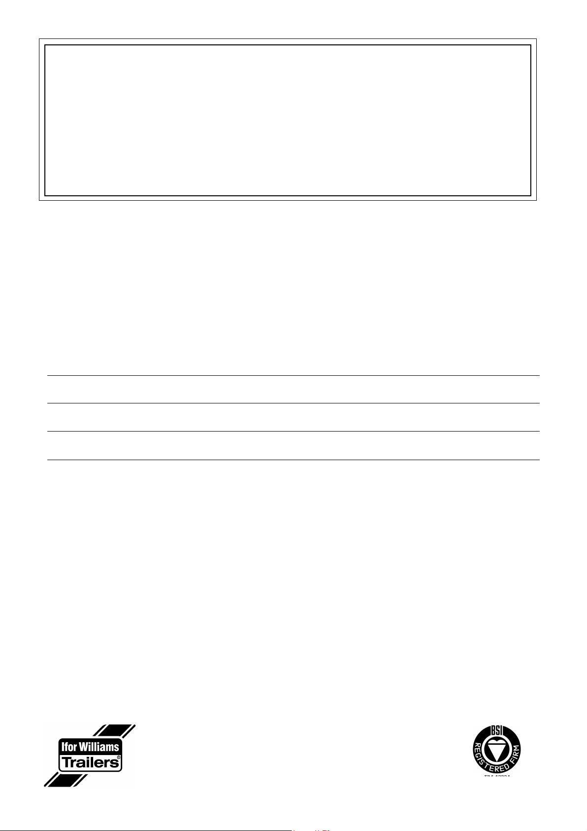
Connect the remote control lead to the socket on the side of the
pump. * (fig 6) Insert the key into the isolator switch and turn
clockwise through 90 degrees to switch on.
After checking that the rear of the trailer is clear, operate the ‘up
arrow’ button on the remote control to tip the trailer body.
As the load starts to move, release the button and operate again in
short bursts to release the load slowly. It may be necessary to move
the trailer forward before the full load has been released to avoid the
load coming in contact with the rear of the trailer. Lower the body
slightly to hold the load back before moving the trailer forward.
To lower the body, operate the ‘down arrow’ button until the body is
in the required position. To return the trailer bed to the horizontal
position, ensure that the area between the body and chassis is clear
of obstructions and lower fully. To ensure that the body cannot be
accidentally raised, disconnect the remote control lead plug from the
socket (a straight pull).
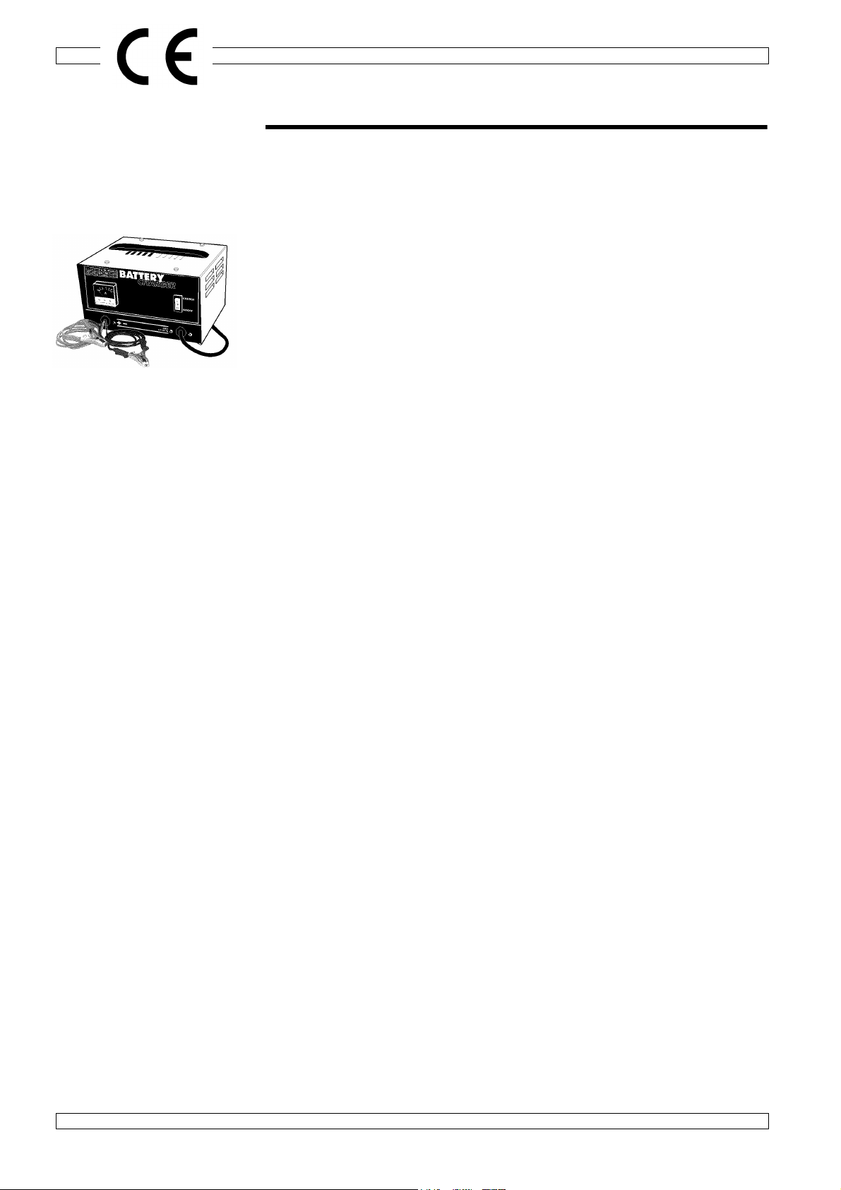
During normal operation the ‘Green’ LED lamp on the remote control
will be lit. If the ‘Red’ LED lamp lights it will indicate that the battery
charge is low - i.e. below 9V. See also page 8 - battery indicators.
Turn the isolator key anti-clockwise through 90 degrees to switch off,
and remove the key.
Manual Operation (back-up system to the electrical pump)
Operation
Check that the rear of the trailer is clear.
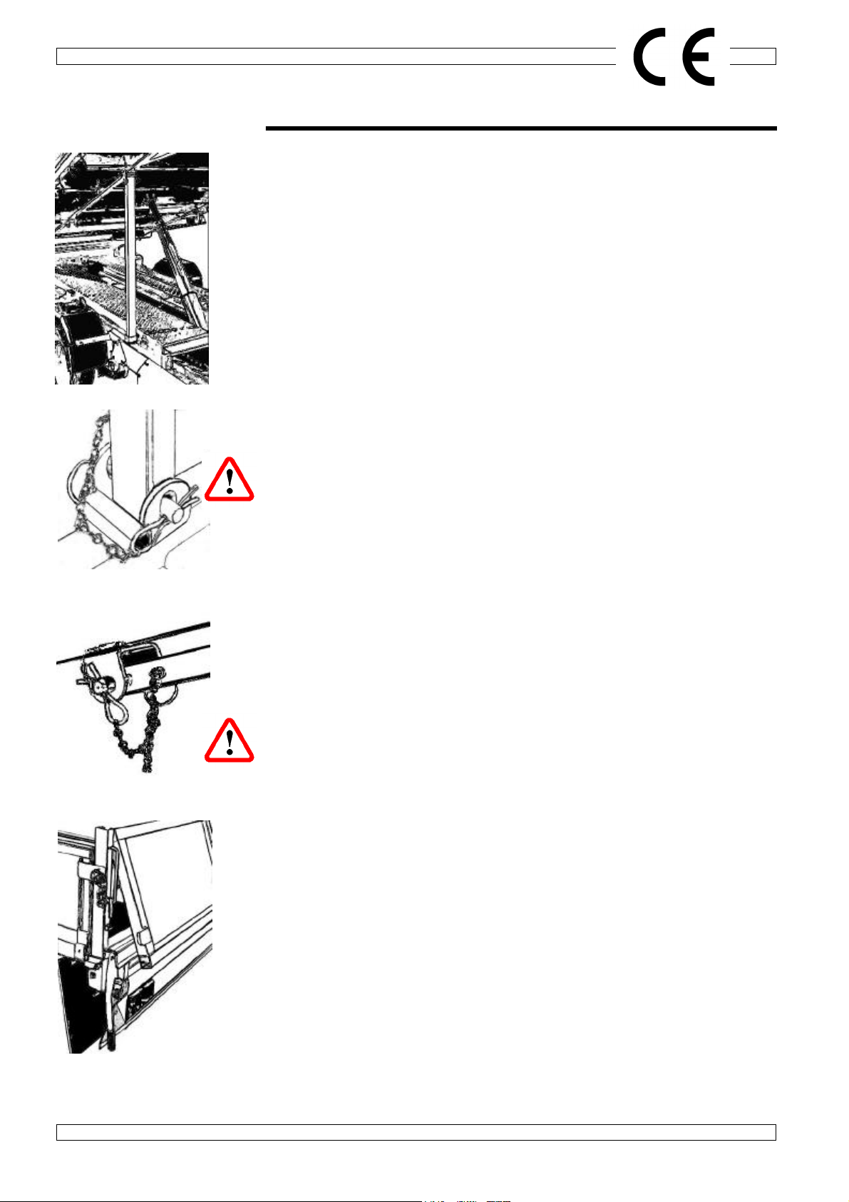
Check that the manual release valve is closed and insert the handle
into the socket. After checking that the rear of the trailer is clear,
operate the manual pump lever to tip the trailer body.
To lower the body, check that the area between the body and chassis
is clear of obstructions and open the valve slowly. Control the rate of
descent by opening and closing the valve as required.
* Users should note that the remote control unit supplied is generally
splash-proof, although it is not fully waterproof. It should never be
submerged and should be removed from the trailer when not in use
to avoid damage and possible erratic operation.
If a control unit has been accidentally submerged or is otherwise
damaged it should be taken out of service until it can be fully checked
or ideally replaced with a new unit.
Fig.8
Fig.6
Fig.7
Fig.9
Fig.5
Slide pump handle into receiver
Behind front pump plate
Red & Green
LED Lamps
Up
Down
Manual operating handle
Manual release valve
Pump handle socket
Oil reservoir waterproof
filler cap Pump
Electrical remote
control connector
Isolator switch
and key

6 Tipping Trailers
Operator Manual
TIPPING THE TRAILER BODY (continued)
TT85G (Manual Pump)
The tipping system comprises a manually operated hydraulic pump
to operate the lifting ram (fig 10).
Operation
Check that the release valve is closed. After checking that the rear
of the trailer is clear, operate the manual pump lever to tip the trailer
body.
It may be necessary to move the trailer forward before the full load
has been released to avoid the load coming in contact with the rear
of the trailer. Lower the body slightly to hold the load back before
moving the trailer forward.
To lower the body, check that the area between the body and
chassis is clear of obstructions and open the release valve slowly.
Control the rate of descent by opening and closing the valve as
required.
Fig.10
Release valve

Tipping Trailers 7
Operator Manual
LOADING SKIDS (TT105G and TT126G only)
Removing skids
The skids are stowed under the trailer body and are removed from
the rear of the trailer. It is strongly recommended that any lifting or
positioning of the skids is carried out by two persons. (Each skid
weighs approximately 40kg).
1. Lift the spring ring and withdraw the linch pin. Lift the handle to
release the skid retainer clamp. (fig 11)
2. Move the handle to the left to remove the right skid or to the
right to remove the left skid. (fig 12)
3. Lift the rear of the skid and slide out slightly. (fig 13)
4. Slide the skid out. It is prevented from sliding all the way out by
a stop. Lift the front end of the skid clear of the stop and slide
out slowly.
5. Hook the skid onto the rear channel in the required position (fig
14)
Replacing skids
1. Ensure that the skid retainer clamp handle is positioned on the
opposite side to the skid you are replacing and slide the skid
back into place. To prevent injury, keep fingers and hands clear
of the underside of the skid before the skid reaches the stowage
position.
2. When both skids are in place, slide the clamp handle to the
central position, locate in the receiver bracket and replace the
linch pin as shown in fig 11.
Use of loading skids
Extreme care should be exercised when using loading skids
•Carry out loading and unloading on level, firm ground.
•Always use the prop stands provided.
•Have an assistant on hand to guide you.
•Ensure that the skids are positioned correctly, with the lower
ends on firm, level ground, parallel with the trailer and in line with
the centre of the tyres of the vehicle to be loaded/unloaded and
that the skid top angles are in contact with the trailer rear cross
member over their full width.
•Your assistant should keep well clear during loading/unloading.
•Take your time and constantly check that the vehicle is correctly
positioned.
Fig.14
Fig.12
Fig.13
Fig.11
1
2

8 Tipping Trailers
Operator Manual
BATTERY
TT126G, TT105G & TT85GE (electric pump)
The battery fitted is completely maintenance free (apart from
charging)
When working on or near the battery, observe the following safety
precautions:
EXPLOSIVE GAS
DO NOT SMOKE. AVOID CONTACT WITH SPARKS OR FLAMES
CONTAINS SULPHURIC ACID
AVOID SKIN & EYE CONTACT
“MAGIC EYE” ‘State of battery’ indicator
(automatic built in hydrometer)
Colour: Green Satisfactory state of charge > 65%
Black Battery requires charging < 65%
Yellow / Clear Electrolyte level low *
* When the electrolyte level becomes low, do not use the battery
and also check the electrical circuit of the system. The battery must
be replaced via the manufacturer or their agent as shown on the
enclosed manufacturer’s leaflet.
The battery is warranted by the manufacturer against defects in
materials or workmanship for one year - the full details of which are
shown on the accompanying leaflet.

Tipping Trailers 9
Operator Manual
BATTERY (continued)
Battery Charging
Battery Charger Selection:
A nominal 12 volt charger rated as follows, is required to maintain
the battery at optimum performance.
Battery capacity in Charger size
Ampere hours Rating in Amperes
102Ah(as fitted) 10 to15A or 20A
The selection of the correct charger rating for your battery size is
important to reduce the risk of premature battery failure:
A charger which is under-sized will not fully recharge the battery.
Thiswillresultin a steady reduction of the available battery capacity,
the inability of the battery to complete a normal service cycle, and
eventually irreversible damage leading to battery failure.
A charger that is over-sized can, under certain circumstances, lead
to potential hazardous situations (a: formation of an explosive
gaseous mixture and b: acid spillage - leading to unchargeable dry
cells and exposed acidic fluids), and early battery failure.
Battery Health
Whilst batteries which are not fully charged may still give reasonable
performance, the effect of never allowing the batteries to be
completelyrechargedwillbe agradualreductioninperformanceand
reduced battery life.

10 Tipping Trailers
Operator Manual
HYDRAULIC SYSTEM MAINTENANCE
1. Wipe all external surfaces of the pump and reservoir tank to
remove dirt, dust and oil residue.
2. Inspect unit for leaks and rectify as necessary.
3. Clean reservoir filler cap, remove and renew if cap and / or seal
is damaged. Check oil level and replenish with clean hydraulic
oil.* This should preferably be carried out with actuator (and
thus the body ram) at minimum stroke, i.e. with the trailer body
down. The oil should be approximately 25mm (1”) from the top
of the reservoir tank when full.
4. Fully replace the hydraulic oil at intervals depending upon the
severity of the duty and environment conditions:
Very dirty, dusty and damp: 6 months to 1 year.
Otherwise, in more favourable conditions: Approx. 2 yearly.
Draining the Tank
With the body fully lowered, remove the main pressure supply hose
from the ram (fig 15) and dip into a suitably sized and positioned
container or oil drum. Switch on the electrical operating system (or
operate the manual pump) to pump the oil into the container.
Continue until the oil flow virtually ceases.
DO NOT RUN THE PUMP FOR LONGER
THAN IS NECESSARY WHEN THE TANK
IS APPROACHING EMPTY
Filling the Tank
Use clean, filtered oil of the correct grade. Use a filter unit with a
filtration level of 25 microns (25 µm) or better.
Use only clean jugs and funnels.
CONTAMINATION OF HYDRAULIC OIL ACCOUNTS FOR THE
VAST MAJORITY OF HYDRAULIC SYSTEM FAILURES
Connect the hose to the ram but do not tighten.
Fill the tank to the level mark.
Bleed the system by operating the motor briefly (or operate the
manual pump) whilst observing the release of air from the hose
connection on the ram. As soon as there is no sign of air escaping,
tighten the connector. Check the oil level and top up if necessary.
Main hydraulic
pressure supply
hose connector
* Oil Specification for the
Fenner / SPX Power Pack
Fenner recommend
SHELL TELLUS 37
or it’s equivalent for
temperatures between -
18oCand +70oC. This
should cover most normal
applications.
See pages 11 & 12 for
appropriate graphs
Fig.15

Tipping Trailers 11
Operator Manual
HYDRAULIC SYSTEM MAINTENANCE (Continued)
HYDRAULIC OIL RECOMMENDATIONS
Mineral oil with a viscosity range from 6 to 450 centistokes at normal working temperature.
The following oils are recommended for use at temperatures between -20ºC and +60ºC.
SupplierGrade Pour Point Viscosity in Centistokes
ºC @0ºC @40ºC
B.P.Trading HLP 32 -33 ---- 15
HP 32 -54 ---- 15
Burmah Castrol Hyspin VG 15 -39 117 15
Hyspin AWS 15 -39 117 15
Hyspin AWH 15 -51 82 15
Esso Nuto H 15 -35 95 14
Nuto HP 15 -35 95 14
Univis J 13 -59 50 15
ELF Sternol Albatross -40 77 15
Gulf Oil Harmony 15 AW -30 93 14
Lorco HT15 -40 90 14
FVT 15 -40 85 14
Mobile Oil 11 -45 87 17
Shell UK Oil Tellus T 15 -51 75 15
Total Oil GB Azolla 15 N -30 100 15
Equivis VG15 -51 82 15
Where the temperature is constantly below -10ºC, please consult your oil consultant or supplier.
See page 12 for oil temperature graph.

Tipping Trailers 12
Operator Manual
HYDRAULIC SYSTEM MAINTENANCE (Continued)
Oil viscosity
Temperature limits are based on maximum viscosity of 1000 centistokes (5000 SSU)
and Minimum viscosity of 15 centistokes (80 SSU)
-60 -40 -20 0 20 40 60 80 100
Oil Temperature oC
Oil Temperature oF
-100 -50 050 100 150 200
UNIVIS J25
MIL-5506
SAE 15
ISO VG 22
SAE 10
ATF
SAE 5W20
SAE
SAE 10W30
SAE 10W40
SAE 20
MAXIMUM PUMP
OPERATING TEMP

Tipping Trailers 13
Operator Manual
TYRES
Tyres must be maintained at the pressures indicated below. Under-inflation will adversely affect
handling and fuel consumption and will lead to premature wear. If seriously under-inflated, a tyre
will overheat and fail very rapidly.
When renewing tyres, always ensure that you purchase a tyre of the same size and load/speed
index rating. Different makes or models of tyres of the same size can have widely differing load/
speed index ratings and inflation pressures. Using tyres with a lower rating can be dangerous. If
in doubt, ask a tyre distributor or our technical department.
Tyre Fitments
Load /Speed Index - Pressure (Cold)
TT85G & TT85GE
165R13C 8PR (tubeless) 94/92N 65psi / 4.5 bar
TT105G & TT126G
185/60R12C (tubeless) 104/101N 95psi / 6.5 bar
The maximum gross weight figure given on the trailer plate is always equal to or less than the
approved maximum load for the tyres at 60mph multiplied by the number of tyres on the trailer.
Other maximum load figures are marked on some tyres. These do not apply to the UK or Europe
and should be disregarded
Tyre Repairs
Punctures should be inspected and repaired by a specialist tyre distributor. Do not fit tubes to
tubeless tyres as this can lead to a “blow out” in the event of a further puncture. If the tyre is too
severely damaged for a repair to be carried out the tyre must be replaced.

Tipping Trailers 14
Operator Manual
NOTES

Tipping Trailers 15
Operator Manual
NOTES

Whilst every care is taken to ensure that the information in this manual is correct, no liability
can be accepted for any loss, damage or injury caused by any errors in, or omissions from,
the information given.
Ifor Williams Trailers Ltd., Cynwyd, Corwen, Denbighshire, LL21 0LB, UK
This manual suits for next models
3
Table of contents
Other Ifor Williams Trailers Utility Vehicle manuals
Popular Utility Vehicle manuals by other brands

Muck-Truck
Muck-Truck Power Barrow PRO MKI Operations & parts manual

Polaris
Polaris RANGER 570 2017 Owner's manual for maintenance and safety

Taylor-Dunn
Taylor-Dunn B0-248-48AC Operation, t roubleshooting and replacement parts manual

Craftsman
Craftsman ZTS 7500 Operator's manual

SunL
SunL SLGK-150 user manual

Aero
Aero PowerLock installation instructions