Ifor Williams Trailers CT166G User manual

Tilt-Bed Trailers 1
C95055 Issue 1 06/02
OPERATOR MANUAL
TILT-BED TRAILERS
CT166G, CT167G, CT166GA and CT167GA
These instructions are provided to help you to get the best possible service from your trailer.
To ensure that the trailer is used safely, we strongly recommend that the instructions are read
by all users and all the recommendations followed. This also applies to the enclosed booklet
"General Operation and Maintenance".
Misuse may invalidate warranty
Please enter the following information for your own records:
Trailer Model:
Serial Number:
Coupling Security Key No.:
In addition to this booklet, the following items should be in the document bag:
1. One route card (with trailer serial number and specification)
2. One Guarantee Registration Card (unless the distributor completed the card for you)
3. One Ifor Williams Trailers sticker
4. One leaflet - battery details & warranty (Optional fitting)
5. Owners Manual for Winch (Optional fitting)
6. Operating and Maintenance Instructions for Adjustable Height Coupling
(Optional fitting)
Guarantee Registration Card
It is important that the Guarantee Registration Card supplied with the trailer is completed and
returned without delay, not only to ensure that the guarantee is validated, but also to enable
us to assist the police in returning your trailer to you should it be stolen. It also allows us to
contact you in the event of a recall.
IMPORTANT
If you sell your trailer, please pass on this booklet and the booklet entitled "General Operation
& Maintenance" to the new owner
BRITAIN’S LEADING TRAILER
MANUFACTURER
FM 13224
FM13224

Tilt-Bed Trailers 2
SPECIFICATIONS
CT166G CT167G CT166GA CT167GA
Maximum Gross Weight 3500 kg 3500 kg 3500 kg 3500 kg
(trailer and load)
Unladen Weight 810 kg 1050 kg 922 kg 1162kg
(trailer complete with standard equipment)
Whilst every care is taken to ensure that the informa-
tioninthismanualiscorrect,noliabilitycanbeaccept-
ed for any loss damage or injury caused by any errors
in, or omissions from, the information given.

Tilt-Bed Trailers 3
GALVANIZED FINISH
Galvanized coatings should not be considered as aesthetic or
cosmetic finishes. They are present as barriers to prevent
corrosion of steel components and also afford a great deal of
sacrificial protection should small, localised surface damage
occur.
The hot-dip galvanising process produces a coating which is
bonded metallurgically to the steel: a unique feature in coating
processes. It is the most widely used method of protection
against corrosion and has the added benefit of giving excellent
wear resistance.
During the initial months of exposure of a galvanized coating
to the atmosphere, the outer surface weathers by reacting with
oxygen, moisture and carbon dioxide in the atmosphere,
converting the original shiny surface colour to a matt dull grey
protective coating. During this period it is particularly important
that any deposits of corrosive substances such as road salt,
fertilizer and slurry are removed by immediate washing. This
will allow the galvanized coating to dry out, encouraging the
development and retention of the protective coating. Failure to
do so will lead to discolouration and unsightly staining of the
surfaces.
Once formed, the weathered galvanized coating should
provide protection against corrosion throughout the trailers
life.
WASHING
Regular washing with a solution of water and mild detergent
such as car wash will help to prolong the surface finish of
plated and painted components.
This is particularly important if the trailer is used on salt-treated
roads, in coastal areas, is heavily soiled or is used to carry
corrosive substances such as fertilizers. In these cases, the
trailer should be thoroughly washed down after each use.
If using a pressure washer, care should be taken to avoid
training the high pressure spray onto electrical components or
decals for extended periods or at close range.
Tilt-Bed Trailers 4
LOADING & UNLOADING
The trailer should be positioned on level ground.
Except in emergencies, loading and unloading should be carried
out with the trailer attached to the towing vehicle. If for any reason
you have to do so with the trailer detached, take great care to
ensure that the jockey wheel is securely clamped and the
handbrake is fully applied before proceeding. If the trailer is on soft
ground it may be necessary to provide additional support under the
jockey wheel to prevent it from sinking into the ground.
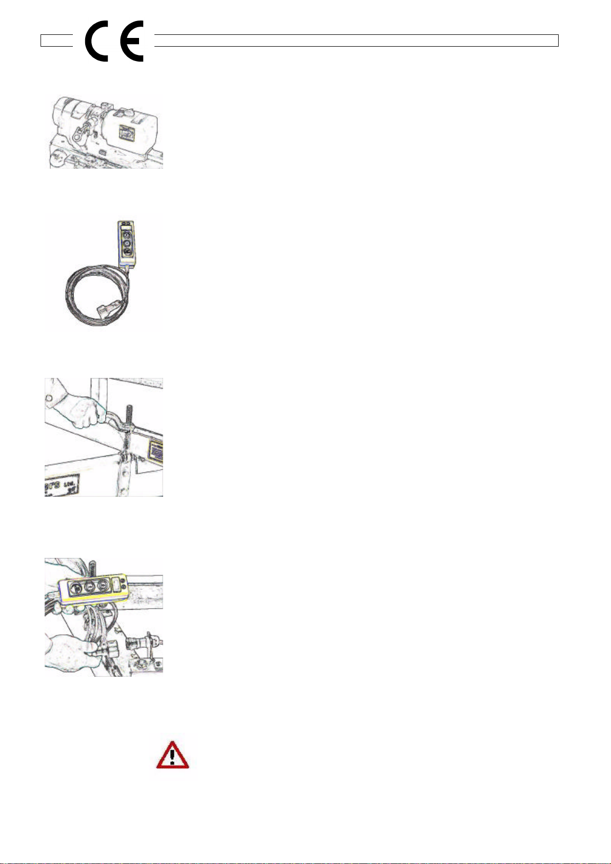
TILTING THE TRAILER BODY
CT166G, CT167G, CT166GA, CT167GA (Fenner Electric Pump)
The tilting system comprises an electro-hydraulic pump (fig 1)
powered by an on-board heavy duty 12V battery to operate a pair
of hydraulic rams. The pump is operated from a remote control
switch pad on a detachable lead (fig 2). An isolator switch with
removable key is also provided to isolate the on-board electrical
system.
Operation
Before commencing tilting operations, the screw/clamps securing
the "A"-frame to the tilting platform should be released (see Fig.3)
Connect the remote control lead to the socket on the side of the
pump. (fig 4) Insert the key into the isolator switch and turn
clockwise through 90o to switch on.
After checking that the rear of the trailer is clear, operate the 'up
arrow' button on the remote control to tilt the trailer platform. To
ensure that the platform cannot be accidentally tilted, disconnect
the remote control lead plug from the socket (a straight pull).
To return the tilting platform to the horizontal position, ensure that
the area between the platform and chassis is clear of obstructions
and operate the 'down arrow' button until the platform is fully
lowered. Turn the isolator key anti-clockwise through 90o to switch
off the system, and remove the key.
During normal operation the 'Green' LED lamp on the remote
control will be lit. If the 'Red' LED lamp lights it will indicate that the
battery charge is low -See pages 6-7 for battery information and
more on control indicators.
ENSURE THAT THE SCREW/CLAMPS ARE IN THE LOCKED
POSITION AND THE ISOLATOR KEY HAS BEEN REMOVED
BEFORE DRIVING AWAY.
Fig.3
Fig.2
Fig.1
Fig.4
Tilt-Bed Trailers 5
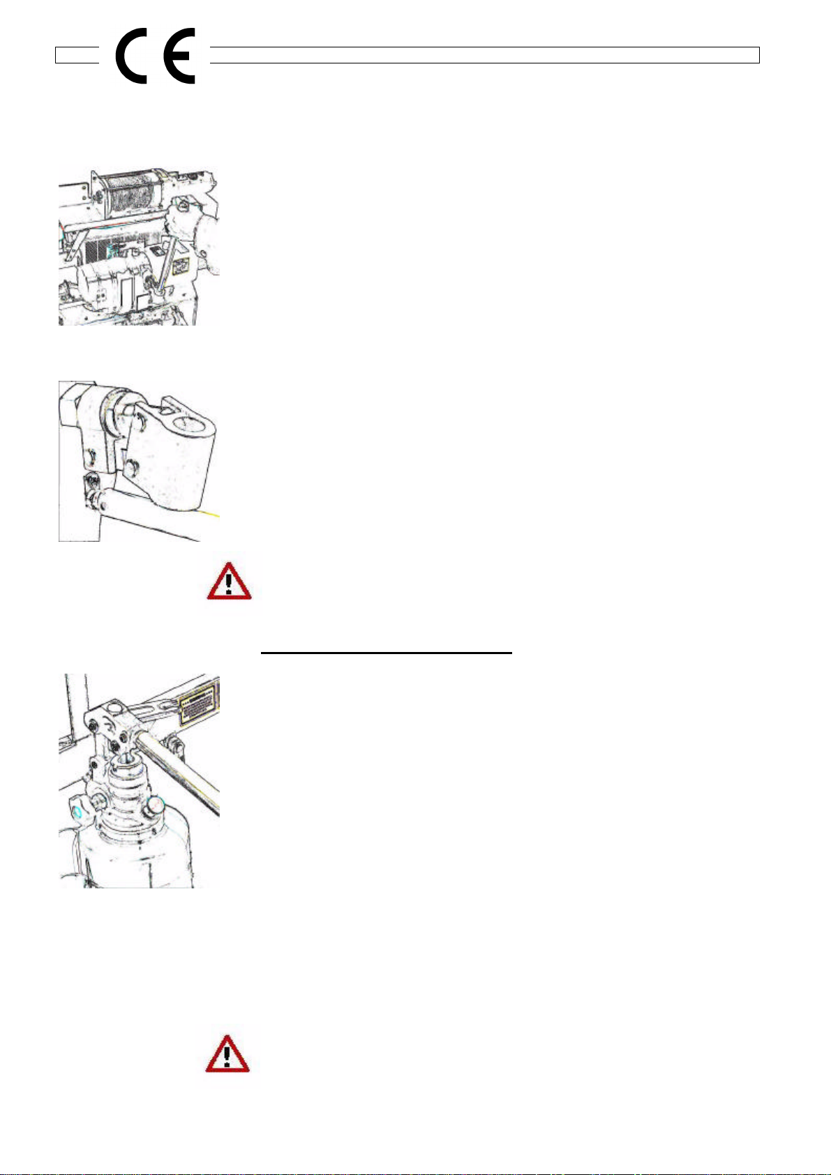
TILTING THE TRAILER BODY (continued)
Manual Operation
back-up system to the electrical pump - (Fig.5)
Operation
Before commencing tilting operations, the screw/clamps securing
the "A"-frame to the tilting platform should be released (see Fig.3)
Ensure that the manual release valve (Fig. 6) is closed by turning
clockwise with the specially shaped end of the pump handle.
Insert the handle into the main socket (as per Fig.5).
After checking that the rear of the trailer is clear, operate the pump
handle to tilt the trailer platform.
To lower the platform, check that the area between the platform and
chassis is clear of obstructions and using the end of the pump
handle open the release valve by slowly turning anti-clockwise.
Control the rate of descent by opening and closing the valve as
required.
When the platform is fully lowered close the release valve so that the
trailer is ready for further use.
ENSURE THAT THE SCREW/CLAMPS ARE IN THE LOCKED
POSITION BEFORE DRIVING AWAY.
Trailers with Manual Pump only
The tilting system comprises a manually operated hydraulic pump to
operate the hydraulic rams (fig 7).
Operation
Before commencing tilting operations, the screw/clamps securing
the "A"-frame to the tilting platform should be released (see Fig.3)
Ensure that the release valve is closed by turning clockwise.
After checking that the rear of the trailer is clear, Operate the hand
lever to tilt the trailer platform.
To lower the platform, check that the area between the platform and
thechassis isclear ofobstructions andslowly openthe releasevalve
by turning anti-clockwise.
Control the rate of descent by opening and closing the valve as
required.
When the platform is fully lowered close the release valve so that the
trailer is ready for further use.
ENSURE THAT THE SCREW/CLAMPS ARE IN THE LOCKED
POSITION BEFORE DRIVING AWAY.
Fig.5
Fig.6
Fig.7
Tilt-Bed Trailers 6
BATTERY
All Models (Electric Pump)
When working on or near the battery, observe the following safety
precautions:
EXPLOSIVE GAS
DO NOT SMOKE. AVOID CONTACT WITH
SPARKS OR FLAMES
CONTAINS SULPHURIC ACID
AVOID SKIN & EYE CONTACT
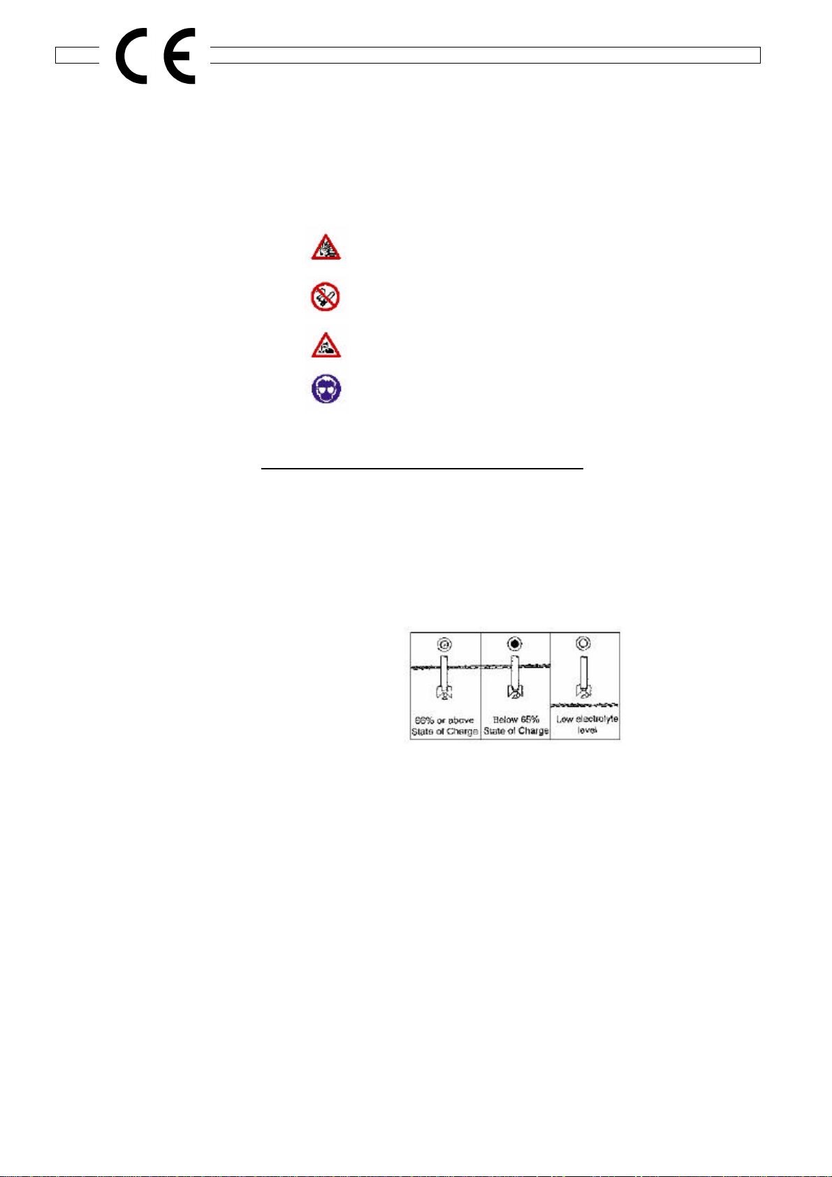
“MAGIC EYE” ‘State of battery’ indicator
(automatic built in hydrometer)
Colour: Green Satisfactory state of charge > 65%
Black Battery requires charging <65%
Yellow I Clear Electrolyte level low *
Green Black Clear
*When the electrolyte level becomes low, do not use the battery
and also check the electrical circuit of the system. The battery must
be replaced via the manufacturer or their agent as shown on the
enclosed manufacturer’s leaflet.
The battery is warranted by the manufacturer against defects in
materials or workmanship for one year - the full details of which are
shown on the leaflet.
BUILT IN HYDROMETER

Tilt-Bed Trailers 7
BATTERY (continued)
BATTERY CHARGING
Battery Charger Selection:
A nominal 12 volt charger rated as follows, is required to maintain
the battery at optimum performance
Battery capacity in Charger size
Ampere hours Rating in Amperes
102Ah (as fitted) 10 to 15A or 20A
The selection of the correct charger rating for your battery size is
important to reduce the risk of premature battery failure:
A charger which is under-sized will not fully recharge the battery.
This will result in a steady reduction of the available battery capacity,
the inability of the battery to complete a normal service cycle, and
eventually irreversible damage leading to battery failure.
A charger that is over-sized can, under certain circumstances, lead
to potential hazardous situations (a: formation of an explosive
gaseous mixture and b: acid spillage - leading to unchargeable dry
cells and exposed acidic fluids), and early battery failure.
Battery Health
Whilst batteries which are not fully charged may still give reasonable
performance, the effect of never allowing the batteries to be
completely recharged will be a gradual reduction in performance and
reduced battery life.

Tilt-Bed Trailers 8
HYDRAULIC SYSTEM MAINTENANCE
1. Wipe all external surfaces of the pump and reservoir tank to
remove dirt, dust and oil residue.
2. Inspect unit for leaks and rectify as necessary.
3. Clean reservoir filler cap, remove and renew if cap and/or seal is
damaged. Check oil level and replenish with clean hydraulic oil.
This should preferably be carried out with actuator (and thus the
body ram) at minimum stroke, i.e. with the trailer body down. The
oil should be approximately 25mm (1”) from the top of the reservoir
tank when full.
4. Fully replace the hydraulic oil at intervals depending upon the
severity of the duty and environment conditions:
Very dirty, dusty and damp: 6months to 1 year
Otherwise, in more favourable conditions: Approx. 2 yearly
Draining the Tank
With the body fully lowered, remove the main pressure supply hose
from the ram (fig 8) and dip into a suitably sized and positioned
container or oil drum. Switch on the electrical operating system (or
operate the manual pump) to pump the oil into the container.
Continue until the oil flow virtually ceases.
DO NOT RUN THE PUMP FOR LONGER THAN IS NECESSARY
WHEN THE TANK IS APPROACHING EMPTY
Filling the Tank
Use clean, filtered oil of the correct grade. Use a filter unit with a
filtration level of 25 microns (25 ?m) or better.
Use only clean jugs and funnels.
CONTAMINATION OF HYDRAULIC OIL ACCOUNTS FOR THE
VAST MAJORITY OF HYDRAULIC SYSTEM FAILURES
Connect the hose to the ram but do not tighten. Fill the tank to the
level mark. Bleed the system by operating the motor briefly whilst
observing the release of air from the hose connection on the ram. As
soon as there is no sign of air escaping, tighten the connector. Check
the oil level and top up if necessary.
Fig.8

Tilt-Bed Trailers 9
HYDRAULIC SYSTEM MAINTENANCE (continued)
HYDRAULIC OIL RECOMMENDATIONS
Mineral oil with a viscosity range from 6 to 450 centistokes at normal working temperature.
The following oils are recommended for use at temperatures between -20oC and +60oC.
Supplier Grade Pour Point Viscosity In Centistokes
0C @00C@40oC
B.P.Trading HLP 32 -33 -- 15
HP 32 -54 -- 15
Burmah Castrol Hyspin VG 15 -39 117 15
Hyspin AWS 15 -39 117 15
Hyspin AWH 15 -51 82 15
Esso Nuto H 15 -35 95 14
Nuto HP 15 -35 95 14
Univis J 13 -59 50 15
ELF Sternol Albatross -40 77 15
Gulf Oil Harmony 15 AW -30 93 14
Lorco HT15 -40 90 14
FVT 15 -40 85 14
Mobile Oil 11 -45 87 17
Shell UK Oil Tellus T 15 -51 75 15
Total Oil GB Azolla 15 N -30 100 15
Equivis VG1S -51 82 15
Where the temperature is constantly below -100C, please consult your oil consultant or supplier.
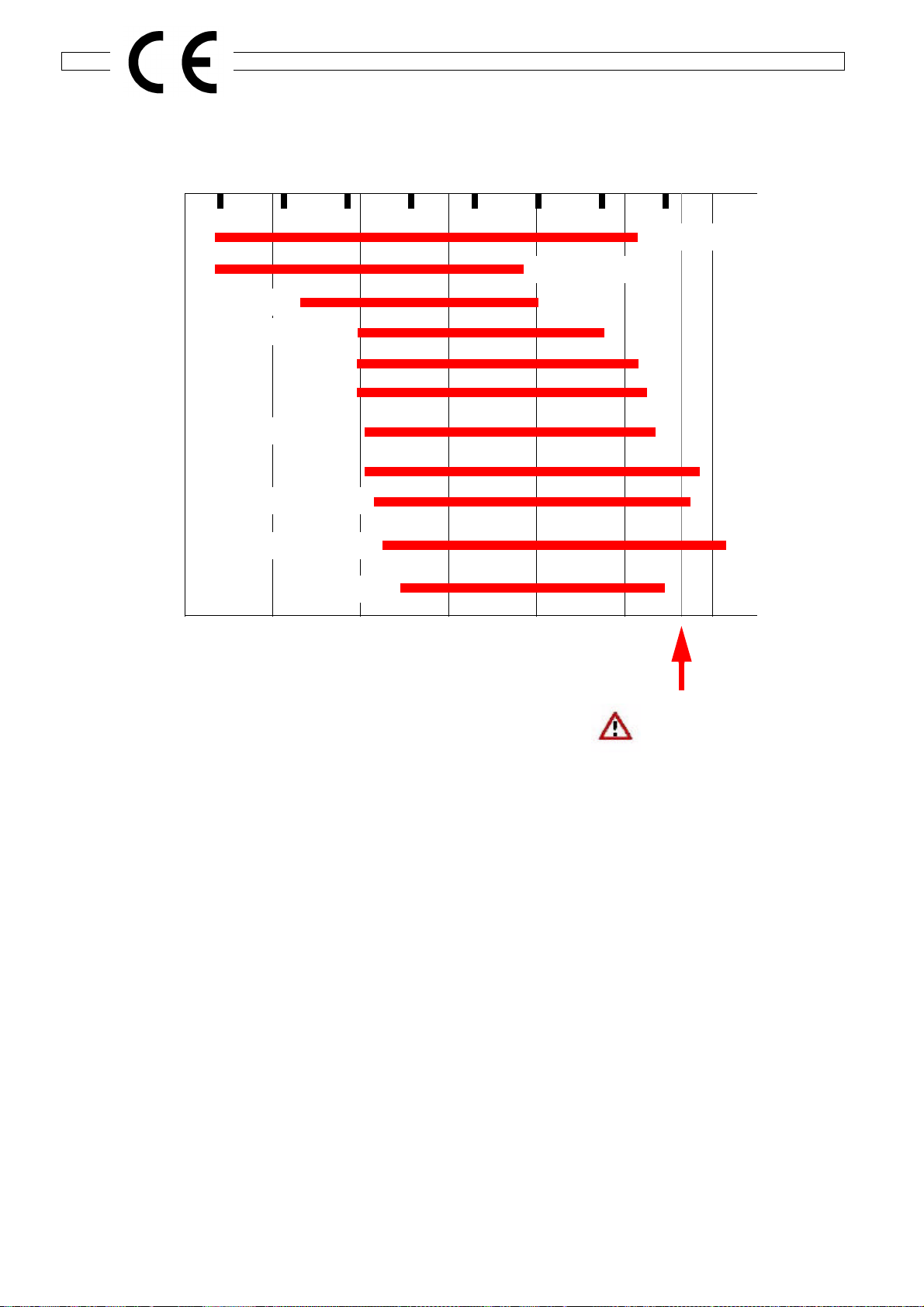
Tilt-Bed Trailers 10
-60 -40 -20 0 20 40 60 80 100
Oil Temperature oC
Oil Temperature oC
-100 -50 0 50 100 150 200
UNIVIS J25
MIL-5506
SAE 15
ISO VG 22
SAE 10
ATF
SAE 5W20
SAE
SAE 10W30
SAE 10W40
SAE 20
MAXIMUM PUMP
OPERATING TEMP
Oil viscosity
Temperature limits based on maximum viscosity of 1000 centistokes (5000 SSU)
and Minimum viscosity of 15 centistokes (80 SSU)

Tilt-Bed Trailers 11
TYRES
Tyres must be maintained at the pressures indicated below. Under-inflation will adversely affect
handling and fuel consumption and will lead to premature wear. If seriously under-inflated, a tyre
will overheat and fail very rapidly.
When renewing tyres, always ensure that you purchase a tyre of the same size and load/speed
index rating. Different makes or models of tyres of the same size can have widely differing load/
speed index ratings and inflation pressures. Using tyres with a lower rating can be dangerous. If
in doubt, ask a tyre distributor or our technical department.
Tyre Fitments
Load/Speed Index Pressure (Cold)
12” Wheels
155/70R12C (tubeless)104/101N 95 psi / 6.5 bar
185/60R12C (tubeless) 104/101N 95 psi / 6.5 bar
13" Wheels
195/50R13C (tubeless) 104/101N 95 psi / 6.5 bar
The maximum gross weight figure given on the trailer plate is always equal to or less than the
approved maximum load for the tyres at 60mph multiplied by the number of tyres on the trailer.
Other maximum load figures are marked on some tyres. These do not apply to the UK or Europe
and should be disregarded
Tyre Repairs
Punctures should be inspected and repaired by a specialist tyre distributor. If the tyre is too
severely damaged for a repair to be carried out the tyre must be replaced.
DO NOT FIT TUBES TO TUBELESS TYRES AS THIS CAN LEAD TO
A "BLOW OUT" IN THE EVENT OF A FURTHER PUNCTURE.

Tilt-Bed Trailers 12
User Notes
Ifor Williams Trailers Ltd., Cynwyd, Corwen, Denbighshire, LL21 OLB, UK - Tel. 01490 412626: Fax 01490 412770
This manual suits for next models
3
Table of contents
Other Ifor Williams Trailers Utility Vehicle manuals


Popular Utility Vehicle manuals by other brands

Taylor-Dunn
Taylor-Dunn C0-014-32 Operation, t roubleshooting and replacement parts manual

Bush Hog
Bush Hog Utility Vehicle Workshop Workshop manual

Kärcher
Kärcher TRS-3500-S Operator's manual

Toro
Toro Groundsmaster 7210 Operator's manual

Toro
Toro 7299 Operator's manual

Ironhorse Trailers
Ironhorse Trailers One bike owner's manual


