IGM Fachmann 125-508819 User manual
man_125-508819_A5br_kolikovaci pripravek_EN+CZ+SK+HU+PL_v.3.2
Operationg instructions
Návod k obsluze
Návod na obshluhu
Használatiútmutató
Instrukcja obsługi
IGM DOWELLING JIG 30MM FOR DOWELS 6, 8 & 10MM
IGM KOLÍKOVACÍ PŘÍPRAVEK 30MM PRO D6, 8 A 10MM
IGM KOLÍKOVACÍ PRÍPRAVOK 30MM PRE D6, 8 A 10MM
IGM MESTERCSAPOZÓ 30MM 6, 8 ÉS 10MMES TIPLIKHEZ
IGM PRZYRZĄD DO DYBLOWANIA 30MM DO D6, 8 I 10MM
125-508819

www.igm.cz
2
Operating instructions / Návod k obsluze /
Návod na obsluhu / Használatiútmutató / Instrukcja obsługi
OPERATING INSTRUCTIONS
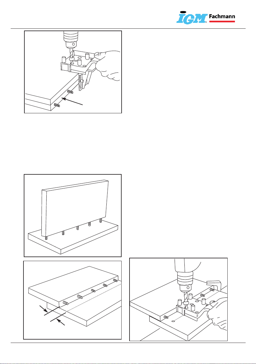
Figure 1 & 2: Mark the positions of the board in relation to
each other (X) and identify the boards with letters A& B.
Figure 3 & 4: Work On Board Afor all dowel joints. Clamp
board Ato the workbench.
Figure 5: Adjusting the drilling depth on board A: Dowel
Lengths (Board thickness of B5mm). For end-grain joints
half the dowel length. Use a drill bit with a depth stop.
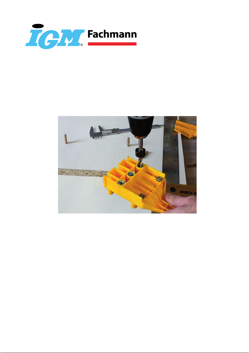
Figure 6, 7 & 8: Drill the holes in board A. Ensure that the
centre pin is pushed firmly against the board by pressing the
handle (see direction of arrow in Figure 8). Also ensure that
the manual dowel locator is placed level on the edge.
Important: First insert the drill bit in the drill bush and then
switch on the power drill.
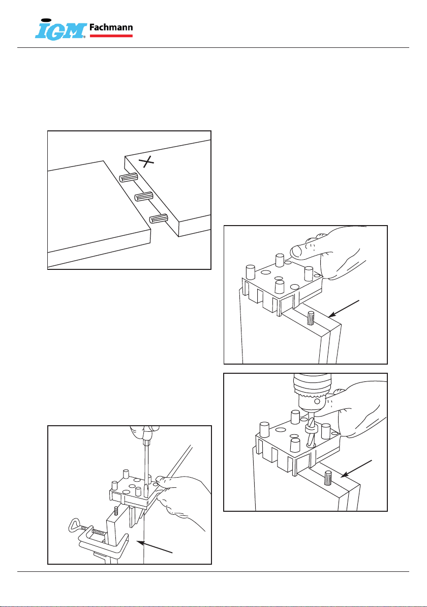
Figure 12: Place the dowel locator on a dowel in board A.
Push the angle fence from the handle side into the guideway
until it rests firmly against the board. Finally tighten the
clamping screw.
6mm
Basic Dowelling Jig Operation
2
A
B
1
4
5
3
6
9
A
10
11
12
7
8
A
B
8mm
10mm
A
10mm
8mm
Max. 30mm
Max. 25mm
Max. 25mm 6mm
A
A
B
508819 Instructions.qxd 5/10/06 2:15 pm Page 2
OPERATING INSTRUCTIONS
Figure 1 & 2: Mark the positions of the board in relation to
each other (X) and identify the boards with letters A& B.
Figure 3 & 4: Work On Board Afor all dowel joints. Clamp
board Ato the workbench.
Figure 5: Adjusting the drilling depth on board A: Dowel
Lengths (Board thickness of B5mm). For end-grain joints
half the dowel length. Use a drill bit with a depth stop.
Figure 6, 7 & 8: Drill the holes in board A. Ensure that the
centre pin is pushed firmly against the board by pressing the
handle (see direction of arrow in Figure 8). Also ensure that
the manual dowel locator is placed level on the edge.
Important: First insert the drill bit in the drill bush and then
switch on the power drill.
Figure 12: Place the dowel locator on a dowel in board A.
Push the angle fence from the handle side into the guideway
until it rests firmly against the board. Finally tighten the
clamping screw.
6mm
Basic Dowelling Jig Operation
2
A
B
1
4
5
36
9
A
10
11
12
7
8
A
B
8mm
10mm
A
10mm
8mm
Max. 30mm
Max. 25mm
Max. 25mm 6mm
A
A
B
508819 Instructions.qxd 5/10/06 2:15 pm Page 2
EN
Figure 1 & 2: Mark the positions of the board in relation to
each other (X) and identify the boards with letters A& B.
CZ
Obrázek 1 a 2: Označuje pozice na desce a označuje desky
písmeny Aa B(obr.1 naznačuje rohový spoj a obr.2 spoj na
tupo.)
SK
Obrázok 1 a 2: Označuje pozície na doske a označuje dosky
písmenami Aa B(obr.1 naznačuje rohový spoj a obr.2 spoj na
tupo.)
HU
1. és 2. ábra: a lapokillesztésének a helyétvalamintaz A ésB
betűvelvalójelölésétábrázolja. (1.ábra – sarokkötés; 2.ábra -
toldás)
PL
Rysunek 1 i 2: Oznacza położenie na płycie oraz znakuje
płyty literami A i B (rys.1 naznacza połączenie kątowe, a rys. 2
połączenie czołowe).
EN
Figure 3 & 4: Work On Board Afor all dowel joints. Clamp
board Ato the workbench.
CZ
Obrázek 3 a 4: Pro vrtání do hrany, upneme desku do svěráku.
(obr.1 ukazuje rohový spoj, obr.2 ukazuje spoj na tupo.)
SK
Obrázok 3 a 4: Na vŕtanie do hrany, upneme dosku do zveráku.
(obr.1 ukazuje rohový spoj, obr.2 ukazuje spoj na tupo.)
HU
3. és 4. ábra:Szegélyfúráshoz a munkalapotfogassukszorítóba.
(1.ábra – sarokkötés, 2. ábra – toldás)
PL
Rysunek 3 i 4: W celu wiercenia do krawędzi należy zamocować
płytę do imadła. (rys.1 pokazuje połączenie kątowe, rys.2
prezentuje połączenie czołowe).

www.igm.cz 3
Operating instructions / Návod k obsluze /
Návod na obsluhu / Használatiútmutató / Instrukcja obsługi
OPERATING INSTRUCTIONS
Figure 1 & 2: Mark the positions of the board in relation to
each other (X) and identify the boards with letters A& B.
Figure 3 & 4: Work On Board Afor all dowel joints. Clamp
board Ato the workbench.
Figure 5: Adjusting the drilling depth on board A: Dowel
Lengths (Board thickness of B5mm). For end-grain joints
half the dowel length. Use a drill bit with a depth stop.
Figure 6, 7 & 8: Drill the holes in board A. Ensure that the
centre pin is pushed firmly against the board by pressing the
handle (see direction of arrow in Figure 8). Also ensure that
the manual dowel locator is placed level on the edge.
Important: First insert the drill bit in the drill bush and then
switch on the power drill.
Figure 12: Place the dowel locator on a dowel in board A.
Push the angle fence from the handle side into the guideway
until it rests firmly against the board. Finally tighten the
clamping screw.
6mm
Basic Dowelling Jig Operation
2
A
B
1
4
5
36
9
A
10
11
12
7
8
A
B
8mm
10mm
A
10mm
8mm
Max. 30mm
Max. 25mm
Max. 25mm 6mm
A
A
B
508819 Instructions.qxd 5/10/06 2:15 pm Page 2
OPERATING INSTRUCTIONS
Figure 1 & 2: Mark the positions of the board in relation to
each other (X) and identify the boards with letters A& B.
Figure 3 & 4: Work On Board Afor all dowel joints. Clamp
board Ato the workbench.
Figure 5: Adjusting the drilling depth on board A: Dowel
Lengths (Board thickness of B5mm). For end-grain joints
half the dowel length. Use a drill bit with a depth stop.
Figure 6, 7 & 8: Drill the holes in board A. Ensure that the
centre pin is pushed firmly against the board by pressing the
handle (see direction of arrow in Figure 8). Also ensure that
the manual dowel locator is placed level on the edge.
Important: First insert the drill bit in the drill bush and then
switch on the power drill.
Figure 12: Place the dowel locator on a dowel in board A.
Push the angle fence from the handle side into the guideway
until it rests firmly against the board. Finally tighten the
clamping screw.
6mm
Basic Dowelling Jig Operation
2
A
B
1
4
5
3
6
9
A
10
11
12
7
8
A
B
8mm
10mm
A
10mm
8mm
Max. 30mm
Max. 25mm
Max. 25mm 6mm
A
A
B
508819 Instructions.qxd 5/10/06 2:15 pm Page 2
EN
Figure 5: Adjusting the drilling depth on board A: Dowel
Lengths (Board thickness of B5mm). For end-grain joints
half the dowel length. Use a drill bit with a depth stop.
CZ
Obrázek 5: Nastavení hloubky vrtání do hrany: Prostrčte vrták
vrtacím pouzdrem nastavte délku poloviny délky kolíku +5mm.
Použijte vrták s hloubkovým dorazem.
SK
Obrázok 5: Nastavenie hĺbky vŕtania do hrany: Prestrčte vrták
vŕtacím puzdrom nastavte dĺžku polovice dĺžky kolíka +5 mm.
Použite vrták s hĺbkovým dorazom.
HU
5. ábra: A mélységbeállításaszegélyfúráshoz:Helyezze a fúrót
a fúróhüvelyenkeresztülúgy, hogy a fúrócsapozóalattihossza
megfeleljen a tiplihosszafelénekéshagyjonrá +5mm-t.
Használjonmélyütközöt a fúrófejen.
PL
Rysunek 5: Nastawienie głębokości wiercenia do krawędzi:
Przeciągnij wiertło uchwytem wiertarskim. Następnie ustaw
długość połowy długości kołka + 5 mm. Zastosuj wiertło z
ogranicznikiem głębokości.
EN
Figure 6, 7 & 8: Drill the holes in board A. Ensure that the
centre pin is pushed rmly against the board by pressing the
handle (see direction of arrow in Figure 8). Also ensure that
the manual dowel locator is placed level on the edge.
Important: First insert the drill bit in the drill bush and then
switch on the power drill.
OPERATING INSTRUCTIONS
Figure 1 & 2: Mark the positions of the board in relation to
each other (X) and identify the boards with letters A& B.
Figure 3 & 4: Work On Board Afor all dowel joints. Clamp
board Ato the workbench.
Figure 5: Adjusting the drilling depth on board A: Dowel
Lengths (Board thickness of B5mm). For end-grain joints
half the dowel length. Use a drill bit with a depth stop.
Figure 6, 7 & 8: Drill the holes in board A. Ensure that the
centre pin is pushed firmly against the board by pressing the
handle (see direction of arrow in Figure 8). Also ensure that
the manual dowel locator is placed level on the edge.
Important: First insert the drill bit in the drill bush and then
switch on the power drill.
Figure 12: Place the dowel locator on a dowel in board A.
Push the angle fence from the handle side into the guideway
until it rests firmly against the board. Finally tighten the
clamping screw.
6mm
Basic Dowelling Jig Operation
2
A
B
1
4
5
36
9
A
10
11
12
7
8
A
B
8mm
10mm
A
10mm
8mm
Max. 30mm
Max. 25mm
Max. 25mm 6mm
A
A
B
508819 Instructions.qxd 5/10/06 2:15 pm Page 2
CZ
Obrázek 6, 7 a 8: Vyvrtejte otvory do hrany desky A. Ujistěte se,
že středový čep je pevně přitlačen k desce. Tiskněte rukojeť viz
směr šipky na obr. 8.
Důležité:Nejprve vložte vrták do vrtacího pouzdra a pak
zapněte vrtačku.
SK
Obrázok 6, 7 a 8: Vyvŕtajte otvory do hrany dosky A. Uistite sa,
že stredový čap je pevne pritlačený k doske. Tlačte rukoväť pozri
smer šípky na obr 8.
Dôležité: Najprv vložte vrták do vŕtacieho puzdra a potom
zapnite vŕtačku.
HU
6. 7. és 8. ábra: FúrjakiazA munkalapnyílásait. Ügyeljenarra,
hogy a központicsapkellőennyomódjon a munkalaphoz.
A fogantyútnyomja a 8. ábra alapjánszemléltetettnyilak
irányába.
Figyelem: Előbbhelyezze a fúrót a fúróhüvelybe, csakazután
kapcsoljabe a fúrógépet.
PL
Rysunek 6, 7 i 8: Wywierć otwory w krawędzi płyty A. Upewnij
się, że centralny czop jest mocno dociśnięty do płyty. Naciśnij
rękojeść zgodnie z kierunkiem strzałki na rys. 8. Ważne: Najpierw
wsuń wiertło do uchwytu wiertarskiego, a następnie włącz
wiertarkę.

www.igm.cz
4
Operating instructions / Návod k obsluze /
Návod na obsluhu / Használatiútmutató / Instrukcja obsługi
EN
Figure 13 & 14: Place board Bin a desired position on
board Aand clamp to the workbench.
Important: The depth stop must be re-adjusted (board
thickness 5mm). Place the dowel locator over the
corresponding dowel of board Ain such a manner that the
angle fence rests rmly against the board and drill.
CZ
Obrázek 13 & 14: Položte desku Bna desku Aviz obr.13
(zarovnejte hrany). Upněte desky k pracovnímu stolu
Důležité: Hloubka dorazu se musí znovu upravit. Prostrčte vrták
vrtacím pouzdrem a nastavte délku jako je tloušťka desky B
-5mm.
Umístěte postraní doraz na kolík (příslušným otvorem
postraního dorazu podle použitého vrtacího pouzdra) Přitlačte k
desce a vrtejte do plochy.
SK
Obrázok 13 & 14: Položte dosku Bna dosku Apozri obr.13
(zarovnajte hrany). Upnite dosky k pracovnému stolu
Dôležité: Hĺbka dorazu sa musí znovu upraviť. Prestrčte vrták
vŕtacím pouzdrom a nastavte dĺžku ako je hrúbka dosky B-5mm.
Umiestnite postrannej doraz na kolík (príslušným otvorom
postraního dorazu podľa použitého vŕtacieho puzdra) Pritlačte k
doske a vŕtajte do plochy.
OPERATING INSTRUCTIONS
Figure 1 & 2: Mark the positions of the board in relation to
each other (X) and identify the boards with letters A& B.
Figure 3 & 4: Work On Board Afor all dowel joints. Clamp
board Ato the workbench.
Figure 5: Adjusting the drilling depth on board A: Dowel
Lengths (Board thickness of B5mm). For end-grain joints
half the dowel length. Use a drill bit with a depth stop.
Figure 6, 7 & 8: Drill the holes in board A. Ensure that the
centre pin is pushed firmly against the board by pressing the
handle (see direction of arrow in Figure 8). Also ensure that
the manual dowel locator is placed level on the edge.
Important: First insert the drill bit in the drill bush and then
switch on the power drill.
Figure 12: Place the dowel locator on a dowel in board A.
Push the angle fence from the handle side into the guideway
until it rests firmly against the board. Finally tighten the
clamping screw.
6mm
Basic Dowelling Jig Operation
2
A
B
1
4
5
36
9
A
10
11
12
7
8
A
B
8mm
10mm
A
10mm
8mm
Max. 30mm
Max. 25mm
Max. 25mm 6mm
A
A
B
508819 Instructions.qxd 5/10/06 2:15 pm Page 2
EN
Figure 12: Place the dowel locator on a dowel in board A.
Push the angle fence from the handle side into the guideway
until it rests rmly against the board. Finally tighten the
clamping screw.
CZ
Obrázek 12: Umístěte hmoždinku do desky Aa položte na ní
vrtací čep, přitlačte postraní doraz a dotáhněte šrouby.
SK
Obrázok 12: Umiestnite hmoždinku do dosky Aa položte na nej
vŕtacie čap, pritlačte postranný doraz a dotiahnite skrutky.
HU
12. ábra: Helyezze a rögzítőtiplitazA munkalapraés
tegyerá a mestercsapozót.Szereljefelazoldalütköztetőt,
majdhúzzabe a szorítócsavart.
PL
Rysunek 12: Umieść kołek w płycie A potem nałóż na niego
czop wiertarski, dociśnij boczny ogranicznik, a następnie dokręć
śruby.
OPERATING INSTRUCTIONS
Figure 1 & 2: Mark the positions of the board in relation to
each other (X) and identify the boards with letters A& B.
Figure 3 & 4: Work On Board Afor all dowel joints. Clamp
board Ato the workbench.
Figure 5: Adjusting the drilling depth on board A: Dowel
Lengths (Board thickness of B5mm). For end-grain joints
half the dowel length. Use a drill bit with a depth stop.
Figure 6, 7 & 8: Drill the holes in board A. Ensure that the
centre pin is pushed firmly against the board by pressing the
handle (see direction of arrow in Figure 8). Also ensure that
the manual dowel locator is placed level on the edge.
Important: First insert the drill bit in the drill bush and then
switch on the power drill.
Figure 12: Place the dowel locator on a dowel in board A.
Push the angle fence from the handle side into the guideway
until it rests firmly against the board. Finally tighten the
clamping screw.
6mm
Basic Dowelling Jig Operation
2
A
B
1
4
5
36
9
A
10
11
12
7
8
A
B
8mm
10mm
A
10mm
8mm
Max. 30mm
Max. 25mm
Max. 25mm 6mm
A
A
B
508819 Instructions.qxd 5/10/06 2:15 pm Page 2

www.igm.cz 5
Operating instructions / Návod k obsluze /
Návod na obsluhu / Használatiútmutató / Instrukcja obsługi
Figure 16 & 17: Place the board B in the desired position on
board Aand clamp firmly. Draw a centre line for the dowel
holes on board B. Place the dowel locator with the side
centre marks on the centre line, push the angle fence
against board B and clamp. Then drill as shown in Figure
14.
Figure 18: T-Joint.
Figure 19 & 20: Draw a centre line for the dowel holes on
board B. Clamp board Aat a distance of 35mm from the
drawn line.
Important: The depth stop must be re-adjusted (board
thickness 5mm). Now place the dowel locator with the
corresponding guiding groove over the dowel. When drilling
ensure that the centre marks are aligned with the centre line.
Figure 21: End-grain joints.
Figure 22: Place the dowel locator on a dowel in board A.
Then push the angle fence from the handle side into the
guideway until it rests firmly against the board. Finally tighten
the clamping screw.
Figure 23 & 24: Clamp board A& Bin such a manner that
the marks are visible. Push the dowel locator with the
corresponding guiding groove over the dowel until the angle
fence rests firmly against the board and then drill.
Figure 13 & 14: Place board B in a desired position on
board Aand clamp to the workbench.
Important: The depth stop must be re-adjusted (board
thickness 5mm). Place the dowel locator over the
corresponding dowel of board Ain such a manner that the
angle fence rests firmly against the board and drill.
Figure 15: The distance of the dowel from the edge is
maximum 25mm.
13
A
B
A
A
B
B
14
25mm
35mm
16
17
18
15
B
19
22
23
24
20
21
A
B
A
B
A
B
A
B
A
A
A
B
A
508819 Instructions.qxd 5/10/06 2:15 pm Page 3
EN
Figure 15:The distance of the dowel from the edge is
maximum 25mm.
CZ
Obrázek 15: Vzdálenost hmoždinek od okraje je maximální
25mm.
EN
Figure 16 & 17: Place the board Bin the desired position on
board Aand clamp rmly. Draw a centre line for the dowel
holes on board B. Place the dowel locator with the side
centre marks on the centre line, push the angle fence
against board Band clamp.Then drill as shown in Figure 14
.
CZ
Obrázek 16 a 17: Pro rohový spoj, který má být odsazený od
hrany nakreslete středovou osu kolíků na desku B. Povolte
postraní doraz. Položte kolíkovací přípravek na desku Ba opřete
doraz o hranu viz obr.17 srovnejte osy děr podle naznačené osy
obr.16 a dotáhněte šrouby dorazu.
SK
Obrázok 16 a 17: Pre rohový spoj, ktorý má byť odsadený
od hrany nakreslite stredovú osu kolíkov na dosku B. Povoľte
postrannej doraz. Položte kolíkovací prípravok na dosku Ba
oprite doraz o hranu pozri obr.17 porovnajte osi dier podľa
naznačenej osi obr.16 a dotiahnite skrutky dorazu.
HU
16. és 17. ábra: Sarokkötéshezrajzoljafel a tiplikelcsúsztatott
tengelyét a Bmunkalapra. Lazítsafelazoldalütköztetőt.
Helyezze a gyorstiplizőt a B munkalapraéstámasszahozzáaz
oldalütköztetőtlásd17.ábra, a hüvelyektengelyéthelyezze
a felrajzolttengelyrelásd16.ábra, majdhúzzabe a csavarokat.
PL
Rysunki 16 i 17: Aby połączenie kątowe było umieszczone dalej
od krawędzi narysuj na płycie B oś centralną. Poluzuj boczny
ogranicznik. Na płytę Bumieść przyrząd do dyblowania oraz
oprzyj ogranicznik o krawędź, patrz rys.17.Następnie wyrównaj
osie otworów zgodnie z oznaczoną osią rys.16.Teraz dokręć
śruby oporowe
Figure 16 & 17: Place the board B in the desired position on
board Aand clamp firmly. Draw a centre line for the dowel
holes on board B. Place the dowel locator with the side
centre marks on the centre line, push the angle fence
against board B and clamp. Then drill as shown in Figure
14.
Figure 18: T-Joint.
Figure 19 & 20: Draw a centre line for the dowel holes on
board B. Clamp board Aat a distance of 35mm from the
drawn line.
Important: The depth stop must be re-adjusted (board
thickness 5mm). Now place the dowel locator with the
corresponding guiding groove over the dowel. When drilling
ensure that the centre marks are aligned with the centre line.
Figure 21: End-grain joints.
Figure 22: Place the dowel locator on a dowel in board A.
Then push the angle fence from the handle side into the
guideway until it rests firmly against the board. Finally tighten
the clamping screw.
Figure 23 & 24: Clamp board A& Bin such a manner that
the marks are visible. Push the dowel locator with the
corresponding guiding groove over the dowel until the angle
fence rests firmly against the board and then drill.
Figure 13 & 14: Place board B in a desired position on
board Aand clamp to the workbench.
Important: The depth stop must be re-adjusted (board
thickness 5mm). Place the dowel locator over the
corresponding dowel of board Ain such a manner that the
angle fence rests firmly against the board and drill.
Figure 15: The distance of the dowel from the edge is
maximum 25mm.
13
A
B
A
A
B
B
14
25mm
35mm
16
17
18
15
B
19
22
23
24
20
21
A
B
A
B
A
B
A
B
A
A
A
B
A
508819 Instructions.qxd 5/10/06 2:15 pm Page 3
HU
13. és 14. ábra: Helyezze a Blapotaz A lapra, lásd13.ábra
(rendezzeegymásfölé a munkalapokszélét). Rögzítse
a munkalapokat a munkaasztalhoz.
Figyelem: A mélyütközőtújrabekellállítani. Nyomjaát
a fúrót a fúróhüvelyenkeresztülés a fúróhosszátállítsa a B
munkalapvastagságától 5mm-rel kevesebbre.
Helyezzeráazoldalütköztetőt a tiplire (azoldalütköztető
megfelelőnyílását a fúróhüvelyhasználataszerint).
A csapozótnyomja a munkalaphoz, majdfúrjon a felületbe.
PL
Rysunek 13 i 14: Umieść płytę B na płycie A tak jak jest
pokazane na rys.13 (wyrównaj krawędzie). Przymocuj płyty do
blatu stołu roboczego.
Ważne: Głębokość ogranicznika musi zostać ponownie
ustawiona.Przeciągnij wiertło przez uchwyt wiertarski i ustaw
długość,która ma być taka sama jak grubość płyty B -5mm.
Umieść boczny ogranicznik na kołek (odpowiednim otworem
bocznego ogranicznika według zastosowanego uchwytu
wiertarskiego).Dociśnij mocno do płyty i wierć do powierzchni.
SK
Obrázok 15: Vzdialenosť hmoždiniek od okraja je
maximálna 25mm.
HU
15. ábra:A fatipliktávolsága a munkalapszélétől
maximum 25mm-relehetnek.
PL
Rysunek 15: Odległość kołków od krawędzi powinna
wynosić maks. 25 mm.
www.igm.cz
6
Operating instructions / Návod k obsluze /
Návod na obsluhu / Használatiútmutató / Instrukcja obsługi
Figure 16 & 17: Place the board B in the desired position on
board Aand clamp firmly. Draw a centre line for the dowel
holes on board B. Place the dowel locator with the side
centre marks on the centre line, push the angle fence
against board B and clamp. Then drill as shown in Figure
14.
Figure 18: T-Joint.
Figure 19 & 20: Draw a centre line for the dowel holes on
board B. Clamp board Aat a distance of 35mm from the
drawn line.
Important: The depth stop must be re-adjusted (board
thickness 5mm). Now place the dowel locator with the
corresponding guiding groove over the dowel. When drilling
ensure that the centre marks are aligned with the centre line.
Figure 21: End-grain joints.
Figure 22: Place the dowel locator on a dowel in board A.
Then push the angle fence from the handle side into the
guideway until it rests firmly against the board. Finally tighten
the clamping screw.
Figure 23 & 24: Clamp board A& Bin such a manner that
the marks are visible. Push the dowel locator with the
corresponding guiding groove over the dowel until the angle
fence rests firmly against the board and then drill.
Figure 13 & 14: Place board B in a desired position on
board Aand clamp to the workbench.
Important: The depth stop must be re-adjusted (board
thickness 5mm). Place the dowel locator over the
corresponding dowel of board Ain such a manner that the
angle fence rests firmly against the board and drill.
Figure 15: The distance of the dowel from the edge is
maximum 25mm.
13
A
B
A
A
B
B
14
25mm
35mm
16
17
18
15
B
19
22
23
24
20
21
A
B
A
B
A
B
A
B
A
A
A
B
A
508819 Instructions.qxd 5/10/06 2:15 pm Page 3
EN
Figure 19 & 20: Draw a centre line for the dowel holes on
board B. Clamp board Aat a distance of 35mm from the
drawn line.
Important: The depth stop must be re-adjusted (board
thickness 5mm). Now place the dowel locator with the
corresponding guiding groove over the dowel. When drilling
ensure that the centre marks are aligned with the centre line.
CZ
Obrázek 19 a 20: Nakreslete středovou čáru pro otvory pro
kolíky na desce B. Položte desku Ave vzdálenosti 35mm od
nakreslené čáry.
Důležité: Hloubka dorazu se musí znovu upravit. Prostrčte vrták
vrtacím pouzdrem a nastavte délku jako je tloušťka desky B
-5mm.
Odmontujte postraní doraz. Položte kolíkovací přípravek na
desku B viz obr.20 před vrtáním se ujistěte, že středová čára
prochází přes středy vrtacích pouzder.
SK
Obrázok 19 a 20: Nakreslite stredovú čiaru pre otvory pre
kolíky na doske B. Položte dosku Avo vzdialenosti 35 mm od
nakreslené čiary.
Dôležité: Hĺbka dorazu sa musí znovu upraviť. Prestrčte vrták
vŕtacím puzdrom a nastavte dĺžku ako je hrúbka dosky B-5mm.
Odmontujte postrannej doraz. Položte kolíkovací prípravok na
dosku Bpozri obr.20 pred vŕtaním sa uistite, že stredová čiara
prechádza cez stredy vŕtacích puzdier.
HU
19. és 20. ábra: A Bmunkalaprarajzoljafel a fatiplik
nyílásainakközépvonalát.TegyeazA táblát 35mm távolságra
a felrajzoltvonaltól.
Figyelem:A mélyütközőtújrabekellállítani. Nyomjaát a fúrót
a fúróhüvelyenkeresztülés a fúróhosszátállítsa a Btábla
vastagságától 5mm-rel kevesebbre.
Távolítsaelazoldalütköztetőt. A gyorstiplizőthelyezze a B
munkalapralásd20.ábra, majd a fúráselőttgyőződjönmeg
arról, hogy a középvonalkeresztülhaladjon a fúróhüvelyek
közepén.
PL
Rysunek 19 i 20:Na płycie B narysuj linię centralną dla otworów
pod kołki. Płytę A umieść w odległości 35 mm od narysowanej
linii.
Ważne:Głębokość ogranicznika musi zostać ponownie
ustawiona.Przeciągnij wiertło przez uchwyt wiertarski i ustaw
długość,która ma być taka sama jak grubość płyty B -5mm.
Usuń boczny ogranicznik. Na płytę B umieść przyrząd do
dyblowania, patrz rys. 20. Przed rozpoczęciem wiercenia,
upewnij się, że linia centralna przechodzi przez środek
uchwytów wiertarskich.
Figure 16 & 17: Place the board B in the desired position on
board Aand clamp firmly. Draw a centre line for the dowel
holes on board B. Place the dowel locator with the side
centre marks on the centre line, push the angle fence
against board B and clamp. Then drill as shown in Figure
14.
Figure 18: T-Joint.
Figure 19 & 20: Draw a centre line for the dowel holes on
board B. Clamp board Aat a distance of 35mm from the
drawn line.
Important: The depth stop must be re-adjusted (board
thickness 5mm). Now place the dowel locator with the
corresponding guiding groove over the dowel. When drilling
ensure that the centre marks are aligned with the centre line.
Figure 21: End-grain joints.
Figure 22: Place the dowel locator on a dowel in board A.
Then push the angle fence from the handle side into the
guideway until it rests firmly against the board. Finally tighten
the clamping screw.
Figure 23 & 24: Clamp board A& Bin such a manner that
the marks are visible. Push the dowel locator with the
corresponding guiding groove over the dowel until the angle
fence rests firmly against the board and then drill.
Figure 13 & 14: Place board B in a desired position on
board Aand clamp to the workbench.
Important: The depth stop must be re-adjusted (board
thickness 5mm). Place the dowel locator over the
corresponding dowel of board Ain such a manner that the
angle fence rests firmly against the board and drill.
Figure 15: The distance of the dowel from the edge is
maximum 25mm.
13
A
B
A
A
B
B
14
25mm
35mm
16
17
18
15
B
19
22
23
24
20
21
A
B
A
B
A
B
A
B
A
A
A
B
A
508819 Instructions.qxd 5/10/06 2:15 pm Page 3
EN
Figure 18: T-Joint.
CZ
Obrázek 18: T-spoj.
SK
Obrázok 18: T-spoj.
HU
18. ábra: T-kötés.
PL
Rysunek 18: T-połączenie.
Figure 16 & 17: Place the board B in the desired position on
board Aand clamp firmly. Draw a centre line for the dowel
holes on board B. Place the dowel locator with the side
centre marks on the centre line, push the angle fence
against board B and clamp. Then drill as shown in Figure
14.
Figure 18: T-Joint.
Figure 19 & 20: Draw a centre line for the dowel holes on
board B. Clamp board Aat a distance of 35mm from the
drawn line.
Important: The depth stop must be re-adjusted (board
thickness 5mm). Now place the dowel locator with the
corresponding guiding groove over the dowel. When drilling
ensure that the centre marks are aligned with the centre line.
Figure 21: End-grain joints.
Figure 22: Place the dowel locator on a dowel in board A.
Then push the angle fence from the handle side into the
guideway until it rests firmly against the board. Finally tighten
the clamping screw.
Figure 23 & 24: Clamp board A& Bin such a manner that
the marks are visible. Push the dowel locator with the
corresponding guiding groove over the dowel until the angle
fence rests firmly against the board and then drill.
Figure 13 & 14: Place board B in a desired position on
board Aand clamp to the workbench.
Important: The depth stop must be re-adjusted (board
thickness 5mm). Place the dowel locator over the
corresponding dowel of board Ain such a manner that the
angle fence rests firmly against the board and drill.
Figure 15: The distance of the dowel from the edge is
maximum 25mm.
13
A
B
A
A
B
B
14
25mm
35mm
16
17
18
15
B
19
22
23
24
20
21
A
B
A
B
A
B
A
B
A
A
A
B
A
508819 Instructions.qxd 5/10/06 2:15 pm Page 3
www.igm.cz 7
Operating instructions / Návod k obsluze /
Návod na obsluhu / Használatiútmutató / Instrukcja obsługi
Figure 16 & 17: Place the board B in the desired position on
board Aand clamp firmly. Draw a centre line for the dowel
holes on board B. Place the dowel locator with the side
centre marks on the centre line, push the angle fence
against board B and clamp. Then drill as shown in Figure
14.
Figure 18: T-Joint.
Figure 19 & 20: Draw a centre line for the dowel holes on
board B. Clamp board Aat a distance of 35mm from the
drawn line.
Important: The depth stop must be re-adjusted (board
thickness 5mm). Now place the dowel locator with the
corresponding guiding groove over the dowel. When drilling
ensure that the centre marks are aligned with the centre line.
Figure 21: End-grain joints.
Figure 22: Place the dowel locator on a dowel in board A.
Then push the angle fence from the handle side into the
guideway until it rests firmly against the board. Finally tighten
the clamping screw.
Figure 23 & 24: Clamp board A& Bin such a manner that
the marks are visible. Push the dowel locator with the
corresponding guiding groove over the dowel until the angle
fence rests firmly against the board and then drill.
Figure 13 & 14: Place board B in a desired position on
board Aand clamp to the workbench.
Important: The depth stop must be re-adjusted (board
thickness 5mm). Place the dowel locator over the
corresponding dowel of board Ain such a manner that the
angle fence rests firmly against the board and drill.
Figure 15: The distance of the dowel from the edge is
maximum 25mm.
13
A
B
A
A
B
B
14
25mm
35mm
16
17
18
15
B
19
22
23
24
20
21
A
B
A
B
A
B
A
B
A
A
A
B
A
508819 Instructions.qxd 5/10/06 2:15 pm Page 3
EN
Figure 22: Place the dowel locator on a dowel in board A.
Then push the angle fence from the handle side into the
guideway until it rests rmly against the board. Finally tighten
the clamping screw.
CZ
Obrázek 22: Umístěte hmoždinku do desky Aa položte na
ní vrtací čep, přitlačte postraní doraz a dotáhněte šrouby. viz
obr.22
SK
Obrázok 22: Umiestnite hmoždinku do dosky Aa položte na
ňu vŕtacii čap, pritlačte postranný doraz a dotiahnite skrutky.
pozri Obr.22
HU
22. ábra: Helyezze a fatipliketazA munkalapnyílasaiba, majd
tegyerá a mestercsapozót, helyezzefelazoldalütköztetőtés
húzzabe a szorítócsavarokat. Lásd 22.ábra
PL
Rysunek 22: W płycie Aumieść kołek, następnie nałóż na niego czop
wiertarski, dociśnij boczny ogranicznik i dokręć śruby, patrz rys. 22.
Figure 16 & 17: Place the board B in the desired position on
board Aand clamp firmly. Draw a centre line for the dowel
holes on board B. Place the dowel locator with the side
centre marks on the centre line, push the angle fence
against board B and clamp. Then drill as shown in Figure
14.
Figure 18: T-Joint.
Figure 19 & 20: Draw a centre line for the dowel holes on
board B. Clamp board Aat a distance of 35mm from the
drawn line.
Important: The depth stop must be re-adjusted (board
thickness 5mm). Now place the dowel locator with the
corresponding guiding groove over the dowel. When drilling
ensure that the centre marks are aligned with the centre line.
Figure 21: End-grain joints.
Figure 22: Place the dowel locator on a dowel in board A.
Then push the angle fence from the handle side into the
guideway until it rests firmly against the board. Finally tighten
the clamping screw.
Figure 23 & 24: Clamp board A& Bin such a manner that
the marks are visible. Push the dowel locator with the
corresponding guiding groove over the dowel until the angle
fence rests firmly against the board and then drill.
Figure 13 & 14: Place board B in a desired position on
board Aand clamp to the workbench.
Important: The depth stop must be re-adjusted (board
thickness 5mm). Place the dowel locator over the
corresponding dowel of board Ain such a manner that the
angle fence rests firmly against the board and drill.
Figure 15: The distance of the dowel from the edge is
maximum 25mm.
13
A
B
A
A
B
B
14
25mm
35mm
16
17
18
15
B
19
22
23
24
20
21
A
B
A
B
A
B
A
B
A
A
A
B
A
508819 Instructions.qxd 5/10/06 2:15 pm Page 3
EN
Figure 21: End-grain joints.
CZ
Obrázek 21: Spoj na tupo
SK
Obrázok 21: Spoj na tupo
HU
21. ábra: Toldás.
PL
Rysunek 21: Połączenie czołowe
EN
Figure 23 & 24: Clamp board A& Bin such a manner that
the marks are visible. Push the dowel locator with the
corresponding guiding groove over the dowel until the angle
fence rests rmly against the board and then drill.
CZ
Obrázek 23 & 24: Přiložte desku Bk desce Aa navlečte otvor
před vrtacím pouzdrem na kolík (vizobr.23). Doražte postraní
doraz. Vyvrtejte otvor do desky B.
SK
Obrázok 23 & 24: Priložte dosku Bk doske Apozri a navlečte
otvor pred vŕtacím puzdrom na kolík (pozri obr.23). Dorazte
postrannej doraz. Vyvŕtajte otvor do dosky B.
HU
23. és 24. ábra: A BmunkalapothelyezzeazA táblamellé,
ésültesse a csapozót a fúrnikívántlyukfelettifatiplire (lásd
23. kép). Ültessefelazoldalütköztetőt. Fúrjaki a B tábla
nyílását.
PL
Rysunek 23 i 24: Przyłóż płytę B do płyty A i nawlecz otwór
przed uchwytem wiertarskim na kołek (patrz rys. 23). Wbij
boczny ogranicznik. Wywierć otwór w płycie B.
Figure 16 & 17: Place the board B in the desired position on
board Aand clamp firmly. Draw a centre line for the dowel
holes on board B. Place the dowel locator with the side
centre marks on the centre line, push the angle fence
against board B and clamp. Then drill as shown in Figure
14.
Figure 18: T-Joint.
Figure 19 & 20: Draw a centre line for the dowel holes on
board B. Clamp board Aat a distance of 35mm from the
drawn line.
Important: The depth stop must be re-adjusted (board
thickness 5mm). Now place the dowel locator with the
corresponding guiding groove over the dowel. When drilling
ensure that the centre marks are aligned with the centre line.
Figure 21: End-grain joints.
Figure 22: Place the dowel locator on a dowel in board A.
Then push the angle fence from the handle side into the
guideway until it rests firmly against the board. Finally tighten
the clamping screw.
Figure 23 & 24: Clamp board A& Bin such a manner that
the marks are visible. Push the dowel locator with the
corresponding guiding groove over the dowel until the angle
fence rests firmly against the board and then drill.
Figure 13 & 14: Place board B in a desired position on
board Aand clamp to the workbench.
Important: The depth stop must be re-adjusted (board
thickness 5mm). Place the dowel locator over the
corresponding dowel of board Ain such a manner that the
angle fence rests firmly against the board and drill.
Figure 15: The distance of the dowel from the edge is
maximum 25mm.
13
A
B
A
A
B
B
14
25mm
35mm
16
17
18
15
B
19
22
23
24
20
21
A
B
A
B
A
B
A
B
A
A
A
B
A
508819 Instructions.qxd 5/10/06 2:15 pm Page 3

IGM nástroje a stroje s.r.o., V Kněžívce 201,
Tuchoměřice, 252 67, Czech Republic, E.U.
www.igm.cz
© 2018 IGM nástroje a stroje s.r.o.
Other IGM Fachmann Tools manuals


