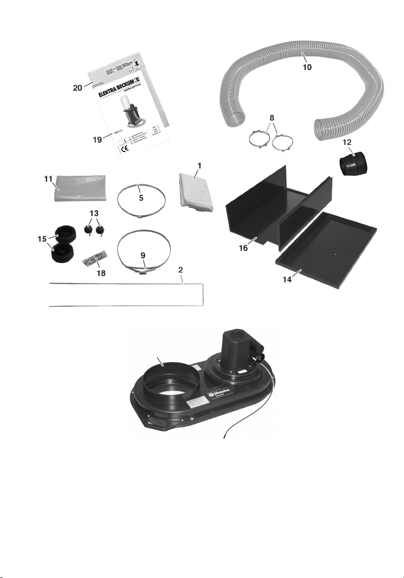
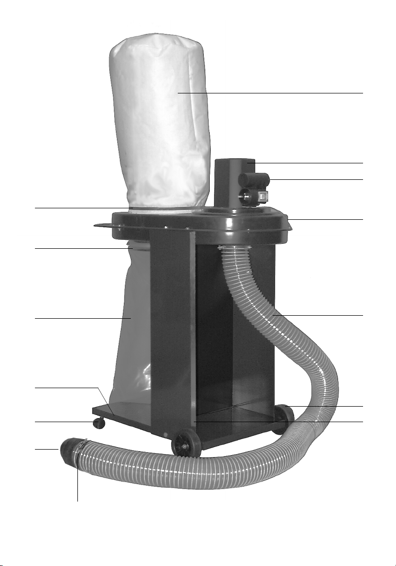
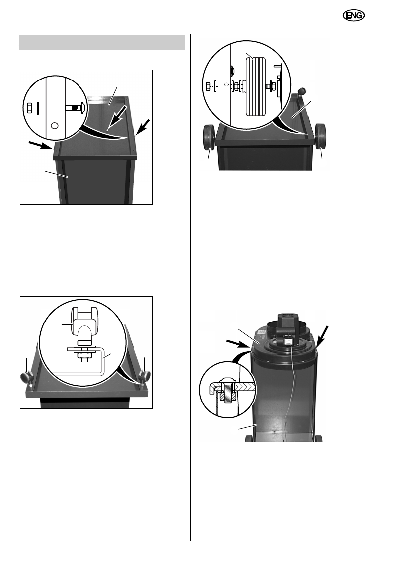
3 Appliance Components
1) Filter
3) 750 watt electric motor
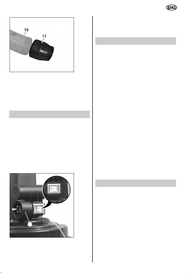
4) Combined switch/plug
5) Filter clamping band
6) Suction unit
8) Hose clamp
9) Chip bag clamping band
10) Suction hose
11) Chip bag
12) Connector
13) Castor
14) Base-plate
15) Wheel
16) Column
4 Safety Instructions
Read through these Operating
Instructions carefully and
thoroughly.
– The appliance must not be switched on until
it has been completely assembled.
– Extractor should only be operated if the
machine tools or cleaning nozzle are
connected.
– Solid bodies, e.g. pieces of wood (edge
longer than 10 mm), metal scraps and
stones etc. must not be vacuumed up.
Materials of this kind cause damage to the
fan impeller or the suction unit (rendering
guarantee claims null and void).
– Always disconnect the plug from the mains
supply before undertaking any maintenance
tasks, e.g. changing the bag, filter or hose,
so as to exclude any possibility of injury
caused by coming into contact with the
moving fan impeller.
– Keep the appliance dry. Do not vacuum up
any liquids.
– Do not use in any space where there is a
risk of explosion.
– Always check that the appliance is
operating properly before use.
– Do not use the appliance at temperatures
less than 0 °C. Do not vacuum up any
material which is at a temperature above
60 °C.
– The appliance must not be used by children
or any person who is not familiar with its
operation.
– Observe accident prevention and fire
prevention regulations.
– When changing the filter (1) or the chip bag
(11), a face-mask (filter-mask with particle
filter, filter class 2) must be worn to provide
protection from dust.
– Before changing the chip bag (11), tap the
filter (1) to dislodge deposits and clean.
– Where accessories are to be used, these
must be original manufacturer’s parts only.
The operator will render null and void any
claims arising if he uses the chip extractor
with anything other than original parts.
5 Proper Use
The chip extractor is designed for
extracting wood chips with a low
proportion of sawdust in connection
with wood-processing machines
(e.g. circular sawing machines, band
sawing machines, surface planing
and thicknessing machines and
vertical spindle moulding machines)
where these produce wood chips.
The appliance is not designed for vacuuming
up liquids. In addition, it should not be used for
the following materials: sharp-edged and
pointed objects (such as broken glass or nails)
or any material at a temperature above 60 °C.
The operator bears sole responsibility for any
damage caused by inappropriate use. The
generally recognised accident prevention
regulations and the “Safety Instructions” must
be observed.
The chip extractor is designed for non-
commercial use. Non-commercial use means
that the appliance is not used by employees,
persons undergoing professional training, in
schools, for domestic purposes, or by persons
in an employment relationship representing the
equivalent of work.
12
ENGLISH