IKA INC 125 FS digital User manual

INC 125 FS digital

3
ENGLISH

4 5
!
!
!
!
!
!
!
!
!
!
Fig. 1
Fig. 2

6 7
Installation�������������������������������������������������������������������������������������������������15
EU Declaration of conformity �����������������������������������������������������������������������7
Explication of warning symbols ��������������������������������������������������������������������7
!
Safety instructions����������������������������������������������������������������������������������������8
Unpacking �������������������������������������������������������������������������������������������������14
Operation ��������������������������������������������������������������������������������������������������31
Intended use����������������������������������������������������������������������������������������������11
Technical Data ������������������������������������������������������������������������������������������ 58
Maintenance and cleaning ������������������������������������������������������������������������ 56
Warranty �������������������������������������������������������������������������������������������������� 59
Useful information ������������������������������������������������������������������������������������ 12
Error codes ����������������������������������������������������������������������������������������������� 55
Accessories ����������������������������������������������������������������������������������������������� 57
Shaker platform ���������������������������������������������������������������������������������������� 57
Operator panel and display ����������������������������������������������������������������������� 28
Interfaces and outputs ������������������������������������������������������������������������������ 52
Setting menu navigation and structure������������������������������������������������������� 46
EU Declaration of Conformity
Source language: German
Explication of warning symbols
/// Warning symbols
Indicates an (extremely) hazardous situation, which, if not avoided, will
result in death, serious injury�
Danger!
Indicates a hazardous situation, which, if not avoided,
can result in
death, serious injury�
Warning!
Indicates a potentially hazardous situation, which, if not avoided, can
result in injury�
Caution!
!
Indicates practices which, if not avoided, can result in equipment damage�
Notice!
We declare under our sole responsibility that this product corresponds to the directives
2006/42/EG,
2014/35/EU, 2014/30/EU and 2011/65/EU and conforms with the following
standards or normative documents: EN 61010-1, EN 61010-2-010, EN 61326-1, EN 60529,
EN ISO 12100 and DIN 12880�
A copy of the complete EU Declaration of Conformity or further declarations of conformity can be
requested at sales@ika�com�
Dimensions����������������������������������������������������������������������������������������������� 59
Indicates a hazardous situation that cause from a hot surface!
Caution!
Indicates crushing risk to fingers / hands�
Caution!
Risk of biohazard infection�
Warning!

8 9
Safety instructions
/// General information
›
Read the operating instructions completely before starting up and follow the safety
instructions.
› Keep the operating instructions in a place where it can be accessed by everyone�
› Ensure that only trained staff work with the device�
› Follow the safety instructions, guidelines, occupational health and safety and accident
prevention regulations�
› The device must only be used in a technically perfect condition�
!Notice!
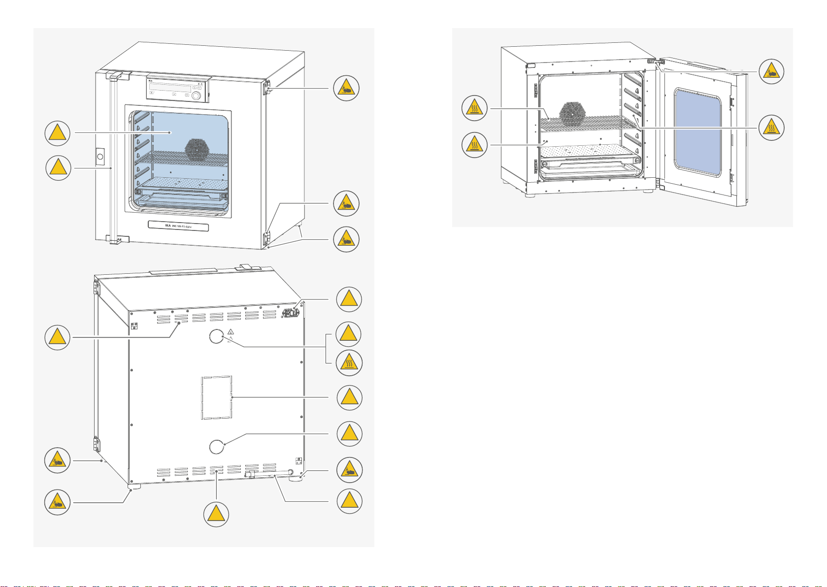
› Pay attention to the marked sites in Fig� 1 and Fig� 2�
!
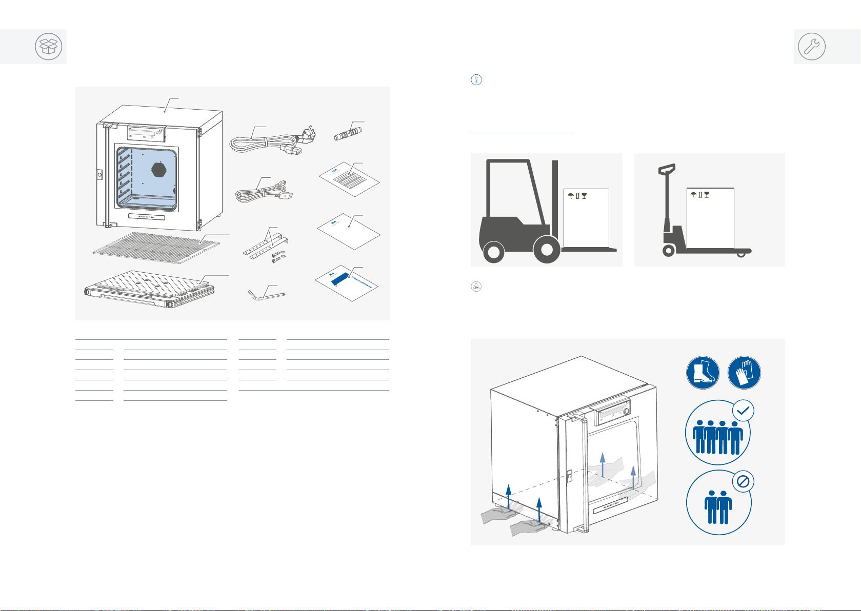
/// Transportation / Device setup
Danger!
› Beware of the high dead weight of the device when transporting�
Caution!
› Ensure that your fingers do not get crushed when setting down the device�
Caution!
› The power switch of the device must be accessed immediately, directly and without risk at
any time� If access to the power switch cannot be ensured, an additional emergency stop
switch that can be easily accessed must be installed in the work area�
/// Working with the device
Danger!
› Do not use the device in explosive atmospheres, it is not EX-protected�
› To avoid body injury and property damage, observe the relevant safety and accident
prevention measures when processing hazardous materials�
Warning!
› Only process samples that will not react dangerously to the extra energy produced through
processing� This also applies to any extra energy produced in other ways, e�g� through light
irradiation�
› Do not start up the device if:
- it is damaged
- cable is damaged�
Warning!
› Risks may also be posed by biological or microbiological substances�
› Observe the national regulations for handling these substances, the biological security level
of your laboratory, the material safety data sheets and the manufacture's application notes�
›
For complete instructions on handling of germs or biological material in risk group II or higher,
please refer to the "Laboratory Biosafety Manual" (source: World Health Organization)�
Caution!
› There is a crushing risk when opening or closing the door� Keep your hands away from
squeezing edges�
Caution!
› The inner chamber, the glass window on the door and the door gasket may become hot
during operation� Do not touch these part during operation�
› Risk of burns caused by vapour or hot surface� Pay attention to the residual heat after
switching off the device�
Caution!
›
Media may only be processed or heated with this device in safe operation without monitoring
if their flash point lies above the set safety temperature limit� The set safety temperature limit
must be at least 25°C below the flash point of the medium in use (EN 61010-2)�
› The device must have cooled down before loading / unloading�
› Heavy loads can lead to tilting of the device� Observe loading recommendations for the
shelves�
› Do not move any loaded racks�
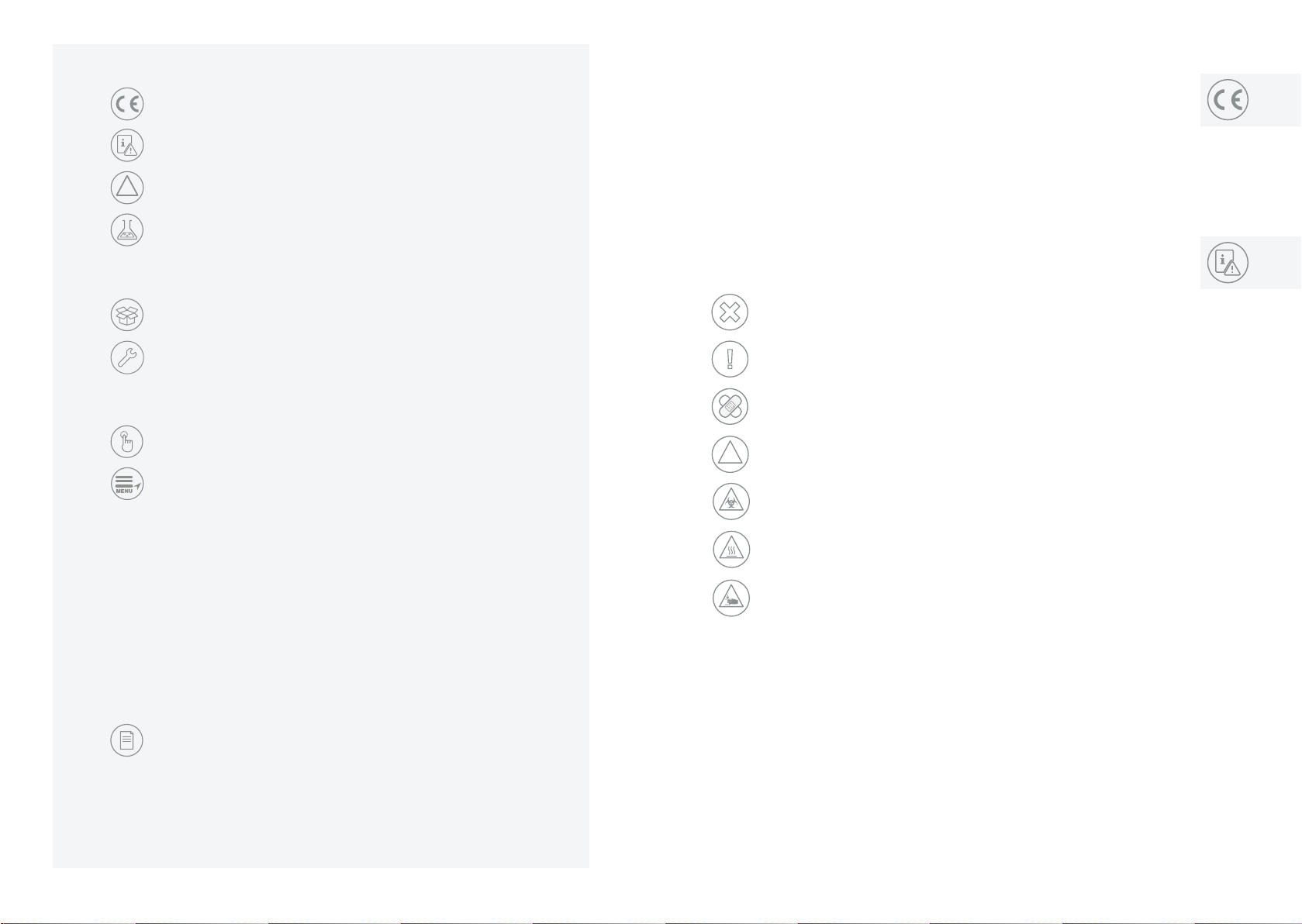
/// General Symbols
Position number
A–––
Correct / Result!
Shows the correct execution or the result of an action step�
Wrong!
Shows the incorrect execution of an action step�
Note!
Displays action steps that require particular attention to detail�
Closed lock
Indicates the status of “locked”�
Open lock
Indicates the status of “Unlocked”�
!Notice!
› Set up the device in a spacious area on an even, stable, clean, non-slip, dry and fireproof
surface�
› The feet of the equipment must be clean and undamaged�
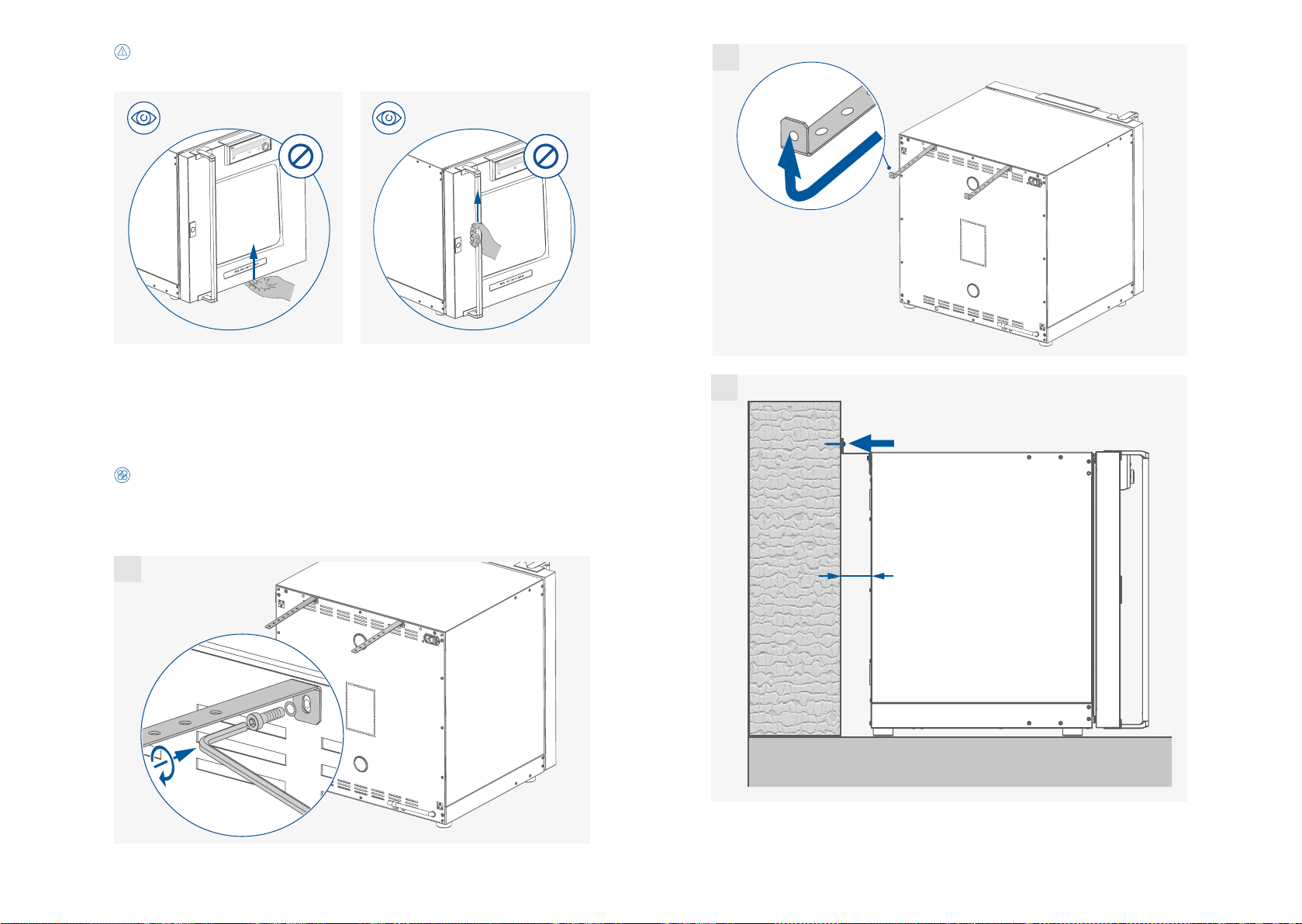
›
Ensure the anti-tilt bracket is properly fixed, in particular when the device is stacked�
›
Make sure that the ventilation slots are not blocked at back of the device�
›
Observe the minimum distances: between devices and wall min� 150 mm�

10 11
/// Disposal instructions
› The device, accessories and packaging must be disposed of in accordance with local and
national regulations�
/// Maintenance
› The device must only be opened by trained specialists, even during repair� The device must
be unplugged from the power supply before opening� Live parts inside the device may still
be live for some time after unplugging from the power supply�
Intended use
///
Use
The device is suitable for heating / shaking of non-explosive, non
-flammable or harmless
substance and objects� It is also suitable for drying e�g� glassware or warm storing
of liquids in
container�
Due to the highly precise temperature control, the device is especially suitable for incubation of
cultures at a standard temperature of 37 °C�
Note: The device must only be used for heating up non-explosive and non-flammable
substances and objects� Do not process substances or objects that might cause explosive vapour�
The device is not classified as a medical device as defined by Medical Device Directive�
/// Range of use
Indoor environments similar to that a laboratory of research, teaching, trade or industry�
The safety of the user cannot be guaranteed:
›
if the device is operated with accessories that are not supplied or recommended by the
manufacturer�
›
if the device is operated improperly or contrary to the manufacture’s specifications�
›
if the device or the printed circuit board are modified by third parties�
/// Power supply / switching off the device
› The voltage stated on the type plate must correspond to the power voltage�
› The device can only be disconnected from the power supply by pulling out the power plug
or the connector plug�
› The device must only be operated with the original power cord set�
› The socket for the power cord must be easily accessible�
› Socket must be earthed (protective ground contact)�
› After a power failure during operation, the device may start automatically (depending on
operating mode)�
› Disconnect the power plug before cleaning, maintenance and transportation of the device�
/// Accessories
Caution!
› Use the locking brake when using the roller frame or roller box�
› Protect the device and accessories from bumping and impacting�
› Check the device and accessories beforehand for damage each time when you use them�
Do not use damaged components�
› Safe operation is only guaranteed with the accessories described in the ”Accessories” section�
› Only use IKA approved accessories�
› Use only original IKA spare parts�
!Notice!
› Covers or parts that can be removed from the device without tools must later be refitted to
ensure safe operation� This will prevent the infiltration of foreign objects, liquids and other
contaminants�
› Never use the device for:
- heating food
- drying living beings
- heating room
› Pay attention to the vessels on the shaker platform when setting the shaking speed� This
will prevent any of the medium to be shaken from spurting out of the sample vessels�
› If the shaking vessels break during operation or the media be spilt, interrupt the shaking
process immediately, remove any vessel residue and clean the device�
› All accessories and vessels in place for the shaking process must be firmly secured�
› Shaking vessels which are not properly secured could get damaged or be projected out� It
is essential to regularly check that the vessels to be shaken and the attachments are firmly
secured, especially before using the device again�
› Avoid allowing objects to push or strike the shaker platform�

12 13
3-point calibration and offset
Factory Calibration
Resulting Offset Graph
Offset < 10 K
Deviation between offset points > 30 K
Point 1
-5K
Point 2
+7K
Point 3
+5K
100
[ºC]
80
60
40
20
0
Useful information
/// Material
The inner chamber of the device is made of high quality stainless steel� The window on the door
is made of tempered glass�
Note: Do not heat substances containing acids and halogenoids with this device!
/// Air flow
In recirculation mode, the fan gently and evenly distributes the temperature in the incubator�
The supply air coming from outside is guided through the vents into the inner chamber and
preheated in the working chamber�
/// Temperature monitoring
The device has a temperature limiter (TB) class 1 according DIN 12880� This means that in case
of a single failure the device is switched off at 150 °C� The temperature may be higher for a
short time in the area of the heater and on the walls� So beware of risk of fire or explosion of
unsuitable load�
Note: Any component of the heating / drying material must not be able to release toxic gases�
/// Calibration and adjustment
Individual load and ambient condition might influence the temperature behaviour of the
chamber� To compensate that influence there’s the option to neutralize by using the 3-point
calibration and offset function� This function allows the temperature to be calibrated and
adjusted at three different temperature values�
Use a calibrated reference meas
uring device in case of adjustment�
The operation can be done at a single, or up to three temperature levels:
Point 1: Temperature calibration and adjustment at low value of temperature�
Point 2: Temperature calibration and adjustment at medium value of temperature�
Point 3: Temperature calibration and adjustment at high value of temperature�
This menu shows how the values can be entered after the respective temperatures are
approached and with an external measuring device cross-checked (calibrated)�

14 15
Unpacking
›
Please unpack the device carefully�
› Any damage should be notified immediately to the shipping agent (post oce, railway
network or logistics company)�
1 INC 125 FS digital
2Shelf
3SP 20 shaking platform
4Power cord set
5USB cable
6Tilt protections
7Hexagon socket offset screw key
8Hose adapter
9Calibration certification
10 User guide
11 Warranty card
IKA RC 2 lite
Garanty
1+2+3
CalibrationCerficate
1
4
10
11
6
5
9
2
3
7
8
Caution!
›
Ensure that your fingers do not get crushed when setting down the device�
›
For lifting the device, four people are required�
›
You may get your hands or feet squashed when transporting and setting down the device�
Wear protective gloves and safety boots�
Installation
/// Transportation / setting down the device
Warning!
›
Beware of the high dead weight of the device when transporting�
›
The device should only be transported by qualified persons with suitable handling
equipment, such as a pallet truck and forklift!
The device can be transported:
- With a forklift truck - With a pallet truck�

16 17
!Notice!
When lifting the device, do not use the door / door handle� This may damage the device�
/// Setting up / Fixing the device to the wall
› Place the device on an even, clean, dry and fireproof surface in well-ventilated environment�
› Keep sufficient distance to radiators and other heat sources�
› Keep at least 150 mm between walls and the device�
Caution!
Fixation against the wall is compulsory!
As indicated in following figures, attach the device to a wall with the tilt protections included
with the device� Fasten the tilt protections to the rear side of the device with included
hexagon socket screws and screw key�
1
2 x
Note: The screws used for fixing is selected according to the wall conditions and is not included�
2
3
min. 150 mm

18 19
/// Placing the drain hose in laboratory drain
› Take off the hose from the bracket
In the event of glass vessels breakage, the leaked liquid is collected by the drain pan (not
included in delivery scope) below the shaker platform and is guided to the drain hose� Place
the drain hose in laboratory drain�
Note: The extension hose is not included in delivery scope�
› Extend the drain hose with included hose adapter as necessary
/// Inserting the shaker platform and shelf
› Open the door
› Insert the shaker platform
Note: When assembling the shaker platform, ensure the shaker platform locking knobs are
turned to unlock status�
2

20 21
Note: When assembling the shaker platform, ensure the shaker platform coupling (A) is inserted
into the coupling (B) correctly in the device�
A
› Lock the
shaker
platform
/// Correctly loading
› Insert the shelf

22 23
/// Connecting to power
!Notice!
The socket used must be earthed (fitted with earth contact)�
Observe the ambient conditions (temperature, humidity etc�) listed under “Technical Data”�
2.
1.
!
220 - 240 V ~
50/60 Hz
750 W
IP 20
Note: The voltage stated on the type plate must correspond to the power voltage�
For loading, pull out the shaker platform to a maximum of halfway�
Note:
› Don't load sample directly on the shaking platform�
› Keep distance between samples and hot inner surface� Temperature of the inner wall may
be much higher than set temperature�
› Ensure sucient air circulation in the chamber by not placing the sample too close�

24 25
/// Other installation information (Stacking two devices)
›
Fixing the bottom device to the wall (see section "Setting up / Fixing the device to the wall")
Caution!
When stacking the device, four persons are required to lift it�
Never stack more than two devices�
› Place the top device
› Fixing the top device to the bottom device
2 x
1
6 x
2

26 27
› Fixing the top device to the wall
Note:
› The screws used for fixing is selected according to the wall conditions and is not included�
› The stacking kit is not included� Please order it separately�
2 x
› Placing the drain hoses in laboratory drain
Take off the hose from the bracket
Extend the drain hose with included hose adapter as necessary
2
The devices drain hoses must be guided to the laboratory drain with the hose adapters and
extension hoses�
Note: The extension hoses are not included in delivery scope�
1

28 29
Operator panel and display
Item Designation Function
ADisplay Screen�
BMenu button Press it once: menu option is display
Press it once again: back to working screen�
CLock button Lock / unlock the settings�
DStandby button Switch on / off the device�
EStandby LED The light LED indicates the device is in standby status�
FMultifunction button Switch between shaker (SHAKE), fan (FAN) and light (LIGHT) setting�
GTimer button Switch between "Counter (C)" and "Timer (T)", "Timer Auto (Ts)"
setting�
HControl knob
(rotating / pressing)
Adjust the temperature setting�
Adjust shaking speed (rpm) / fan speed (%) and light mode�
Adjust time value in Timer (T) or Timer Auto (Ts)�
Navigation, selecting and changing the settings�
Start / stop running of the device�
A
BC
HG
F
E
D
/// Explanation of the control elements /// Explanation of symbols on the working screen
12
345 6 789
17
16
10
15
14
1211 13
Item Designation Function
1Temperature value Display the settings and actual temperature value�
2"Set"
symbol
Indicate the temperature set value is shown on the display�
3
Fan symbol
Indicate the fan is activated�
4
SHAKE / FAN / LIGHT symbol
Indicate the selected function (shaker / fan / light)�
5Door symbol
Indicate the door is opened�
6Light symbol Indicate the light is activated�
7Operating mode symbol Indicate the device is in operating mode (A, B or C)�
8Lock button symbol
Indicate the settings of the device is locked�
9USB connection symbol
Indicates a USB cable is connected�
10
Time range Indicate the selected timer / counter range ([d:h:min] or [h:min:sec])
11
Heating Symbol Indicate the heating function is activated�
12
Temperature control symbol
Indicate the selected temperature control mode (a PID or f PID)�
13
Shaker platform symbol
Indicate the shaker platform is assembled�
14 SHAKE / FAN speed
Display the shaker speed (rpm) or fan speed (%)�
15
Timer / counter value
Display the timer / counter value�
16 Counter symbol Indicate the counter is activated�
17 Timer symbol
Indicate the timer is activated�

30 31
/// Switching on
Operation
/// Setting the temperature
Min.
Max.

32 33
/// Setting the shaker speed / fan speed / light
› Switch between shaker /fan / light
...
Note:
Switching between the shaker / fan and light function by touching the multifunction
button (F)� The selected function blinks� Then, the value can be adjusted respectively by rotating
the control knob (H)�
› Adjust the shaker speed
Min.
Max.
Note:
When the device is running, the shaker speed can also be adjusted�

34 35
› Confirm the setting of shaker speed › Adjust the fan speed value
Min.
Max.
Note:
› The fan speed value can also be adjusted during the device running�
› Higher fan speed can improve the temperature homogeneity in the chamber�

36 37
› Confirm the setting of the fan speed value and start the fan › Adjust the light setting
Note: When the device is running, the light status can also be changed�

38 39
› Confirm the light setting and activat the light
indicates the light is set to "on (On)" status�
indicates the light is set to "Auto (AUT)" status� When the door is opened, the light is
switched on automatically and this symbol appears�
Note:
/// Setting Counter (C) / Timer (T) or Timer Auto (Ts)
› Switch between Counter (C) /Timer (T) / Timer Auto (Ts)
...
Table of contents
Popular Accessories manuals by other brands

SPX
SPX Marley LW032 B Series user manual

Texecom
Texecom Mirage Dual Technology Installation instructions manual

Energizer
Energizer Step 1 quick start guide

SICK
SICK WLL80 Analog operating instructions

WAREMA
WAREMA Photo 623 067 Operating and installation guide

STIL
STIL CHR 150 Operating and maintenance manual