Ikegami ICD-848 User manual

Ikegami Tsushinki Co., Ltd.
INSTRUCTION MANUAL
MODEL
ICD-848
Color–B/W Camera
OUTDOOR USE WARNING
WARNING – TO PREVENT FIRE OR
ELECTRIC SHOCK, DO NOT
EXPOSED THIS APPLIANCE TO
RAIN OR MOISTURE.

2
Thank you very much for your wise choice of the Ikegami Color CCD Camera. Please carefully read this
Instruction Manual to keep your camera at full capacity.
Page
1. Handling precautions .................................................................................................................. 1
2. General ....................................................................................................................................... 1
3. Features ...................................................................................................................................... 1
4. Names of Parts and their functions ............................................................................................. 2
5. Setting ......................................................................................................................................... 5
5-1. User setting ........................................................................................................................ 5
5-2. Setting switches and their functions ................................................................................... 5
5-3. User setting menus ............................................................................................................ 5
6. Specifications .............................................................................................................................. 7
7. Warranty and after-sale service .................................................................................................. 9
8. Setup Menu
Contents
CAUTION:
TO REDUCE THE RISK OF ELECTRIC
SHOCK, DO NOT REMOVE COVER (OR BACK)
NO USER-SERVICEABLE PARTS INSIDE REFER SER-
VICING TO QUALIFIED SERVICE PERSONNEL.
The lightning flash with arrowhead symbol, within an equilateral triangle, is intended to alert
the user to the presence of uninsulated "dangerous voltage" within the product's enclosure
that may be of sufficient magnitude to constitute a risk of electric shock to persons.
The exclamation point within an equilateral triangle is intended to alert the user to the pres-
ence of important operating and maintenance (servicing) instructions in the literature accom-
panying the appliance.
NOTE:
This equipment has been tested and found to comply with the limits for a Class A digital device,
pursuant to Part 15 of the FCC Rules. These limits are designed to provide reasonable protection
against harmful interference when the equipment is operated in a commercial environment. This
equipment generates, uses and can radiate radio frequency energy and, if not installed and used in
accordance with the instruction manual, may cause harmful interference to radio communications.
Operation of this equipment in a residential area is likely to cause harmful interference in which case
the user will be required to correct the interference at his own expense.
CAUTION;
ANY CHANGES OR MODIFICATIONS NOT EXPRESSLY APPROVED BY THE PART RESPON-
SIBLE FOR COMPLIANCE COULD VOID THE USERS AUTHORITY TO OPERATE THE EQUIP-
MENT.
CAUTION
RISK OF ELECTRIC SHOCK
DO NOT OPEN

1
1. Handling precautions
(1) Do not open the case of camera and never touch inside, where precision parts are assembled. A trouble
or accident may result.
(2) Do not install the unit where it is exposed to water splash, high humidity and heavy dust. Internal parts
may be damaged.
(3) Be very careful not to drop or shock the camera.
(4) Never touch the CCD surface.
2. General
The ICD-848 is a single CCD color/B/W changeover CCTV camera that employs a 1/2-inch CCD (Charge
Coupled Devise) with about 380,000 picture elements. One set of camera can give a high-quality color
picture in daytime and B/W picture at night. The unit features high resolution, high sensitivity and high picture
quality, and is equipped with many functions: back-light compensation, automatic electronic shutter, auto-
matic iris control and others. The cameras are best suited for general-purpose monitoring.
3. Features
(1) Day/Night selecting function
(2) Digital processing
(3) High-quality picture and high resolution
(4) Equipped with back-light compensating function
(5) 2-way automatic iris controlling function
(6) Automatic white balance
(7) AES (Automatic Electronic Shutter)
(8) Flange focal distance adjusting mechanism

2
4. Names of parts and their functions
MAX40mA
LENS
DC VIDEO
COLOR V I DEO CAMERA
Digi tal
COLOR V I DEO CAMERA
F
O
CUS
LOCK
Digi tal
U
D
LR
SET UP
GENLOCK I N
V I DEO OUT
RENOTE
AC2 4 V
DC1 2 V
CL A SS 2
• • Hz
• • • •
• • • •
1 2
POWER
E
HIGH 75Ω
~
-
+
A VIEW
(LEFT VIEW)
(TOP VIEW)
(RIGHT VIEW)
(BACK VIEW)
A
(AC24V/DC12V)
8 9
10
11
16
18
12
15
14
1713
2
76
1
5 4 3

3
①Lens mount (CS mount)
Accepts many types of CS mount lenses.
②C mount adaptor (Accessory)
Attached to the lens mount to accept many types of C mount lenses.
③Flange focal distance adjuster
Used to adjust the flange focal distance depending on the type of lens used. Helpful when the lens’focus
ring fails to put into focus.
④Flange focal distance lock screw
Used to mechanically lock the flange focal distance after fine adjustment of it.
⑤Holder screw hole
Used to mount the camera onto the camera holder. Effective for general camera tripods.
Note:
Be sure to use less than 5.5mm- long setscrew (1/4”–20 UNC) for mounting the camera to tripods or
holder.
⑥Lens selector switch
Used to choose between the video iris and the DC iris depending on the type of auto iris lens used.
⑦Auto iris lens connector
Specifically used to connect the auto iris lens. Use the connector plug that is attached to the camera.
• For video type auto iris lens
Set the lens selector switch to VIDEO position.
—Connector cable leads —
1. Red (power)
2. Not used
3. White (video)
4. Black (shielded)
* Dress the tip of the green lead to prevent a short-circuit.
• For the DC type auto iris lens
Set the lens selector switch to the DC position.
—Connector cable leads —
1. Damping coil (–)
2. Damping coil (+)
3. Driving coil (+)
4. Driving coil (–)
* Connect the leads as shown above. Refer also to the instructions of the lens.
Auto iris lens
24
13
Auto iris lens
24
13
Number of connector pins
2
4
1
3

4
⑧-⑫Camera setting function switches
Use them by referring to each operation item.
⑬Video output terminal
Used to give out the video signal. Connect this to the video input terminal of a monitor, switcher etc. (To
be terminated with 75-ohm impedance.)
⑭External sync signal input terminal
Used to receive the GENLOCK (general lock) signal. For external synchronization, input VBS or BBS
signal.
⑮External sync signal 75-ohm termination switch
Set to HIGH position when the GENLOCK signal is looped with T-shaped connector. Usually, set at 75-
OHM position.
⑯Power indicator
Green LED lights up when power is supplied to the camera.
⑰Remote terminal
Used to input the sensor for Day/Night selection filter.
⑱AC 24V/DC 12V power input terminal
Feed AC 21.6-26.4V or DC10.5-28V power.
This installation should be made by a qualified service person and should conform to all local codes.

5
5. Setting
5-1. User setting
On this camera, user can make settings of picture quality, synchronization, identification etc. by himself or
herself. The setting menus are on-screen character display. (Refer to 8. Setup Menu.)
5-2. Setting switches and their functions
On the back of the camera there are the
pushbutton switches and display as
shown at the left.
Switch name Main function
UP switch (U): Setting item selection (up)
DOWN switch (D): Setting item selection (down)
RIGHT switch (R): Setting change and setting item selection (right)
LEFT switch (L): Setting change and setting item selection (left)
ENTER (E): Setting mode call on/off, setting entry
5-3. User setting menus
(1) CAMERA ID Up to 16 characters can be accepted and displayed.
Switching on and off the CAMERA ID function and presetting ID code
characters.
(2) DAY/NIGHT For selection of daytime/night monitoring
AUTO: Day/Night selection luminance level is set automatically.
REMOTE:
MAKE: Changes to Night (B/W) mode by closing terminal.
BREAK: Changes to Night (B/W) mode by opening terminal.
COLOR: Day (COLOR) mode
B/W: Night (B/W) mode
(3) SHUTTER Setting of high-speed electronic shutter
Selection of high-speed shutter, display of the screen at VARABLE mode
(4) LIGHT CONT. Selection of AES or auto iris lens
Setting of back-light compensation as sub-menu
(5) GAIN Selection of AGC, HYP-AGC and fix
(6) WHITE BAL. Selection and setting of white balance system
ATW1: 2600K-6000K
ATW2: 2000K-6000K(when sodium lamp is used.)
AWC: PUSH SET
MANU: MANUAL SET
(7) SYNC Selection of synchronization system (INT, LL)
(It is impossible to select LL when the power is not synchronous.)
GENLOCK is selected automatically.
(GENLOCK is not displayed without external sync signal.)
It is possible to adjust the phase on sub-menu.
U
SET UP
D
E
LR

6
(8) MENU LOCK Setting procedure is locked. (Unlocking: U →R→D→L→U→D→E)
•Setting Indications and functions common on the setting menu
(1) EXIT Ending (Saving) the setting mode and returning to the regular display.
(2) CANCEL Recalling the previously saved settings.
(3) RESET Recalling the factory-settings.
(4) RET Returning to the preceding setting menu.
Select one of these indications and press the E switch.
•Special menu MATRIX
Use the camera usually in A mode. When using the camera indoors or under
fluorescent light, B mode is recommended.

7
6. Specifications
(1) Imaging device: 1/2-inch interline transfer type
Effective pixels: 768 (H) x 494 (V), about 380,000 pixels
Color filter: Color difference line sequential system
(2) Scanning system: 2:1 interlace, as per NTSC system
(3) Vertical sync frequency: 59.94 Hz
(Corresponding to power frequency for line-lock)
(4) Horizontal frequency: 15.734 kHz
(Varies with power frequency for line-lock; SC not synchronized)
(5) Synchronizing system: Internal sync: Crystal lock or line lock (on AC type only)
External sync: GENLOCK (Automatic selection)
(6) GENLOCK input: VBS or VS; 1.0 Vp-p/75 ohms (High impedance selectable)
BBS; 0.45 Vp-p/75 ohms (High impedance selectable)
(7) Video output: VBS; 1.0 Vp-p/75 ohms
(8) Horizontal resolution: 480 lines
(9) S/N ratio: 52 dB (p-p/rms) or more
(Luminance signal, standard illumination, DETAIL correction OFF, weighting
circuit ON)
(10) Minimum illumination: In COLOR mode: 0.15 lux/F1.4 (AGC ON)
In B/W mode: 0.015 lux/F1.4 (AGC ON)
(11) AGC: ON (AGC, HYPER-AGC)/OFF (LOW, MID, HIGH) selectable
(12) White balance: ATW/AWC/MANUALAL selectable and adjustable
(13) DETAIL correction: Provided (Detail level adjustable)
(14)
Back-light compensation:
ON/OFF/SPOT selectable, compensation level adjustable
(BLC)
(15) AES (Automatic : ON/OFF selectable
Electronic Shutter) AES range: About 1:1600 (Inoperable in a region where the power frequency
and the camera’s vertical sync frequency are different from each other.)
(16) Electronic shutter: OFF, 1/100, 1/125, 1/250, 1/500, 1/1000, 1/2000, 1/4000, 1/10000, VARIABLE
(Selectable among 1/60-1/100000)
(17) Auto iris function: VIDEO iris/DC iris selectable (Changeover type)
(18) Camera ID function: Provided (One line, 16 characters)
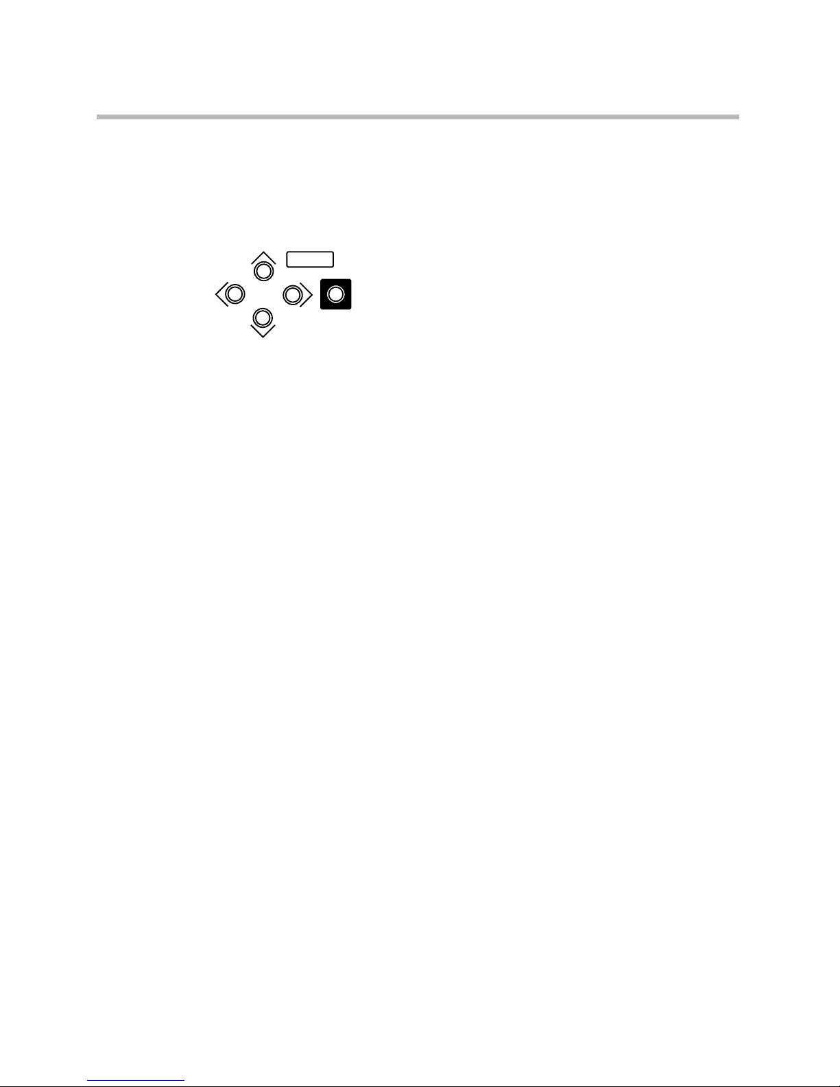
(19) Local setting functions: Selectable and adjustable with on-screen display using 5 control buttons; Cam-
era ID, DAY/NIGHT mode and level selection, AES/electronic shutter, BLC ON/
OFF/SOPT selection and level adjustment, DC iris level, INT/LL, external sync
frequency phase adjustment, DETAIL level, AGC ON/OFF, ATW/AWC/MANU
selection and adjustment, CHROMA level, PED. level, menu lock selectable.
(20)
Remote setting functions:
Possible (Multiplex video communication system with RCU-701)
Same presettable items as with the local setting functions
(21) Lens mount: CS mount (C mount adaptor attachable)
(22) Flange focal distance: Provided
adjusting mechanism
(23) Power supply: AC 24V ±10%, 60 Hz/DC 12V (10.5-28V)
(24) Power consumption: Approx. 5W

8
(25) Working ambient: -10 to +50˚C/30-85% RH (No dew condensation)
temperature/humidity
(26) Camera mount: 1/4”-20UNC (Also mountable on top)
(27) External dimensions: 64(W) x 54(H) x 120(D) mm (No projections and accessories included)
(W x H x D)
(28) Weight Approx. 580g
(29)
Input/Output connectors
:•VBS output BNC
•GENLOCK input BNC
•Lens 4-pin (Applicable plug: E4-191J-100)
•DAY/NIGHT changeover input 2-pin push-in terminal
•AC 24V/DC 12V input 2-pin push-in terminal
(30) Accessories: •Instruction manual 1
•C mount adaptor (CMA-40) 1
•Auto iris lens connector plug 1
(E4-191J-100 or equivalent)
(31) Options: •Remote control unit (RCU-701)
Multiple transmission type remote set-up unit using camera’s video output
cable. Many settings and functions can be remote-controlled by this unit.
※The specifications and appearance may be subject to change without prior notice.

9
7. Warranty and after-sale service
A warranty accompanies this product. Read and fill out the warranty card that you have received at your
dealer. Keep this card in a safe place.
•Please consult Ikegami Electronics (U.S.A.), Inc. or your dealer for full warranty information. Your dealer
will repair or replace free of charge within the warranty period according to the warranty coverage.
•For repairs after the expiration of the warranty period, consult your dealer or sales representative. It will
first be judged whether the trouble is repairable or not. Charged servicing will then be made upon the
request of user.
•Before you ask for servicing, take trouble of reading the Instruction Manual. If the unit still fails, take note
of the model number, date of purchase, problem etc. in detail, and inform your dealer or sales represen-
tative.
•If you have questions about the after-sale service, contact your dealer or sales representative.
※We suggest you ask for preventive inspection earlier.

2
8. Setup Menu
SETUP MENU
PUSH E
FOR A WHILE
CAMERA ID OFF
TOP 3RD
2ND
ON
OFF
ON
*
POSITION
RET +E
+E EXIT +E
AUTO
OFF
LIGHT CON. LENS
1/100 (1/60)
1/125
1/250
1/500
1/1000
1/2000
1/4000
1/10000
VARIABLE
B/W
SWITCHED LEVEL
CONTROL SIGNAL
+E
+E
AES +E
+E *ADJUST +D
MAKE +D
BREAK +D
RET +E EXIT +E
*ADJUST
1/60 (1/50) - 1/100000
+D RET +E EXIT
IRIS LEVEL *ADJUST
*ADJUST
*ADJUST
+E
U
D
LR
U
D
LR
U
D
LR
U
D
LR
U
D
LR
U
D
LR
U
D
LR
*
ALPHANUMERIC
RET +E EXIT +E
+E EXIT +E
RET +E EXIT +E
REMOTE
COLOR
BLC LEVEL
BLC LEVEL *ADJUST
*ADJUST
ON
OFF
SPOT
IRIS LEVEL
WIDE BLC
IRIS LEVEL
RET
SPOT SET +E *ADJUST
SHUTTER
DAY/NIGHT

3
GAIN LOW
SYNC
AUTO-CHANGE
INT
MID
HIGH
AGC
WHITE BALANCE
ATW1
ATW2
AWC PUSH
MANUAL
HYP-AGC
+E
+E
MENU LOCK
OFF +E
+E
*TRACKING
ON
+URDLUDE
R GAIN *ADJUST
B GAIN *ADJUST
COARSE *ADJUST
FNE *ADJUST
RET +E EXIT +E
EXT VBS
EXR VS RET +E EXIT +E
+E EXIT +E
LL
EXT VBS H.PHASE *ADJUST
SC COARSE
*ADJUST
SC FNE
*ADJUST
+E EXIT +E
H.PHASE *ADJUST
CHROMA *ADJUST
DETAIL *ADJUST
PEDESTAL *ADJUST
MATRIX A MODE
B MODE
+E EXIT +E
EXIT
CANCEL +E
RESET
SPECIAL MENU
+E *
DEFAULT
RET +E EXIT +E
EXT VS
*
BEFORE SETTING
PUSH L
AND R
AT ONCE
RET
RET
RET

Ikegami Tsushinki Co., Ltd.
Printed in Japan.
K28295
■Ikegami Electronics (U.S.A.), Inc.
37 Brook Avenue, Maywood, New Jersey 07607, U.S.A.
Phone: (201) 368-9171, FAX 201-569-1626
■Ikegami Electronics (Europe) GmbH
Ikegami Strasse 1, 41460 Neuss 1, F.R. Germany
TEL. 02131-123-0/FAX 02131-102820
■Ikegami Electronics (Europe) GmbH U.K. Branch
Unit E1 Cologne Court Brooklands Close,
Windmill Road Sunbury-on-Thames Middlesex TW16 7EB, UK
TEL. 01932-769700/FAX 01-92-769710
Other manuals for ICD-848
1
Table of contents
Other Ikegami CCTV Camera manuals