Ikegami ISD-A21 User manual

Ikegami Tsushinki Co., Ltd.
INSTRUCTION MANUAL
MODEL
OUTDOOR USE WARNING
WARNING – TO PREVENT FIRE OR
ELECTRIC SHOCK, DO NOT
EXPOSE THIS APPLIANCE TO
RAIN OR MOISTURE.
ISD-A21
Color Camera
e
c
o
p
r
o
d
u
c
t
s

Thank you very much for your wise choice of the Ikegami DPS Camera. Please carefully
read this Instruction Manual to keep your camera at full capacity. This DPS camera is
equipped with a 1/3” DPS CMOS sensor.
Page
1. Handling precautions ............................................................................... E-1
2. General .................................................................................................... E-1
3. Features ................................................................................................... E-2
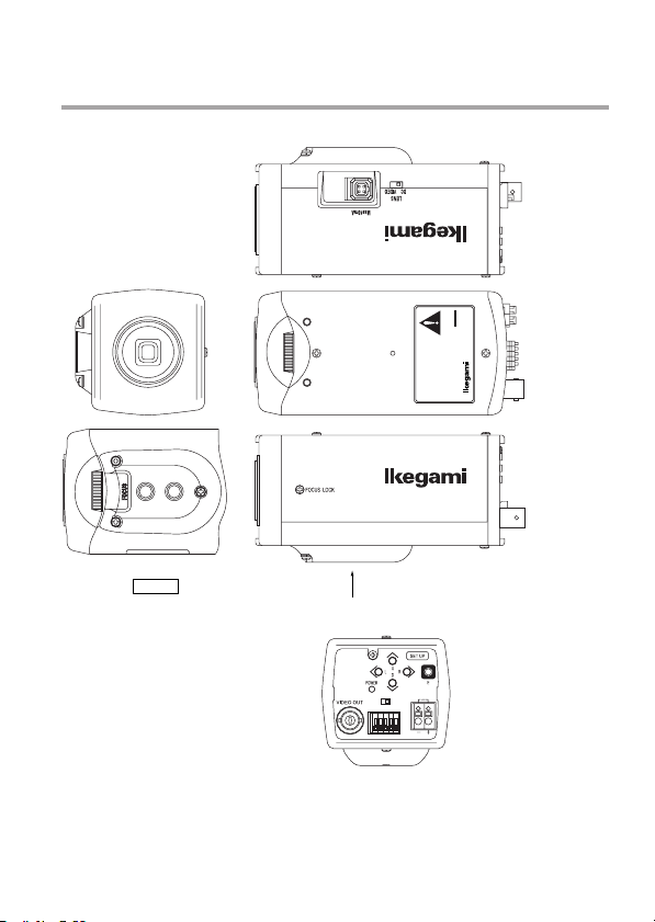
4. Names of parts and their functions .......................................................... E-3
5. Operation ................................................................................................. E-5
5-1. User setup ....................................................................................... E-5
5-2. SETUP switches and their functions ............................................... E-6
5-3. Entering the setup mode and its basics .......................................... E-6
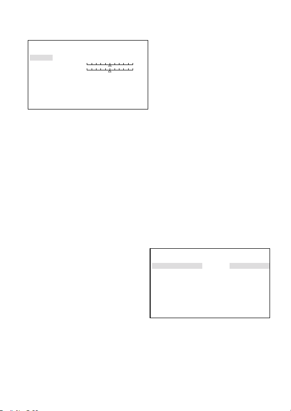
5-4. Setup procedures ............................................................................ E-7
6. Warranty and after-sale service ............................................................... E-15
7. Specifications ........................................................................................... E-16
8. Appearance View
9. Setup Menu
Contents
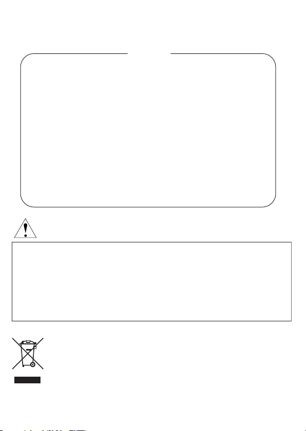
The exclamation point within an equilateral triangle is intended to alert the user to the presence of
important operating and maintenance (servicing) instructions in the literature accompanying the
appliance.
NOTE:
This equipment has been tested and found to comply with the limits for a Class A digital device,
pursuant to Part 15 of the FCC Rules. These limits are designed to provide reasonable protection against
harmful interference when the equipment is operated in a commercial environment. This equipment
generates, uses and can radiate radio frequency energy and, if not installed and used in accordance with
the instruction manual, may cause harmful interference to radio communications. Operation of this
equipment in a residential area is likely to cause harmful interference in which case the user will be required
to correct the interference at his own expense.
CAUTION;
ANY CHANGES OR MODIFICATIONS NOT EXPRESSLY APPROVED BY THE PART RESPONSIBLE
FOR COMPLIANCE COULD VOID THE USERS AUTHORITY TO OPERATE THE EQUIPMENT.
Instructions for Disposal of Electric and Electronic Equipment in Private Household
Disposal of used Electric and Electronic Equipment
(Applicable in the European Union and other European countries with separate
collection systems)
This symbol on the product, or in the related documents in the package, indicates that this
product shall not be treated as normal household waste. Instead, it should be taken to a proper
applicable collection point or depot for the recycling of electric and electronic equipment.
By ensuring this product is disposed of correctly, you will help prevent possible negative consequences for the
environment and human health, which could otherwise be caused by inappropriate waste handling of this
product. The recycling of materials will help to conserve natural resources.
For more detailed information about recycling of this product, please contact your local city authority, your
household waste disposal service or the place where you purchased the product.

E-1
1. Handling precautions
• Do not install the camera in a water-splashed or highly humid place.
• Do not use the camera where the ambient temperature drops below -10°C or rises
above +50°C. The images and component parts may be adversely affected or the
camera may get in trouble.
• Never open the case of the camera because there are precision parts inside.
Otherwise a trouble or accident may result.
• Do not put anything metallic and other foreign substances through the vent. A trouble,
fire or electric shock may result.
• Be sure to turn off the power before installing or making connections.
• Do not install the camera in places exposed to vibrations and shocks.
• Be very careful not to drop or shock the camera while carrying it in.
• Do not touch the imaging device
• Do not orient the camera to the sun.
• Some types of lenses may cause hunting, light amount drop or other problems. In
such case, readjust the lenses.
* Because of the digital image device characteristics, images may look rugged at high
temperatures. This does not mean the camera is in trouble.
2. General
This color camera is provided with a 1/3-inch DPS CMOS sensor. The CCTV camera
features wide dynamic range, high sensitivity and high resolution, and is equipped with
the color/black-and-white switching, back-light compensation, automatic iris control, line
lock and other functions. The unit is best suited for general surveillance.
Also equipped with the RS-485 communication function, the unit can be used to build an
advanced surveillance system.
3. Features

E-2
(1)Wide dynamic range (WDR)
The WDR function provides for backlight compensation in a wide dynamic range.
Being shot even in wide-illumination-fluctuating spots, bright-and-dark subjects can
be captured clearly and in a natural look.
(2)Day/night switching function
High-quality color images are captured by day, whereas high-sensitivity monochrome
pictures are taken at night. This automatic switching provides for crisp pictures without
afterimage around the clock. Combined with an external sensor or the like, the switching
pattern can also be controlled.
(3)Automatic white balance
Thanks to the automatic follow-up white balance control (ATW), the white balance
adjusts itself no matter how greatly the subject's color temperature fluctuates.
(4)High-quality picture and high resolution
The camera is designed for smear-free imaging and low noise. The DSP (Digital Signal
Processor) effectively enhances details, which achieves crisp and sharp images with
high signal-to-noise ratio. The high resolution is backed up by a horizontal resolution
of 520 TV lines and a vertical resolution of 400 TV lines.
(5)High sensitivity
Various modes of automatic gain control (AGC) are available to finely adjust the camera
settings depending on the subject's illumination conditions. With the AGC and slow
shutter in combination, high sensitivities of up to 0.03 lux/F1.4 are achieved.
(6)Camera setup function
The control buttons on the back of the camera enable to change and save the camera's
settings.
(7)Two-way automatic iris control
This function is available to switch between video type iris lens and DC type iris lens.
In other words, almost all types of CCTV automatic iris lenses can be employed.
(8)Flange focal distance adjusting mechanism
This mechanism makes it easy to readjust the focus tracking when a zoom lens is
used.
(9)RS-485 communication function
The RS-485 communication function lets an external PC or the like control the camera,
which helps configure an advanced surveillance system.
(10) Monitor selection function
The optimum picture quality can be selected according to the monitor used (CRT or
LCD).

E-3
4. Names of parts and their functions
A VIEW
A
COLOR CAMERA
MODEL
TYPE
SER.NO.
IKEGAMI TSUSHINKI CO., LTD.
MADE IN JAPAN
AC24V 50/60Hz 280mA/DC12V 275mA
REV.
ISD
-
A21
TERM
RS
-
485
OFF ON
GND
-
+
-
+
CLASS2
AC24V50/60Hz280mA
DC12V275mA
(LEFT VIEW)
(TOP VIEW)
(RIGHT VIEW)
(BACK VIEW)

E-4
①Lens mount (CS mount)
This is used to mount the lens on the camera. Many types of CS mountlens can be
attached.
②Flange focal distance adjuster
Used to readjust the flange focal distance (distance between lens mounting face and
imaging area), if the camera fails to come into focus with the lens’ focus ring.
③Focus lock screw
Used to lock the camera’s flange focal distance after is has been readjusted.
④Holder mounting screw holes
These holes are used to fix the camera on the camera holder. They are also applicable
to general tripods.
Note
To attach the camera on a tripod or a camera holder, be sure to use mounting
screws. (1/4" -20UNC) that are shorter than 5.5 mm.
⑤Lens selector switch
The switch has two positions, for a video iris lens and a DC iris lens.
⑥Auto iris lens connector
Specifically used to connect the auto iris lens.
•For the video type auto iris lens
Set the lens selector switch to VIDEO position.
— Connector cable leads —
1. Red (power)
2. Not used
3. White (video)
4. Black (shielded)
*Dress the tip of the green lead to prevent a short-circuit.
•For the DC type auto iris lens
Set the lens selector switch to DC position.
— Connector cable leads —
1. Damping coil (-)
2. Damping coil (+)
3. Driving coil (+)
4. Driving coil (-)
* Connect the leads as shown above.
Refer also to the instructions of the lens.
Auto iris lens
3
2
1
4
Auto iris lens
3
2
1
4

E-5
⑦- ⑪Camera setup function switches
Refer to the Operation chapter.
⑫Video output terminal (VIDEO OUT)
Used to give out the video signal. Connect this to the video input terminal of a monitor,
switcher etc. (To be terminated with 75-ohm impedance.)
⑬Power indicator (POWER)
The LED indicator stays on in green while the camera power is on.
⑭Terminal switch for RS-485
In RS-485 communication control, turn this switch to ON side for one-to-one control,
and turn it to OFF side for daisy-chain connection. (For use in daisy-chain connection,
turn ON the terminal switch by terminal connection equipment.)
⑮RS-485 connection terminal block
Used for RS-485 connection.
⑯DC12V/AC24V power input terminal
Keep the input power at DC10.5-15.0 V or AC24V±10%.
* This installation should be made by a qualified service person and should conform to
all local codes.
3
2
1
4
Numbers of connector pins
5. Operation
5-1. User setup
This camera can be user-preset for picture quality, synchronization, ID code and others.
The SETUP MENU is displayed in a tree view style, and the settings can be made using
onscreen characters.

E-6
5-2. SETUP switches and their functions
The pushbuttons and their markings at left are provided on the back
of the camera.
Up Switch (U) Used to select SETUP items (up and down).
Down Switch (D)
Right Switch (R) Used to modify the settings.
Left Switch (L)
Enter Switch (E) Used to enter and quit the setup mode and to save the settings.
* To enter the setup mode, hold down the E button longer than 2 seconds.
5-3. Entering the setup mode and its basics
5-3-1. SETUP MENU (Main menu)
Hold down the E button longer than 2
seconds, and the menu at left appears
onscreen. A highlighted item is now selected.
(1)CAMERA ID Up to 24 characters can be displayed onscreen.
(2)DAY/NIGHT The day (color) or night (B/W) mode is selected.
(3)LIGHT CONTROL
The backlight compensation and spot photometry modes are
selected. The wide dynamic level and DC type iris lens are adjusted.
(4)GAIN The gain control and electronic sensitivity up modes are selected.
The electronic sensitivity multiplying factor is also selected.
(5)WHITE BALANCE The white balance mode is selected. The manual white balance
settings are made.
(6)SYNC The sync systems (INT and LL) are selected and set up.
(7)MENU LOCK The saved settings can be locked.
(8)SETUP The EXIT, CANCEL or RESET action is selected and executed.
①EXIT: Used to save the settings and to quit the menu.
②CANCEL:
Used to return the settings to the previously saved ones.
③RESET: Used to return the settings to the factory ones.
* New settings are not saved if EXIT is selected to quit the menu.
U
SET UP
D
E
LR
SETUP MENU
→CAMERA ID OFF
DAY/NIGHT AUTO
LIGHT CONTROL
GAIN
WHITE BALANCE ATW
SYNC INT
MENU LOCK OFF
SETUP EXIT

E-7
5-3-2. SPECIAL MENU
Highlight EXIT on the SETUP MENU
screen. Hold down the L and R buttons
together, and the screen at left appears
onscreen.
(Page 1/2 shown at left)
(1) PAGE Selection of page 1/2 or 2/2.
(2) CHROMA Used to adjust the chroma level.
(3) DETAIL Used to adjust the details.
(4) SETUP Used to select the setup levels (0 IRE and 7.5 IRE).
(5) MONITOR Selection of monitor CRT or LCD
(6) RESOLUTION Used to select the NORMAL or HIGH resolution mode.
(7) DNR Switching on and off of noise reduction.
(8)
VIDEO STANDARD
Used to switch between the video signal systems (NTSC/PAL).
(9) COLOR BAR Used to turn on and off the color bars.
(10)PROGRES.SCAN Used to select the Interlace or Progressive mode.
(11) RS-485ID
Used to preset an ID number (1 thru 207) for RS-485 communication.
(12) RET Used to go back to the main menu screen.
5-4. Setup procedures
5-4-1. CAMERA ID
(1)CAMERA ID ON/OFF setting
Highlight CAMERA ID. Using the E, L
or R button, access the ON/OFF
setting. Decide the ON or OFF setting
with the L or R button.
SPECIAL MENU V1.00
→PAGE 1/2
CHROMA
DETAIL
SETUP 7.5IRE
MONITOR CRT
RESOLUTION NORMAL
DNR OFF
RET
SETUP MENU
→CAMERA ID OFF
DAY/NIGHT AUTO
LIGHT CONTROL
GAIN
WHITE BALANCE ATW
SYNC INT
MENU LOCK OFF
SETUP EXIT

E-8
(2)ID characters setting
Keep CAMERA ID highlighted and press
the E button. The screen at right shows up.
①ID
Press the E button on ID, and the
cursor appears. With the L or R
button, select a character. Press the
E button to save it, and the character
box advances to the next one. To
delete a character, press the E button to go through the code and place the cursor
in the character to delete. Press the L or R button to get the box blank.
②ID ALL CLEAR
Highlight this item and press the E button. The ID code is cleared.
③ID POSITION
Highlight this item and press the L or R button. In this way, the ID code can be
positioned up or down.
④RET
Press the E button to go back to the main menu screen.
5-4-2. DAY/NIGHT
(1)With the L and R buttons, make the
AUTO, COLOR or B/W setting.
①AUTO
Automatic switching is made: high-
quality color images during the day,
and high-sensitivity monochrome
pictures at night. Press the E button,
and the screen at right shows up.
• B/W BURST
The burst signal for black-and-white pictures can be selected ON or OFF.
• SWITCHED LEVEL
The brightness level for switching to the day or night mode can be preset. With the
L and R buttons, the levels are selected in the order of BRIGHT, MID and DARK.
• LIGHT
Select “IR” when an infrared illumination or the like is used. Select “NORMAL” in
other cases.
②COLOR
The color mode is fixed.
③B/W
The black-and-white mode is fixed. Press the E button in this mode, and the menu
opens up and the “B/W BURST” setting can be made like in ①above.
ID EDIT
→ID.....................
ID ALL CLEAR
ID POSITION UP
RET
DAY/NIGHT AUTO
→B/W BURST ON
SWITCHED LEVEL DARK
LIGHT NORMAL
RET

E-9
5-4-3. LIGHT CONTROL
(1)Select LIGHT CONTROL on the main
menu screen. Press the E button, and
the screen at right shows up.
*The IRIS LEVEL item appears only
when the lens selector switch at the
camera's back is set at DC.
(2)BACKLIGHT CMP.
Highlight this item and the backlight
compensation modes can be selected (ON, 1SPOT, 2SPOT and OFF).
①ON
Usual backlight compensation is made.
②1SPOT
Select “ISPOT” and press the “E” button,
and the screen shown at right appears.
Highlight “ADJUST ZONE” and press
the “E” button, and the photometric
range setting screen shows up.
Each time the E button is pressed, the
photometric frame color turns blue,
green and red in this order.
• Blue
Using the U, D, L or R button, the
field can be moved wherever you like.
• Green
Using the U, D, L or R button, the
field can be enlarged.
• Red
Using the U, D, L or R button, the field can be reduced.
* To quit the field setting screen, hold down the E button longer than 2 seconds.
Once the 1SPOT ZONE screen appears, select RET and press the E button. The
previous menu shows up.
③2SPOT
As with the 1SPOT mode, two photometric fields can be preset. Take the same
procedure as for the 1SPOT mode.
④OFF
The backlight compensation function is off.
1SPOT ZONE
→ADJUST ZONE
RET
SPOT ZONE−1 ENT:2SEC→RET
LIGHT CONTROL
→BACKLIGHT CMP. OFF
W.DYNAMIC
IRIS LEVEL
LENS IRIS AUTO
RET

E-10
(3)W. DYNAMIC
The wide dynamic level can be varied with the L and R buttons. The intermediate
level is initially set. In shooting scenes with greatly fluctuating light quantities, move
the marker to the right to get a higher effect. Position the marker while watching an
actual scene.
(4)IRIS LEVEL
This item appears when the DC type iris lens is in use. Move the marker to the
right, and the lens aperture gets opener (Brightness enhanced). Position the marker
while watching an actual scene.
(5)LENS IRIS
Select the lens’ iris control system. (AUTO, MANUAL)
①AUTO
The automatic iris lens control function is enabled.
②MANUAL
This is selected with a manual iris lens in use. White saturation at high
illumination is suppressed. In other words, too bright a subject can be reproduced
rather clearly than usual.
(6)RET
Press the E button to go back to the main menu screen.
5-4-4. GAIN
(1)Select GAIN on the main menu screen. Press the E button, and the screen at right
shows up.
(2)GAIN
With the L and R buttons, the gain control
modes can be selected.
①AGC
This is an automatic sensitivity
adjustment mode. Select AGC and
press the E button, and maximum
gain setting can be achieved. To
suppress the noise lower than at the HIGH (initial) setting, select MID or LOW.
②HYP-AGC
This mode is higher in sensitivity than AGC. But images may look rugged at higher
sensitivities.
③LOW : This fixed-gain mode keeps the sensitivity low for brighter spots.
④MID : This fixed-gain mode keeps the sensitivity middle between HIGH and LOW.
⑤HIGH : The fixed-gain mode keeps the sensitivity high for darker spots.
GAIN
→GAIN AGC
SENS UP OFF
SLOW SHUTTER x2
RET

E-11
(3)SENS UP
The electronic sensitivity up modes can be selected with the L and R buttons.
At all the positions but OFF, the automatic gain control function turns on itself.
The HYP-AGC mode can also be switched on.
①OFF (initial setting)
②S/N
The signal-to-noise ratio priority mode is used in shooting subjects that vary in
brightness and move slightly.
③STD
The standard mode is used in shooting subjects in brightness-changing spots to
suppress both blurry images and rugged looks.
④MOVE
The motion priority mode is used in shooting subjects that vary in brightness and
move greatly like on the street and in parking lots.
* Note: With the sensitivity multiplying factor at maximum, the motion-dependent
blurriness and ruggedness look the same in all the 3 modes.
* Note: In the S/N, STD or MOVE mode, the gain control levels LOW, MID and HIGH
cannot be selected.
(4)SLOW SHUTTER
The electronic sensitivity multiplying factor can be adjusted with the L and R buttons.
x2, x4, x8, x16, x32
The higher the factor, the higher the sensitivity, but motions at maximum factor look unnatural.
5-4-5. WHITE BALANCE
The white balance mode is selected. The manual white balance settings are made.
(1)The white balance modes can be switched with the L and R buttons.
①ATW (initial setting)
White balance is automatically followed up.
②ATW Ex
White balance is automatically followed up, but the color temperature range gets
higher than the ATW mode. Compared with the ATW mode, color fading may be
caused under usual light sources.
③AWC
This is the so-called one-push automatic white balance control. Shoot a target white
subject and press the E button, and the white balance will be adjusted.
④MANUAL
Select MANUAL, press the E button
and the screen at left appears
onscreen.
R GAIN is used to adjust the reddish
shades.
B GAIN is used to adjust the bluish
shades.
WHITE BALANCE
→R GAIN
B GAIN
RET

E-12
SYNC LL
→PHASE
+90DEG
RET
5-4-6. SYNC
(1)The INT and LL modes can be
selected with the L and R buttons.
(2)INT
The internal sync mode is selected.
(3)LL
The line lock mode is selected. Press the
E button, and the screen at right shows
up.
①PHASE
With the L or R button, move the marker to finely adjust the phase.
②+90DEG
With the E button, the phase angle can be adjusted to 0°, 90°, 180°or 270°in the
increment of 90°.
③RET
Used to go back to the main menu screen.
5-4-7. MENU LOCK
The menu lock function protects saved settings against accidental modifications.
(1)Locking
Get the saved settings locked with the L and R buttons.
(2)Operation
When locked, EXIT alone is effective and all the other actions are inoperative.
(3)Unlocking
Press the U, R, D, L, U, D and E buttons in this order. If a wrong button is pressed
halfway, start all over again.
5-4-8. SPECIAL MENU
(1)Highlight SETUP on the main menu
screen and hold down the L and R
buttons together. The SPECIAL MENU
screen at right shows up.
SPECIAL MENU V1.00
→PAGE 1/2
CHROMA
DETAIL
SETUP 7.5IRE
MONITOR CRT
RESOLUTION NORMAL
DNR OFF
RET

E-13
(2)PAGE
Pages can be selected with the “L” and
“R” buttons.
(3)CHROMA
With the L and R buttons, the chroma level can be adjusted. Make the adjustment to
your desired level while watching an image on screen.
(4)DETAIL
With the L and R buttons, the details can be adjusted. Make the adjustment to your
taste while watching an image on screen.
(5)SETUP
With the L and R buttons, the setup level can be selected: 0 IRE and 7.5 IRE.
(6)MONITOR
The optimum picture quality can be selected according to the monitor used (CRT or
LCD).
①CRT
Used when the camera is connected with a CRT (cathode ray tube) monitor.
②LCD
Used when the camera is connected with an LCD monitor.
(7)RESOLUTION
With the L and R buttons, the resolution can be selected.
• NORMAL
Natural-looking images are captured. (recommended)
• HIGH
High-resolution images are captured. They may look glaring depending on the types
of subjects.
(8)DNR
The noise reduction function can be switched on and off.
SPECIAL MENU V1.00
→PAGE 2/2
VIDEO STANDARD
COLOR BAR
PROGRES.SCAN OFF
RS−485ID 1
RET

E-14
WARNING!!
If the setting of the
video standard is changed,
all the settings are
initialized.
Do you change the setting?
→CANCEL
OK
SELECT VIDEO STANDARD
→VIDEO STANDARD NTSC
RET
(9)VIDEO STANDARD
The video signal systems (NTSC/PAL)
are switched here. Select VIDEO
STANDARD, press thee button and the
warning screen at right shows up.
* Note: Select a video signal system
according to your TV system. If the
selection is wrong, no or distorted
images may result. This does not
mean the camera is in trouble.
①CANCEL
Used to go back to the SPECIAL
MENU screen.
②OK
Used to go to the SELECT VIDEO
STANDARD screen. (See at right.)
Highlight VIDEO STANDARD. With
the L or R button, the NTSC and PAL
systems can be switched each other.
* Each time another system is selected, the current settings will be back to their
factory.
Select RET, and the SPECIAL MENU screen reappears.
(10) COLOR BAR
Press the E button to get the color bars displayed. Press the E button again to go back
to the SPECIAL MENU screen.
(11)PROGRES.SCAN
①OFF
Interlace mode output. Normal operation should be use at OFF.
②ON
Progressive scan mode output. When it connects to Frame Recording DVR, it
should be use at ON. It will be reduced blurring of moving subject when it plays
recorded images by DVR. However it will be shutter speed of 1/30 seconds, output
video images from camera will be unnaturalness images with quick moving subject.
(12)RS-485ID
With the L and R buttons, an ID number (1 thru 207) can be preset.
(13)RET
Used to go back to the main menu screen.
5-4-9. Communication with control device (RS-485)
The camera can be controlled from a control terminal (PC, for example). For details,
refer to the Communications Specifications.

E-15
6. Warranty and after-sale service
A warranty accompanies this product. Read and fill out the warranty card that you have
received at your dealer. Keep this card in a safe place.
• Please consult Ikegami Electronics (U.S.A.) Inc. or Ikegami Electronics (Europe)
GmbH or your dealer for full warranty information. Your dealer will repair or replace
free of charge within the warranty period according to the warranty coverage.
• For repairs after the expiration of the warranty period, consult your dealer or sales
representative. It will first be judged whether the trouble is repairable or not. Charged
servicing will then be made upon request of the user.
•Before you ask for servicing, take trouble of reading the Instruction Manual. If the
unit still fails, take note of the model number, date of purchase, problem, etc. in
detail, and inform your dealer or sales representative.
•If you have questions about the after-sale service, contact your dealer or sales
representative.
* We suggest you ask for preventive inspection earlier.

E-16
7. Specifications
(1) Imaging device: 1/3-inch DPS CMOS sensor
(2) No. of effective pixels: Approx. 390,000 pixels, 720(H) x 540 (V)
(3) Scanning system: NTSC: 525 TV lines/59.94 Hz (60 Hz with Line-Lock ON),
2 : 1 interlace
(4) Sync system: INT/LINE-LOCK (phase adjustable) (Line-lock not usable
where the power frequency and the camera’s vertical
frequency are different from each other or when the
camera is DC-driven)
(5) Video output: VBS 1.0 Vp-p/75 ohms
(6) Resolution: Horizontal; 520 TV lines
(in high-resolution mode, at rated illumination)
(7) S/N ratio: Over 50 dB/rms (in normal mode, AGC OFF, Detail OFF
and Weighting ON )
(8) Minimum subject illumination: In color mode;
1.0 lux/F1.4 (video output 50%, HYPER-AGC)
In B/W mode;
0.2 lux/F1.4 (video output 50%, HYPER-AGC)
0.1 lux/F1.4 (video output 25%, HYPER-AGC)
(9) WDR function: Variable at 36 levels
(10) AGC: ON (AGC, HYPER-AGC)/OFF (LOW, MID, HIGH) selectable
(11) Electronic sensitivity up: Automatic (up to 32 times: interlocked with AGC mode)
(12) White balance: ATW/ATWex/AWC/MANU selectable
(13) Noise reduction: ON/OFF switchable
(14) Monitor selection: CRT/LCD switchable
(15) Day/night switching: Automatic/Manual switchable
(16) Auto iris function: Compatible with VIDEO iris and DC iris
(switchable, with DC iris level adjuster)
(17) Camera ID: Up to 24 characters (alphanumeric and symbols)
(18) Local setup: Selectable and adjustable with on-screen display using
pushbuttons; camera ID, AGC ON/OFF, ATW/AWC/MANU
selection and adjustment, LL/INT switching, phase
adjustment, wide dynamic range level, iris level, spot area
setting, electronic sensitivity up ON/OFF, DNR ON/OFF,
monitor selection CRT/LCD, detail level, chroma level,
day/night mode switching and level
(19) Remote setup: Possible (control with RCU-701/RCU-801 or RS-485)
Same presettable items as with the local setup

E-17
(20) Lens mount: CS mount
(21) Flange focal distance Provided
adjusting mechanism:
(22) Power supply: AC 24 V ±10%, 50/60 Hz, DC 12 V (10.5 – 15 V)
(23) Power consumption/current: AC 24 V; Approx. 280 mA
DC 12 V; Approx. 275 mA
(24) Ambient operating -10 to +50°C, 30 to 90%RH (no dew condensation)
temperature/humidity:
(25) Camera mount: 1/4” -20UNC (top and bottom mountable)
(26) Outer dimensions: 62(W) x 55(H) x 122(D) mm (no projections included)
(27) Weight: AC 24 V/DC12 V; Approx. 420 g
(28) Input/output connectors: • VIDEO OUT; BNC
• LENS; 4P (applicable plug E4-191J-150 or equivalent)
• DC 12V/AC 24V input; 2-pin terminal block
• RS-485 input/output; 5-pin terminal block
(29) Accessories: Instruction Manual, 1 copy
* Specifications and design are subject to change for product improvements without
notice.

Muchas gracias por haber elegido sabiamente la cámara DPS de Ikegami.
Lea cuidadosamente
este manual de instrucciones para mantener su cámara en las mejores condiciones de funcionamiento.
La cámara DPS está equipada con un sensor DPS CMOS de 1/3”.
Pàgina
1. Precauciones de manejo ......................................................................... S-1
2. Generalidades ......................................................................................... S-1
3. Características ......................................................................................... S-2
4. Nombres de las partes y sus funciones ................................................... S-3
5. Ajuste ....................................................................................................... S-5
5-1. Ajuste del usuario ............................................................................ S-5
5-2. Conmutadores de ajuste y sus funciones ....................................... S-6
5-3.
Entrada en el modo de configuración y sus puntos básicos .........................
S-6
5-4. Procedimientos de configuración .................................................... S-7
6. Garantía y servicio postventa .................................................................. S-15
7. Especificaciones ...................................................................................... S-16
8. Appearance View
9. Setup Menu
Indice
El signo de exclamaci n dentro de un tri ngulo equil tero tiene la finalidad de avisar al usuario de
la presencia de instrucciones de funcionamiento y mantenimiento (reparaciones) importantes en los
manuales que acompa an al aparato.
NOTA:
Este equipo ha sido probado y ha demostrado cumplir con los l mites establecidos para los dispositivos digitales de
la clase A, de conformidad con el Apartado 15 de las normas de la FCC. Estos l mites han sido establecidos para
proporcionar una protecci n razonable contra la interferencia perjudicial cuando el equipo se utiliza en un ambiente
comercial. Este equipo genera, utiliza y puede radiar energ a radioel ctrica, y, si no se instala y utiliza seg n las
indicaciones del manual de instrucciones, puede causar interferencias perjudiciales en las comunicaciones por
radio. El funcionamiento de este equipo en una zona residencial causar probablemente interferencias
perjudiciales, en cuyo caso, el usuario tendr que eliminarlas corriendo el mismo con los gastos pertinentes.
AVISO:
CUALQUIER CAMBIO O MODIFICACI N NO APROBADA EXPRESAMENTE POR LA PARTE RESPONSABLE DEL BUEN
FUNCIONAMIENTO DEL APARATO PODRŒA ANULAR LA AUTORIZACI N DEL USUARIO PARA UTILIZAR EL EQUIPO.
Instrucciones para eliminar equipos eléctricos y electrónicos de una casa privada
Eliminación de equipos eléctricos y electrónicos usados
(Normas aplicables en la Unión Europea y en otros países europeos con diferentes
sistemas de recogida)
Este símbolo en el producto, o en los documentos relacionados, indica que este producto no
deberá ser tratado como un residuo doméstico normal. En cambio, deberá ser llevado a un
punto o lugar donde los equipos eléctricos y electrónicos sean recogidos para ser reciclados.
Asegurándose de que este producto sea eliminado correctamente, usted ayudará a impedir las posibles
consecuencias negativas sobre el medio ambiente y la salud humana que podrían ser causadas por el
manejo inapropiado de este producto como residuo doméstico. El reciclado de los materiales ayudará a
conservar los recursos naturales.
Para conocer una información más detallada acerca del reciclado de este producto, póngase en contacto con
las autoridades de su localidad, con su servicio de recogida de residuos domésticos o con el comercio donde
adquirió el producto.
Table of contents
Languages:
Other Ikegami CCTV Camera manuals