Ikelite DS160 User manual

Please read all instructions before using this product.
Instruction Manual
DS160 Strobe

2
TABLE OF CONTENTS
IKELITE DS160 ST OBE ..................3
Specifications ......................................3
Introduction ..........................................4
Starting Out..........................................4
Strobe Compatibility ............................4
Strobe Power ......................................4
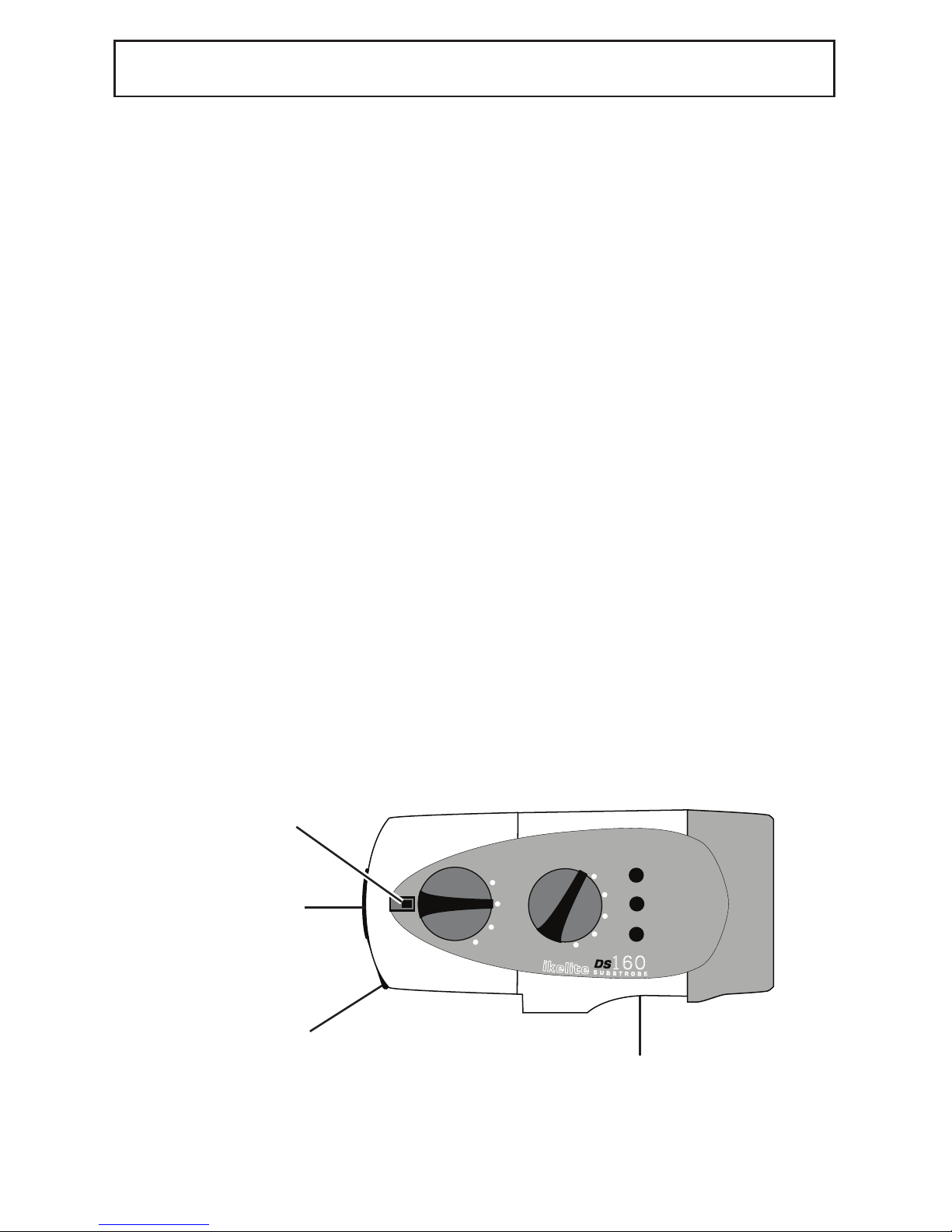
DS160 Strobe ......................................5
Overview of DS160 Features ..............5
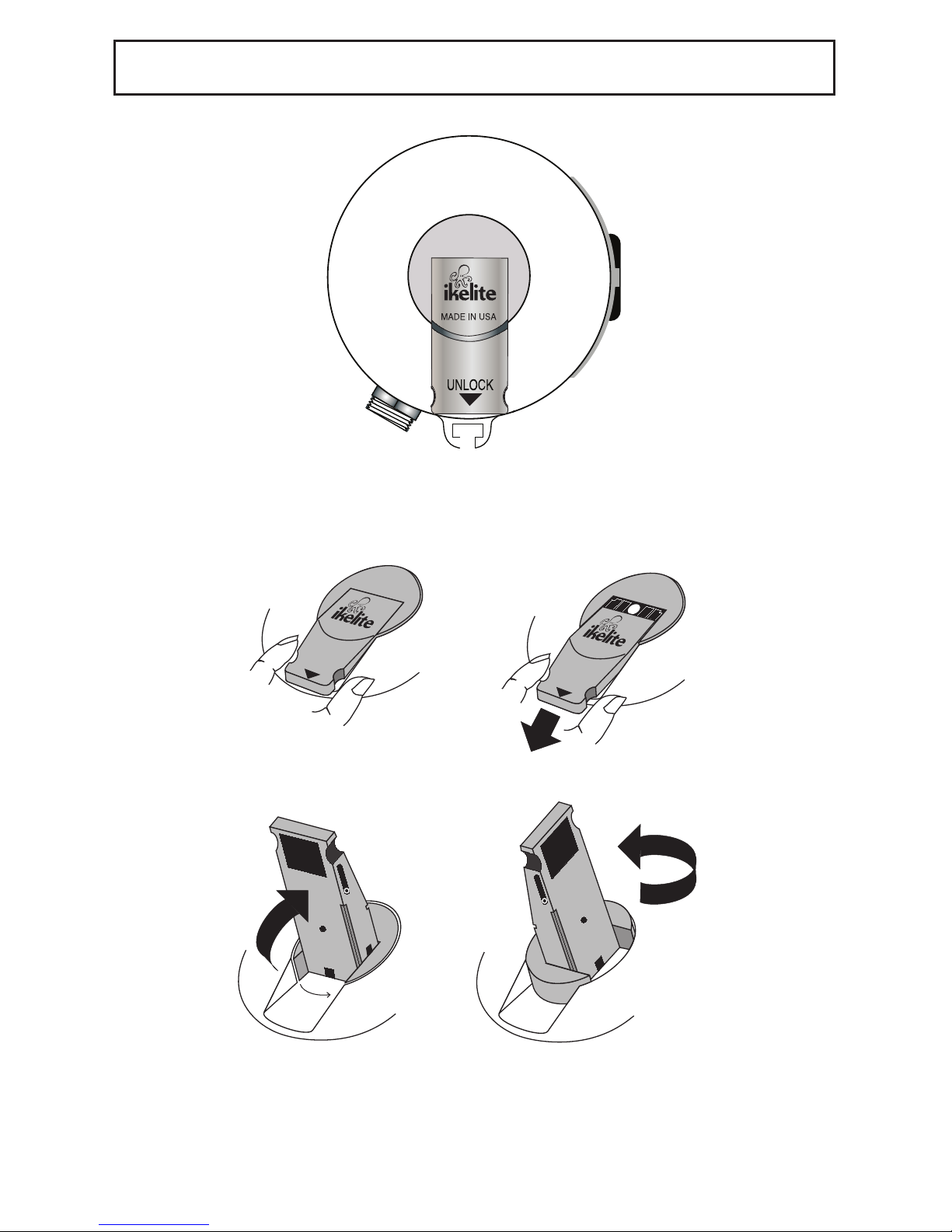
OPENING AND CLOSING ..................6
Opening the Strobe..............................6
O-ring ..................................................6
Closing the Strobe ..............................6
Opening and Closing (Illustration)........7
LI-ION BATTE Y PACK 4067 ............8
Charging the Battery Pack ..................9
Storage ................................................9
Warnings ..............................................9
Using NiMH or Ni-Cad Battery Packs ..9
SMA T CHA GE 4067.1 ................10
Specifications ......................................10
Includes................................................10
Usage ..................................................10
Warnings ..............................................10
FLASH DIFFUSE 0591.3 ..................11
Using the Diffuser ................................11
Diffuser Installation and Removal ........11
A M SYSTEMS/ST OBE MOUNTS ..12
Ikelite Arm Systems ............................12
Ikelite Mounts ......................................12
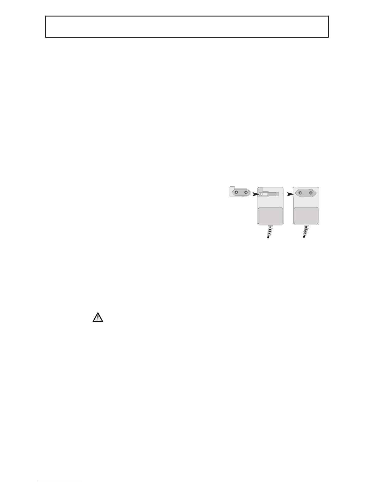
ST OBE CONNECTION ....................13
Strobe Connection (Illustration) ..........14
USING AS HA D-WI ED ST OBE ..15
USING AS HA D-WI ED ST OBE
WITHOUT TTL ....................................15
AIMING THE ST OBE........................16
SWITCHES / FUEL GAUGE ..............17
On/Off Switch ......................................17
Fuel auge ..........................................18
Confidence Signal................................18
Firing Mode Switch ..............................18
ST OBE EADY LIGHT ....................19
Strobe Ready Light and TTL Housing..19
Camera eady Light ..........................19
Triggered via Sync Cord ......................19
ECOMMENDATIONS........................20
Visual Inspections ................................20
Insurance ............................................20
Tips ......................................................20
Lubricant ..............................................20
MAINTENANCE ..................................21
Cleaning and Storage ..........................21
T OUBLESHOOTING ........................22
Strobe Will Not Fire..............................22
AI LINE T AVEL ..............................23
TECHNICAL SUPPO T ......................23
LIMITED WA ANTY ........................23
P ODUCT EGIST ATION ..............24

DS160 SPECIFICATIONS
CE - Compliant with applicable EU directives
Complies with FCC part 15, subpart B, Section 15.109 for Class “B” Products
S p e c i f i c a t i o n s
Battery Pack ............................................Li-ion module, 7.4v, 4500mAh
Weight ....................................................2.5 lb (1130g)
Size..........................................................9.6 cm dia. x 17.9 cm (3.75 in dia. x 7 in)
Depth Rating............................................90m - 300 feet
S t r o b e
Energy Rating..........................................160 watt-sec
Recycle Time ..........................................1.4 sec
Angle of Coverage ..................................90 degrees....... 100 degrees with diffuser
uide # (ISO 100) feet ............................76 surface - 38 underwater
uide # meters ........................................24 surface - 12 underwater
Color Temperature ..................................4800 degrees Kelvin
Full Power Flashes ..................................450 flashes per full charge
Firing Modes............................................TTL, Full, 9 fractional powers
Modeling Light
Modeling Light ........................................5-watt LED
TTL
Full
-2
-1
-3
-4
ReadyLight
Fuel
Gauge
3
2
1
Test
O
On
On
w /Lite
Switch Lock
Toggle
Li-ion Battery Pack
DS160 Strobe Head
3
IKELITE DS160 ST OBE

INT ODUCTION
Thank you for purchasing an Ikelite Strobe. Ikelite brings over 50 years of underwater
photographic and lighting experience to the strobe market. Ikelite Strobes are designed
and built in the USA by Ikelite to suit both the professional and the amateur photographer.
The purpose of a strobe is to illuminate the subject and assist the camera in taking vivid
pictures. The Ikelite DS160 Strobe is equally suited for general and wide-angle
photography, covering up to a full 100° angle with a diffuser.
The contents of this instruction manual are subject to change at any time without prior
notice.
STA TING OUT
Before using the Ikelite DS160 Strobe, please read this owner’s manual thoroughly and
retain it for future reference. Fully charge your strobe’s battery pack prior to your first use.
Ikelite recommends becoming familiar with the features and functions of the Ikelite DS160
Strobe above water before trying the camera and strobe in the water. And, if you have not
yet done so, it is suggested that you read your camera owner’s manual as well.
ST OBE COMPATIBILITY
The DS160 Strobe is compatible with all Ikelite TTL systems and current digital cameras,
as well as all older TTL film cameras including the Nikonos system. A variety of sync
cords, sensors, and TTL adapters are available to connect to almost any camera system
currently on the market.
ST OBE POWE
The DS160 recycles in a quick 1.4 sec from full discharge. When fired at a fractional
power — whether in TTL or manual mode — the strobe recycles virtually instantaneously.
Number of flashes per full charge will increase dramatically in most cases when using in
TTL mode with a compatible camera system. The powerful DS160 is adjustable in 10
half-stop increments for precise control over your exposure when used in manual mode.
IKELITE DS160 ST OBE (continued)
4

5
IKELITE DS160 ST OBE (continued)
DS160 ST OBE
The Ikelite DS160 Strobe combines high intensity output and wide coverage angle
in a compact, versatile design. This strobe features 160 watt-sec. intensity and covers
a full 100° using the diffuser. Special soft-lite reflector provides rich reds, oranges, and
warmer flesh tones.
The DS160 is pre-flash compatible and operates with both traditional film cameras and
digital still cameras. Multiple firing modes are featured, including TTL/Auto exposure.
The DS160 electronics are safely sealed separately from the battery pack. The industrial
grade Li-ion batteries recycle in an incredible 1.4 seconds and the Li-ion battery pack is
easily interchangeable with a spare unit. When in the “Batt w/Lite” position, the fuel
gauge references the remaining battery capacity. Aim the DS160 and illuminate your
subject's colors with the built-in modeling light / night diving light.
OVE VIEW OF DS160 FEATU ES
• Separate power and firing mode switches.
• Interchangeable battery pack features industrial grade Li-ion batteries.
• LED fuel gauge approximates the remaining battery capacity.
• Visual ready light indicates when strobe has recycled.
• Female Ikelite bulkhead connector accepts different camera sync cords and the
EV-Controller 4100.6.
• Exposure guide label references recommended exposure settings.
• Separate diffuser provides softer lighting and wider coverage angle.

OPENING THE ST OBE
Turn the strobe OFF, and place the strobe face down on a flat surface.
Slide the locking lever out by either grasping the sides of the lever and pulling it out OR
use your thumb to apply slight pressure to the top of the lever and slide it out.
Flip the lever up and then rotate the lever counter-clockwise 90°. The internal spring
automatically pushes open the strobe. Lift the rear section off of the strobe front (See
illustrations on page 7). The rear section is the battery pack for the strobe.
The battery pack does NOT remain waterproof when removed from the strobe.
Therefore, we suggest keeping the open portion of the battery pack pointed down while
removing to eliminate the possibility of water droplets falling inside. The Li-ion batteries
remain permanently secured inside the Li-ion battery pack.
The front section of the DS160, which houses the main electronics, is safely sealed
separately from the battery pack. The front section will remain waterproof when the
battery pack is removed. However, avoid salt-water contact with the battery pins.
Damage/corrosion can cause a short circuit.
O- ING
The o-ring is located on the inside rim of the battery pack. Keep the o-ring and the
sealing surfaces clean. DO NOT stretch the o-ring when cleaning. It is not necessary to
lubricate the o-ring. Never use spray lubricant because it may crack the plastic.
CLOSING THE ST OBE
Make sure the power switch has been rotated to the OFF position.
Place the front of the strobe face down on a flat surface. Check that the o-ring and
sealing surfaces are clean; make sure the o-ring is positioned properly inside the rim of
the battery pack. Place the locking lever in the open position (slide the lever out, flip the
lever up, and rotate the lever counterclockwise 90 degrees until it stops).
Align the front and rear sections of the strobe. Lower the battery pack onto the front
section of the strobe. Proper alignment of the two sections is extremely important to
avoid possible damage to the internal components.
To seal the strobe, simply press down slightly on the rear of the battery pack and rotate
the lever clockwise 90 degrees until it stops. Flip the lever down and then slide the lever
into the locked position to properly seal the strobe.
6
OPENING AND CLOSING

7
OPEN
RCD
INDPLS IN U.S.A.
UNLOCK
INDPLS IN U.S.A.
UNLOCK
Pull Out
Flip Up Rotate
OPENING AND CLOSING (illustration)

8
The 4060.1 DS160 Strobe includes a Lithium Ion (Li-ion) battery pack and smart charger.
The battery pack requires Smart Charger 4067.1 (page 10).
Li-ion Battery Pack 4067 is compatible with Ikelite's DS125, DS160 and DS161 Strobe.
The battery pack must be attached to the strobe head for use in or underwater.
Additional battery packs are available through an Ikelite dealer.
The battery pack does NOT remain waterproof when removed from the strobe.
Therefore, we suggest keeping the open portion of the battery pack pointed down
while removing to eliminate the possibility of water droplets falling inside.
The battery pack is factory sealed and contains no user-serviceable parts other than
the O-ring. Do not disassemble the battery pack.
Li-ion Battery Pack 4067
LI-ION BATTE Y PACK 4067
Charger Socket
O-ring

9
LI-ION BATTE Y PACK 4067 (continued)
CHA GING THE BATTE Y PACK
Requires Ikelite 4067.1 Smart Charger Li-ion. Do not attempt to charge the battery pack
with other chargers. Use of an incompatible charger is a safety risk and may cause
irreparable damage to the battery pack.
Typical recharge time is approximately 5 hours.
STO AGE
Do not store a depleted battery pack for extended periods of time. Charge the battery
pack to at least half full prior to storing. Always place the power switch in the locked OFF
position. Store in a cool, dry place. We suggest storage of your strobe with the locking
lever OPEN to allow any hydrogen/air mixture to escape.
WA NINGS
- Always turn off and lock the battery power switch or disconnect the battery and store in
a cool, dry place when not in use.
- The battery pack is not waterproof when removed from the strobe.
- Do not disassemble the battery pack.
- Do not expose the pack to heat.
- Do not use lubricant, cleaners, or any chemical on the o-ring or battery pack.
- NEVER use or charge a water damaged battery pack. Flooding may cause a short
circuit and lead to overheating.
- Do not discard, crush or incinerate. Check local rules and regulations on electronic
waste disposal and use an approved recycling facility.
- Do not ship or travel with a flooded or known defective battery pack.
USING NIMH O NI-CAD BATTE Y PACKS
The DS160 Strobe head also accepts both 4066.5 NiMH battery packs and 4066 Ni-Cad
battery packs in good working condition. Do not use a battery pack with dead or water
damaged cells. If you intend to use an older battery pack on your new Strobe, please
reference the notice dated 6/22/09 on the following web page:
http://www.ikelite.com/web_pages/important.html.

10
SMA T CHA GE 4067.1
- It is safe to leave the charger connected to the battery pack when charging is complete
or when charger power is off. To conserve energy, unplug the unit when not in use.
- Operation of the charger with battery packs other than those intended is dangerous
and could result in damage to the battery or charger.
- Model numbers and ratings are shown on the rear label of the charger. This charger is
intended to be correctly oriented in a vertical or floor plug socket.
- This charger is for indoor use only.
- Use only in dry locations.
- Charger contains no user-serviceable parts. Do not attempt to open this product;
replace if damaged.
- Keep the charger away from fire and other sources of heat.
INCLUDES
USAGE
WA NINGS
SPECIFICATIONS
Compatibility ..................................................Ikelite 4067 Lithium-Ion Battery Pack
Input ..............................................................100-240 Volts AC, 50-60 Hertz, 0.6 Amps
Output ............................................................8.4 Volts
Operating Temperature ..................................32°F - 104°F (0°C - 40°C)
Storage Temperature......................................-4°F - 185°F (-20°C - 85°C)
- Smart Charger Li-ion with US plug flip out blades
- European plug adapter
- Australian plug adapter
- United Kingdom plug adapter
CAUTION:
CAUTION:
Adapter Prongs Closed Attached
Charging indicator LED: OFF ..................Disconnected from pack
FLASHING ......Charging Mode
SOLID ..............Full Charge
DO NOT attempt to charge or connect a battery pack that has flooded or leaked. Electrical
shock, injury or fire could occur. Make sure the battery pack is turned off and are
completely dry before charging.
Use only with compatible Ikelite lithium-ion battery
packs. Charge a battery pack to at least half full prior
to storing for extended periods of time. This charger
features flip out blades for use with US plugs.
Additional plug adapters are provided. Close the flip
out blades and slide a compatible plug adapter on
until it snaps into position.

11
FLASH DIFFUSE 0591.3
Flash Diffuser
Installation Post
Diffuser
Cut-outs
DS160 Strobe
Diffuser Retention Tab
Lanyard Holes
USING THE DIFFUSE
The white diffuser can be secured to the front of the DS160 Strobe when softer lighting or
a coverage angle of 100° is desired.
The diffuser reduces the DS160’s light intensity by one full f-stop.
DIFFUSE INSTALLATION AND EMOVAL
1. Position the Diffuser Cut-outs over the DS160’s Diffuser Retention Tabs.
2. Press down lightly until the diffuser is flush against the strobe face.
3. Rotate the Diffuser Installation Posts either direction until the Posts stop
against the strobe’s Diffuser Retention Tabs.
4. Reverse process to remove the Diffuser.
A lanyard or string can be attached to the diffuser by threading it through the two
Lanyard Holes near its edge. Attach the other end to the strobe to prevent
accidental loss.

12
TTL
Full
-2
-1
-3
-4
ReadyLight
Fuel
Gauge
3
2
1
Test
O
On
On
w /Lite
DS160 Shroud
Ball-Type Mount
“not included”
with DS160
Mount Screw
Strobe Base
IKELITE A M SYSTEMS
Ikelite offers several arm choices compatible with the DS160. The arm and strobe mount
are NOT supplied with the strobe. For additional information go to www.ikelite.com
Caution: Ikelite arm systems are designed for underwater use. Be careful when
transporting the system above water since some camera trays and arm adjustments may
be unable to support the weight of the strobe(s) above water.
A M SYSTEMS / ST OBE MOUNTS
IKELITE MOUNTS
An optional paddle-type or ball-type mount can be mounted to the underneath side of the
strobe. The mount slides into the strobe base and is secured with a screw (supplied with
optional mount). Make sure to slide the mount into the strobe base until it stops. Be
careful to not cross-thread the screw when tightening the mount. The DS160 Black
Shroud can be rotated slightly to gain better access to the strobe base with a screwdriver.
Although not necessary, you can apply a small amount of Ikelite lube around the screw
threads before attaching the strobe mount. Use Ikelite lube only (supplied with the DS160
Strobe). This will reduce the possibility of seizing and allow removal of the screw should
the mount need to be removed. Removing the mount for long storage periods will also
reduce the possibility of seizing.

13
The female bulkhead connector permits different Ikelite sync cords, EV Manual Controller or
a Fiber Optic Adapter to be connected to the strobe. These connectors relay signals from
the camera to the strobe to trigger the flash.
The removable waterproof bulkhead cap seals the bulkhead connector when nothing is
connected to the DS160. The strobe’s bulkhead connection must be sealed to remain
waterproof (page 14).
Caution:
• Do not leave the sync cord or sensor connected to the camera or strobe
for prolonged periods as electrolysis could occur and make removal of the
equipment impossible.
• Do not disconnect the sync cord or sensor from the housing or strobe when
underwater or when wet. These items are not waterproof when disconnected.
• Make sure there is no debris on the sync cord o-ring and the sync cord connector
is aligned properly when attaching to the strobe bulkhead (page 14).
CONNECTION TO ST OBE
To connect either a sync cord or sensor to the DS160 Strobe, follow these instructions:
1. Turn the strobe to OFF and make sure all components are dry. Clean and
lightly lubricate the stem o-ring and the bulkhead connector threads.
Check the o-ring for nicks or cuts.
2. Note the positioning of the receptacles and pins on the end of the cord. Properly
align the end of the cord and insert it into the strobe bulkhead connector.
When using the 4103.51 cord, which connects an Ikelite housing to an Ikelite
Strobe, both cord ends are identical; either end can be connected to the
strobe.
3. The connector threads are very fine; do not cross thread. If it is difficult
to turn the knurled retaining ring on the cord or sensor, you are likely
cross-threading. This can make removal of the strobe or sensor impossible.
Hand-tighten the knurled retaining ring on the cord or sensor. Push the end of
the cord further into the bulkhead connector and continue to tighten the knurled
retaining ring. Do not use pliers or a tool when tightening. It could damage the
cord or strobe.
ST OBE CONNECTION

14
Bulkhead
Connection
Retaining Ring
Stem O-ring
Blue Band
4103.51 Ikelite Sync Cord
ST OBE CONNECTION (illustration)
DS160 Strobe
Bulkhead Cap

15
For use with the following types of systems:
- Ikelite housings for digital cameras with external strobe connector but without TTL
conversion circuitry
- Non-Ikelite housings for digital cameras with Nikonos-style strobe connector
Connect the strobe using an appropriate Ikelite sync cord. The DS160 must be used in
manual exposure modes. Strobe output is not automatically adjusted for proper exposure
when set to TTL(Auto) mode.
USING AS A HA D-WI ED ST OBE WITHOUT TTL
For use with the following types of systems:
- Ikelite housings for digital cameras with TTL conversion circuitry
- Ikelite housings for film cameras
- Nikonos V, RS cameras
- Non-Ikelite housings for digital cameras and compatible TTL adapter
Connect the strobe using an appropriate Ikelite TTL sync cord. Digital DSLR cameras
require the use of a Digital TTL sync cord. These cords are designated by a blue band at
one end. The DS160 may be used in TTL(Auto) or manual exposure modes.
TTL (thru-the-lens) exposure automatically compensates for aperture, distance and filters.
Because there's such a wide range of apertures and
subject distances, photographers wanting to easily
balance lighting and control close-up photographer
should select the TTL(Auto) exposure mode. When
the strobe fires, the camera reads the light and signals
the strobe to turn off when the exposure is correct.
Strobe output can be adjusted in TTL(Auto) mode
using either exposure compensation built into the
camera or an exposure compensation module in the
back of the housing (if applicable).
If an exposure compensation module is featured in the
back of the housing, strobe output may be controlled
manually while the strobe itself is left in TTL(Auto)
mode. In order to use the manual exposure modes on
the strobe itself, the housing module must be set in a
manual position.
When using a non-Ikelite TTL adapter or third party
conversion circuitry, please refer to the product's instructions for help in using the DS160
with this setup.
USING AS A TTL HA D-WI ED ST OBE
Retaining Ring
Stem O-ring
Blue Band
Ikelite

16
AIMING THE ST OBE
AIMING THE ST OBE
Use the modeling light to aim the strobe. Look thru the camera's viewfinder, and aim the
strobe so that the modeling light shines in the center of your picture area. If your subject
distance greatly changes, you should recheck the positioning of the strobe.
When using auto-focus cameras, the modeling light may be required in low light levels to
illuminate your subject to allow the camera to auto focus.
Always hold onto the center of the strobe when repositioning. Do not reposition the
strobe by holding the back of the battery pack.
Modeling Light
DS160 Strobe
Flash Tube

17
SWITCHES / FUEL GAUGE
TTL
Full
-2
-1
-3
-4
ReadyLight
Fuel
Gauge
3
2
1
Test
O
On
On
w /Lite
Switch Lock
Battery
Compartment
The DS160 features separate switches for power on/off and firing modes. The arrow on
the switch points to the selected position.
ON/OFF SWITCH
OFF: The horizontal switch position is OFF. The adjacent tab locks the switch in the OFF
position. To unlock, slide the tab away from the switch. Always turn the Strobe OFF
before opening the strobe.
ON: There are two ON positions. Rotating the switch clockwise to the first ON position
turns on the power to the Strobe. Further rotation of the switch clockwise to the second
ON position turns on both the power to the Strobe and the modeling light.
TEST: Occasionally check the battery capacity by rotating the switch counter-clockwise
to the “Batt w/Lite” battery position and referencing the fuel gauge on the side of the
strobe. The “Batt w/Lite” battery position also turns ON the modeling light.
Fuel auge
DS160 Strobe

18
FUEL GAUGE
When the switch is rotated to the “Batt w/Lite” position, the fuel gauge on the side of the
strobe will display 0, 1, 2, or 3 red LED lights indicating the remaining charge in the
battery pack (see below). When no LED's are illuminated, then the battery capacity is low
and you may have less than 75 full power flashes remaining. For general guidelines,
refer to the following list:
• 3 LED’s - above 75%
• 2 LED’s - above 50%
• 1 LED - above 25%
• No LED - less then 25%
CONFIDENCE SIGNAL
The DS160 strobe features a confidence signal indicator light that will glow if the strobe
receives a TTL quench signal. The #3 LED on the fuel gauge will glow REEN for three
seconds if the DS160 strobe quenches. This green confidence light illuminates only in the
TTL exposure mode when used with compatible TTL systems.
FI ING MODE SWITCH
Multiple firing modes are featured: TTL/Auto and 9 fractional power settings from the Full
power setting: Full, -1/2, -1, -1 1/2, -2, -2 1/2, -3, -3 1/2, -4, -4 1/2.
TTL(Auto) - Thru-The-Lens/Auto Exposure: The camera automatically signals the strobe
to turn off when the exposure is correct. The camera must feature compatible TTL(Auto)
exposure to utilize this mode on the DS160 when connected directly to the camera. (See
“Using as a Hard-Wired TTL Strobe” section). The TTL(Auto) firing mode MUST be
selected when connecting the optional EV-Controller 4100.6.
Full - Full Power Manual Exposure: The strobe fires at full power each time. You must
select the correct exposure manually. Set the camera aperture based on the subject
distance (see "Exposure uide" section).
Fractional Power Settings:Select the appropriate power setting to manually balance
the strobe output for available light. Select a fractional power setting
when the strobe-to-subject distance is fixed and the manual full power setting would
over-expose with the camera's selected aperture. The difference between each power
setting is one-half an f-stop; moving from Full power to -1/2 decreases the light output by
one-half an f–stop. Changing the power setting does not alter the coverage angle.
SWITCHES/FUEL GAUGE (continued)

19
ST OBE EADY LIGHT
TTL
Full
-2
-1
-3
-4
ReadyLight
Fuel
Gauge
3
2
1
Test
O
On
On
w /Lite
Confidence Light
Ready Light
ST OBE EADY LIGHT AND TTL HOUSING
The Ikelite DS160 Strobe features a ready light that glows red when the DS160 has
recycled and is ready to fire its flash again.
The middle #2 LED on the fuel gauge functions as the visual ready light.
The #3 LED on the fuel gauge will glow REEN for three seconds if the DS160 strobe
quenches, indicating that the strobe has provided proper exposure. If no green light
appears, check the image for possible under-exposure. When the strobe has recycled
again, the ready light will again glow red indicating that the strobe is fully powered and
ready to fire. If the strobe ready light does not glow red, the batteries may be expended.
Your camera’s ready light “lightning bolt” in the camera viewfinder may blink while the
DS160 is recycling and then glow solid when the DS160 is fully charged. Nikon DSLRs
and older Canon DSLR models such as the 20D and Rebel XT will always display a solid
glow “lightning bolt” regardless of the strobe cycle.
DS160 Strobe
CAME A EADY LIGHT - Triggered via Sync Cord
When using a TTL/Auto exposure camera (film or digital) in an Ikelite TTL compatible
housing connected to the DS160 strobe by sync cord, the flash ready light in the
camera viewfinder and the DS160 ready light will both glow when the Strobe has
recycled and is ready to fire.
If the Ikelite housing does not feature TTL compatible circuitry, then the ready light in
the camera viewfinder would not be triggered when the strobe has recycled.

20
VISUAL INSPECTIONS
Visual inspections are important. Take the time to examine the entire assembled setup
(strobe, camera housing, arms, etc.) above water. An improper seal or loose
connection can cause a lot of damage. Always check for leaks once you place the
equipment in the water.
INSU ANCE
It is recommended that you add an all-risk floater to your homeowner’s and/or renter’s
insurance policy to cover your equipment against loss or damage. While the Ikelite
DS160 Strobe has a limited warranty against manufacturing defects, it does
not cover customer neglect.
TIPS
• Photograph through as little water as possible; move in close. Maximum
recommended shooting distance underwater is 1.8m (6’).
• Use the diffuser for softer lighting or a coverage angle of approximately 100°.
• If possible, measure the light with a meter and set the camera aperture
accordingly. A narrower aperture darkens the background; a wider aperture
lightens it.
• Add a second DS160 Strobe for more natural looking photos and wider angle
of coverage when shooting both still and video images. Add a second DS
Strobe using either the EV Manual Controller 4100.6 or an appropriate dual
sync cord.
• Purchasing a spare Li-ion Battery Pack 4067 is recommended if you dive
often. Weak batteries are the cause of many strobe and camera problems.
• Do not fire the strobe more than 15 times above water in rapid succession. If this
does happen, allow the DS160 to cool off for at least 10 minutes before resuming
photography.
LUB ICANT
• Use only Ikelite brand silicone lubricant with Ikelite brand
o-rings; other brand lubricants can cause the Ikelite o-rings to swell in size.
• Do not use spray lubricant; it can crack the plastic parts of the strobe.
• Ikelite brand silicone lubricant is provided for the sync cord stem o-ring and the
bulkhead connector threads. Use only enough lubricant to lightly cover the area
being applied; wipe off any excess with a clean cloth.
• Lubricant only reduces friction; it is not a sealant.
ECOMMENDATIONS
Other manuals for DS160
4
Table of contents