Ilco Orion Rigel User manual
Operating manual
DMS200372
vers.
3.0
RIGEL EU
®

© 2001 SILCA S.p.A - Vittorio Veneto
This manual has been drawn up by ILCO ORION
A
ll rights reserved. No part of this publication may be reproduced or used in any form or by any means (photocopying,
microfilm or other) without the written permission of ILCO ORION
published in March 2001
Printed in Vittorio Veneto
by ILCO ORION
via Podgora, 20 (Z.I.)
31029 VITTORIO VENETO (TV) - Italy

INDEX
GUIDE TO THE MANUAL ......................................................................................3
GENERAL INTRODUCTIONS ...............................................................................4
1TRANSPORT ...................................................................................................5
1.1 Packing .................................................................................................5
1.2 Transport ..............................................................................................5
1.3 Unpacking .............................................................................................5
1.4 Handling the machine ...........................................................................5
1.5 Safety ....................................................................................................5
2WORKING PART .............................................................................................6
3MACHINE DESCRIPTION ...............................................................................7
3.1 Dati tecnici ............................................................................................8
3.2 Electric circuit ........................................................................................9
4ACCESSORIES PROVIDED .........................................................................10
5MACHINE INSTALLATION and PREPARATION ........................................11
5.1 Checking for damage ..........................................................................11
5.2 Environmental conditions ....................................................................11
5.3 Positioning ..........................................................................................11
5.4 Description of work station ..................................................................12
5.5 Separate parts ....................................................................................12
5.6 Connection to the mains .....................................................................12
6REGULATION AND USE OF THE MACHINE ..............................................13
6.1 Checking and setting ..........................................................................13
6.2 Calibration ...........................................................................................13
7KEY CUTTING ...............................................................................................15
7.1 Key cutting system ..............................................................................15
8MAINTENANCE .............................................................................................18
8.1 Replacing the cutting tool ...................................................................18
8.2 Replacing the brush ............................................................................19
8.3 Replacing the belt ...............................................................................19
8.4 Replacing the tracer point ...................................................................19
8.5 Replacing the fuses ............................................................................20
9WASTE DISPOSAL .......................................................................................21
10 ASSISTANCE ................................................................................................22
10.1 How to request service .......................................................................22

Operating manual - English RIGEL EU
3
GUIDE TO THE MANUAL
This manual has been produced to serve as a guide for users of the RIGEL EU key-cutting machine.
Read it carefully; it is essential if you wish to operate your machine safely and efficiently.
Consultation
The contents of the manual are divided into sections relating to:
- Transport and handling .................................................................................................. Ch. 1
- Description of machine and safety devices ................................................................... Ch. 2-3-4-5
- Proper use of machine ................................................................................................... Ch. 5-6
- Maintenance ................................................................................................................... Ch. 8
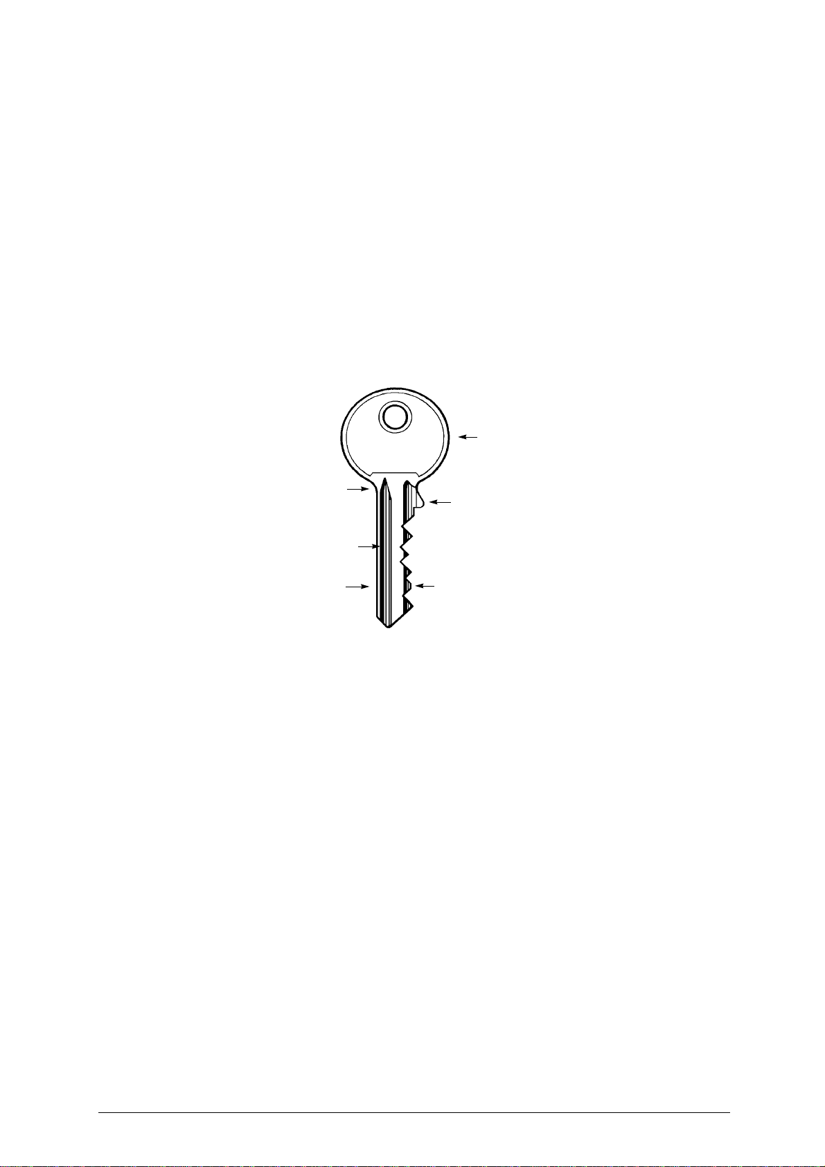
Technical terms
Common technical terms are used in this manual. To assist those with little experience of key cutting,
below is an illustration of the terms used for the different parts of keys:
Fig. 1 1) Head
2) Rim
3) Stop
4) Stem
5) Tip
6) Back
7) Cuts
2
1
5
7
3
6
4

RIGEL EU Operating manual - English
4
GENERAL INTRODUCTIONS
The RIGEL EU key-cutting machine has been designed according to the specifications of the Machine
Directives. From the design stage risks for the operator have been eliminated in all areas: transport,
key-cutting, regulation and maintenance.
Other risks have been eliminated by the use of protective devices for the operator.
The protective devices used are designed not to provoke further risks and, above all, they cannot be
ignored unless deliberately cut out. They do not hinder visibility of the work area.
A special adhesive label is attached to the machine warning the operator to use goggles during the cut-
ting operations, and this is strongly recommended in this manual.
The material used in the manufacture of this machine and the components employed during use of the
machine are not dangerous and their use complies with standards.
Use
The RIGEL EU must be installed and used in the way laid down by the manufacturer.
If the key-cutting machine is used differently or for purposes different from those described in this ma-
nual,thecustomerwillforego anyrights hemay haveoverILCO ORION. Furthermore,unforeseen dan-
ger to the operator or any third parties may arise from incorrect use of the machine.
Negligence in the use of the machine or failure on the part of the operator to observe the instructions
given in this manual are not covered by the guarantee and the manufacturer declines all responsibility
in such cases.
It is therefore indispensable to read the operating manual carefully in order to make the best use
of the RIGEL EU and benefit from its potential.
Further Risks
There are no further risks arising from the use of the machine.
Protection and safety precautions for the operator
The RIGEL EU key-cutting machine is built entirely to standards. The operations for which it has been
designed are easily carried out at no risk to the operator.
The adoption of general safety precautions (wearing protective goggles) and observation of the instruc-
tions provided by the manufacturer in this manual eliminate all human error, unless deliberate.
The RIGEL EU key-cutting machine is designed with features which make it completely safe in all its
parts.
•Power supply
The key-cutting machine is powered directly by electricity supplied through a safety device. The mains
plug must be earthed.
•Start-up
The machine is started up:
-by means of the START button on the safety device (standard with 230V key-cutting machines, on
request for other voltages).
-by means of the motor start-up switch on the left-hand side.
• Maintenance
The operations to regulate, service, repair and clean the machine have been devised in the simplest
and safest way possible. There is no danger of removable parts being re-placed wrongly or unsafelyo.
• Machine Identification
TheRIGEL EUkey-cutting machineis provided withan identification labelwhichshows theserial num-
ber (fig. 2).
Fig. 2
(*) see chap.9 WASTE DISPOSAL, page 21.

Operating manual - English RIGEL EU
5
1 TRANSPORT
The RIGEL EU key-cutting machine is easily transported and is not dangerous to handle. The packed
machine can be carried by one person.
1.1 Packing
The RIGEL EU is packed in a strong cardboard box, the dimensions of which are shown in fig. 3, suffi-
ciently robust to be used for storing the machine for long periods.
Inside the box the machine is enclosed in two expanded polymer shells. The shells and cardboard box
ensure safe transportation and protect the machine and all its parts.
Fig. 3
1.2 Transport
To avoid damaging the RIGEL EU it must always be transported in its packing case. This will prevent
sudden movements or rough handling from damaging the machine, persons or things.
1.3 Unpacking
To remove the machine from the packing box:
1) cut the straps with scissors and remove.
2) prise off the staples.
3) open the box without damaging it as it may be used again (e.g. removals, dispatch to the manufac-
turers for repairs or servicing).
4) check the contents of the box, which should comprise:
- 1 RIGEL EU key-cutting machine packed in a protective shell.
- 1 set of documents, including: operating manual, spare parts list and guarantee.
- 1 chippings tray.
- 1 tool tray.
- 1 connecting wire.
remove the key-cutting machine from the protective shell.
1.4 Handling the machine
When the RIGEL EU has been unpacked, place it directly on its workbench.
This operation can be carried out by one person, firmly holding the base, and no other part, to lift and
carry the machine.
1.5 Safety
Switch and cutter protection, mechanical stop of the carriage.
500 mm
600 mm
410 mm
Keep dry This side up
Handle with care

RIGEL EU Operating manual - English
6
2 WORKING PART
Fig. 4 A - carriage handle lever
B - carriage release lever
C - chippings tray
C1 - tool tray
D - carriage movement lever
E - clamps
F - clamp knobs
G - gauge knobs
H - gauge tabs
I - tracer point
J - tracer point locking grub screw
K-
centesimal ring
L- cutting tool
M - cutting tool cover
N - motor cover
O - motor start switch
P - brush
P1 - brush cover
Q - cover fixing Allen screw
R - clamp carriage
S-motor
T-belt
U - fuses
V - supply socket
N
S J
P
P1
T
M
L
H
F
E
R
AB
C
D
G
O
Q
I
K
V
U

Operating manual - English RIGEL EU
7
3 MACHINE DESCRIPTION
RIGEL EU is a professional cutting machine for flat keys used with cylinder, car locks and cruciform
keys. The main parts of the machine are described below:
Motor start-up switch
The motor start-up switch (O) is placed on the left-hand side of the RIGEL EU key-cutting machine.
ATTENTION: the illuminated switch is always lit to show that the key-cutting machine is live.
Motor and transmission unit
The motor has belt transmission. The transmission unit is placed on the left of the motor and activates
the brush (P) and cutting tool (L). These components are protected by three covers:
-brush cover (P1),
-cutting tool cover (M),
-motor cover (N).
Clamp carriage
Theclamp carriage(R) consistingof two clamps,is fittedto the horizontalmovementcarriage,controlled
by lever (D) and is provided with a handle (A) under which can be found the carriage release button (B).
The carriage movement by means of gears, allows high precision movements which greatly facilitate all
cutting operations.
The carriage is fully protected by a special panel designed to prevent the accumulation of dust and chip-
pings from the work process.
The machine is designed with a ramp along which chippings can fall into the special chippings tray (C),
placed under the carriage and easily removable for emptying and cleaning.
Cutting unit
The cutting unit contains the actual working parts of the RIGEL EU key-cutting machine, which operate
together to cut and finish keys "read" from the originals.
The working parts are described below:
•Brush
The brush (P) is used to eliminate burrs from the cuts and is made of non-abrasive material.
•Cutting Tool
The cutting tool (L) is the part of the RIGEL EU used for cutting key blanks. The cutting tool is in HSS
super rapid steel and is protected by a special cover (M) to ensure safe operation.
•Tracer point
The tracer point (I), used for reading the profile of the key to be copied, is housed on the left-hand side
of the machine base. A centesimal ring (K) ensures regulation of the depth.
•Clamps
The clamps (E) have four sides which rotate to allow the key to be perfectly secured on its back or in
profile (fig. 9 - pag. 15).
•Clamp knobs
The clamps are locked by two anatomical knobs (F)(fig. 4 - pag. 6) which ensure perfect grip on the keys
with only slight locking pressure.
•Calibration tabs
The clamps have two gange tabs (H)(fig. 8 -B) with which to adjust key alignment.

RIGEL EU Operating manual - English
8
3.1 Technical Data
Electricity supply:
230V-50Hz (110V-60Hz)
Maximum absorbed power:
230V: 1,9 Amp. 190 Watt - 110V: 3,5 Amp. 250 Watt
Cutting Tool:
HSS Super Rapid Steel
MOTOR: One-speed single phase:
230v - 50Hz: 1350 rpm (+/- 10%) / 110V - 60Hz: 1680 rpm (+/- 10%)
Movements:
by gear on rectified carriage.
Clamp:
rotating with four sides, high precision
Runs:
maximum length of cuts: 45 mm
Dimensions:
width: 375 mm depth: 440 mm height: 300 mm
Weight:
23 Kg.
Noise level :
sound pressure Lp(A) = 85.4 dB(A) (cutting steel keys)
Operating manual - English RIGEL EU
9
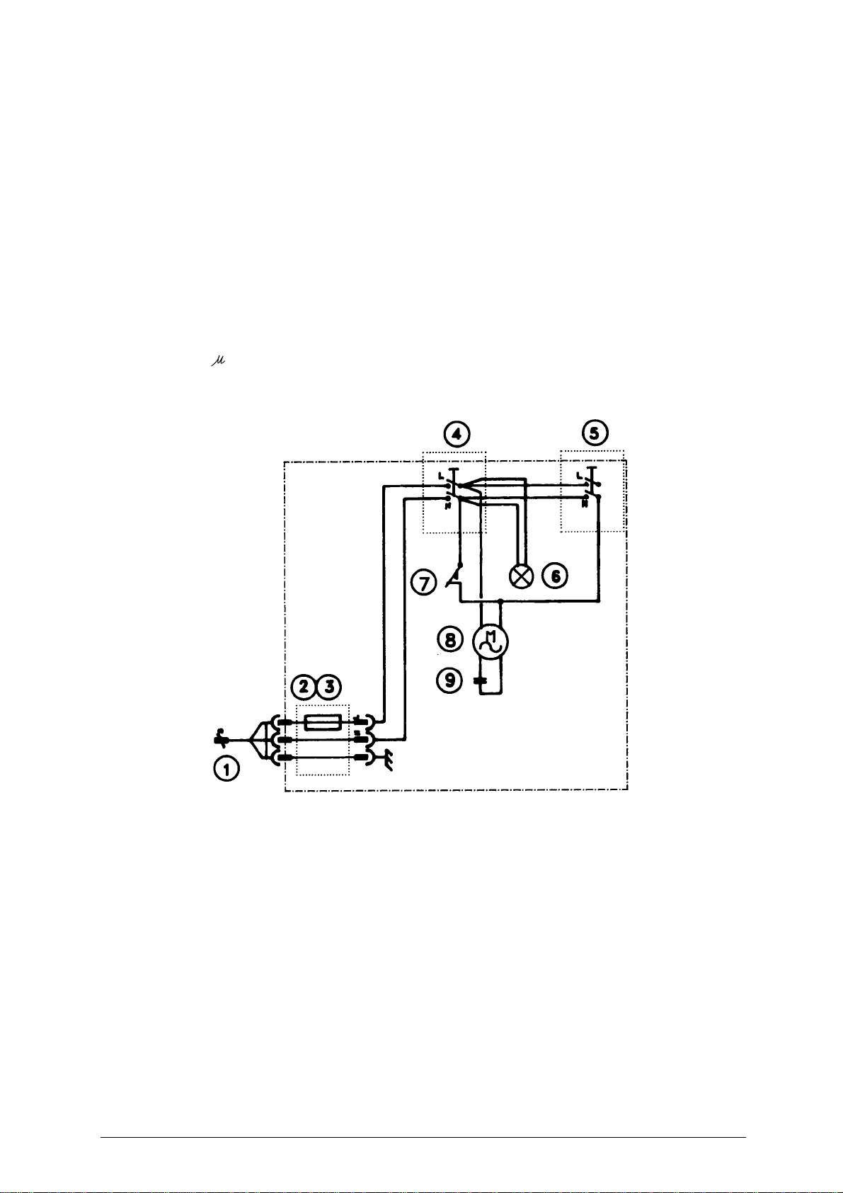
3.2 Electric circuit
The RIGEL EU key-cutting machine is provided with a single phase one-speed motor;
-230V: 1350 rpm, consumes approximately 0.18 Kw, absorption 1,5A;
110V: 1680 rpm, consumes approximately 0.18 Kw, absorption 3,5A.
The main parts of the electric circuit on the RIGEL EU are listed below:
1) Power supply cable
2) Plug with fuse holder
3) Delayed type glass 5A -230V / 8A -110V
4) Main switch
5) Brush button
6) Light bulb
7) Micro-switch
8) Motor: 230V a.c. 50Hz / 230V a.c. 60Hz / 110V a.c. 60Hz
9) 8 condenser
.
F

RIGEL EU Operating manual - English
10
4 ACCESSORIES PROVIDED
To ensure trouble-free working with the RIGEL EU, it is advisable to always have certain spare parts on
hand. It is advisable to always have a tool box containing: tools, cutting tools, brushes, belts and small
replacement parts.
RIGEL EU is supplied with a full range of accessories.
The accessories provided by ILCO ORION are all that is necessary to carry out the operations for which
the machine is designed.
cod. D401224ZZ
STEEL PIN Ø 1,20
2 pz
cod. D401225ZZ
STEEL PIN Ø 1,70
2 pz
1
2
3
4
5
cod. DMS200340J
13/17/19 mm
SPANNER
cod. DMS200042J
CUTTING TOOL
UNCLAMPING PIN
cod. DMS200080J
ADJUSTMENT PLATE
2 pz
cod. D300225ZZ
5 mm ALLEN KEY
6

Operating manual - English RIGEL EU
11
5 MACHINE INSTALLATION AND PREPARATION
The RIGEL EU key-cutting machine can be installed by the purchaser and does not require any special
skills.
However, some checks and preparation for use need to be carried out by the operator.
5.1 Checking for damage
The RIGEL EU key-cutting machine is solid and compact and will not normally damage if transport,
unpacking and installation have all been carried out according to the instructions in this manual.
However, it is always advisable to check that the machine has not suffered any damage.
5.2 Environmental conditions
To ensure that the best use is made of the RIGEL EU key-cutting machine, certain parameters must be
borne in mind:
-damp, badly ventilated sites should be avoided.
-The ideal conditions for the machine are:
- temperature: da 0 a 40°C
relative humidity: 60% circa
5.3 Positioning
Place the key-cutting machine on a horizontal surface, solid enough to take the weight (23 Kg).
To facilitate operation and maintenance, install the machine with a space of at least 200mm on all sides
(fig. 5).
Ensure that the machine stands perfectly balanced on the four feet. Vibration is avoided when the ma-
chine is properly set on the horizontal plane
ATTENTION: Ensure that the machine voltage is the same as that of the mains, which must be properly
earthed and provided with a differential switch.
Fig. 5
200mm
200mm
200mm
RIGEL EU Operating manual - English
12
5.4 Description of the work station
The key-cutting machine needs only one operator, who has the following controls at his/her disposal:
-Motorstartswitch (O)(fig.4 -pag. 6),placed onthe left-handsideof themachine; illuminatedto show
that the machine is live.
-Carriage movement lever (D)(fig. 4 - pag. 6).
-Carriage handle lever (A)(fig. 4 - pag. 6).
-Carriage release lever (B)(fig. 4 - pag. 6).
-Gauge knob (G)(fig. 4 - pag. 6).
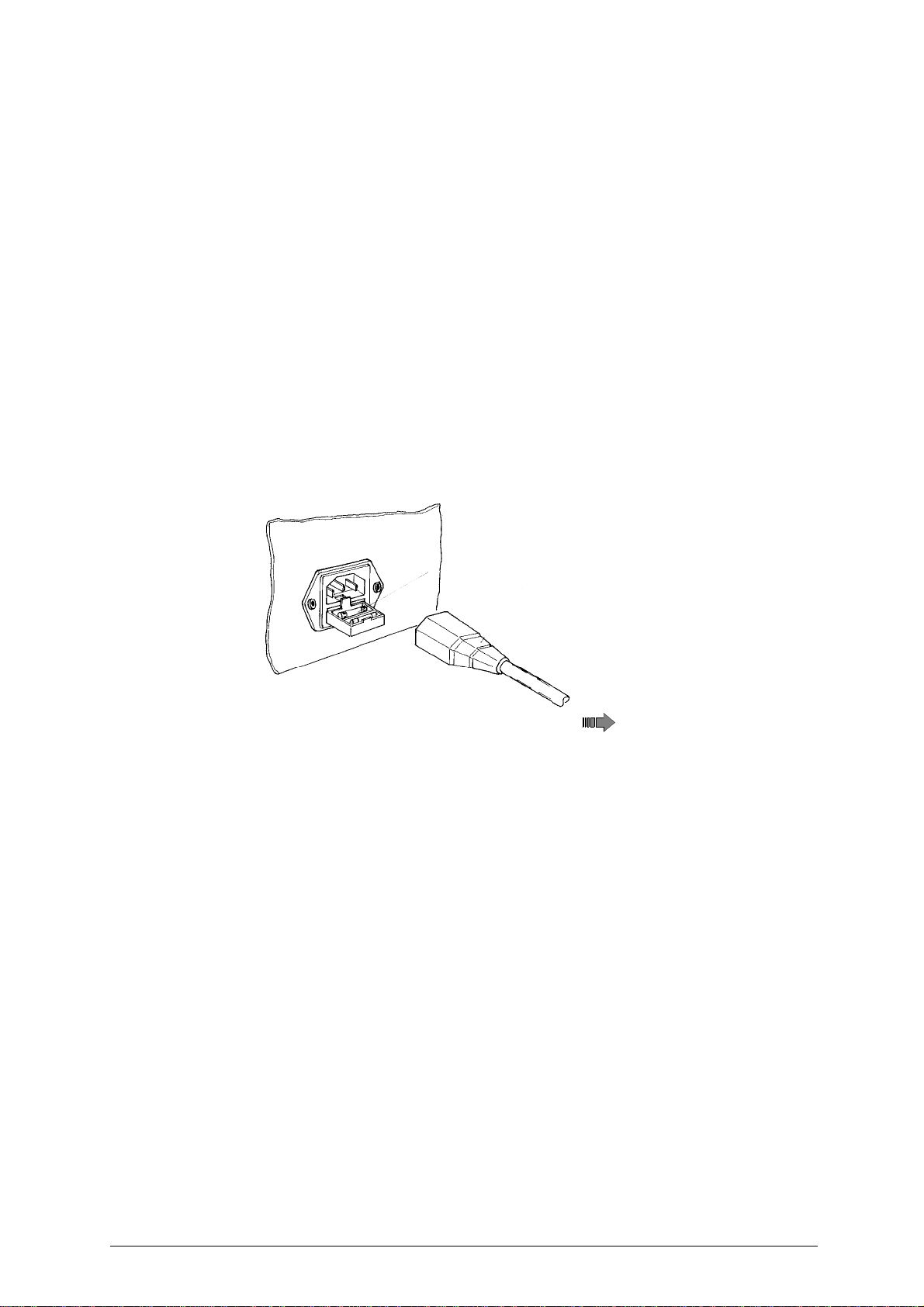
5.5 Separate parts
The separately packed parts must beinstalled on the RIGEL EU key-cutting machine by the purchaser,
as follows:
Connection wire
Connect the key-cutting machine and the power cable, then connect the free end of the power cable to
the electricity supply (fig. 6).
Fig. 6
Removing the blocks
Remove the plastic block between the carriage and the machine body.
5.6 Connection to the mains
For the safety of the operator and the machine it is important to ensure that the machine is connected
to the proper mains voltage by means of an earthed differential switch.
electricity
supply
Operating manual - English RIGEL EU
13
6 REGULATION AND USE OF THE MACHINE
6.1 Checking and setting
The cutting tool on the RIGEL EU is the part used to cut the key blanks and should be periodically che-
cked and replaced, if necessary.
Every time the cutting tool is changed, and during periodical operational tests, check calibration.
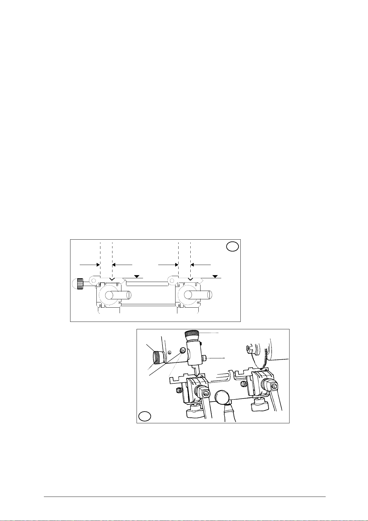
6.2 Calibration
The RIGEL EU key-cuttung machine requires two types of calibration: axis and depth.
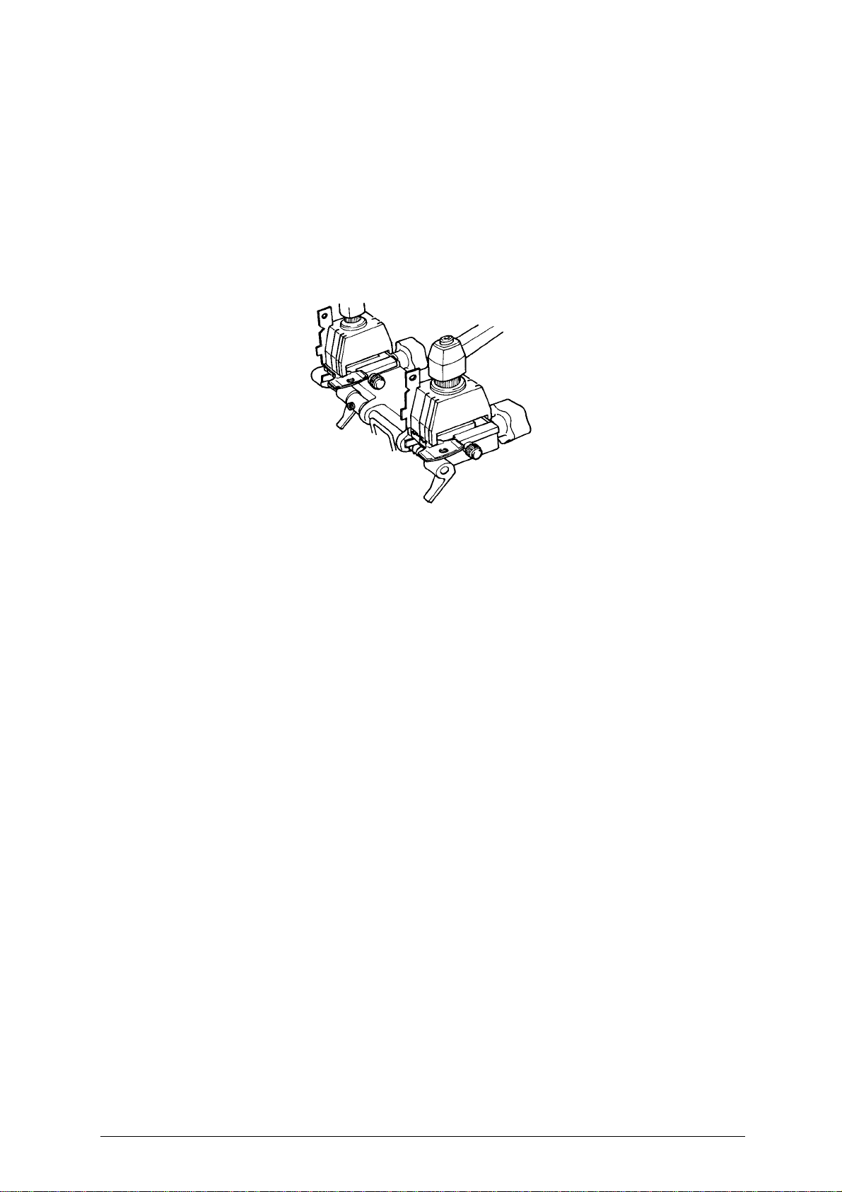
Axis calibration:
Axis calibration is regulation of the space between the stop and the cuts (fig. 7-A).
The axis setting for the RIGEL EU is fixed and is established on assembly in our workshops.
ATTENTION: Before carryng out this operation, adjust the cutting depth.
1) Remember to disconnect the machine from the mains.
2) Make sure the back of the gauges is lined up perfectly with the surface of the clamp and adjust the
interaxial distance using the positioners H.
3) Move the clamp carriage so that the cutter and the tracer fit in the V shaped slits in the gauges.(fig.
7-B).
4) The cutting interval of the machine is correct when the cutter and the tracer fit perfectly into the V
shaped slits in the gauges. Otherwise proceed as follows :
- Loosen the screw J1.
- Turn the knob K1 until the above mentioned occurs.
- Fasten the srew K1.
Fig. 7
B
K
J
K1
J1
A

RIGEL EU Operating manual - English
14
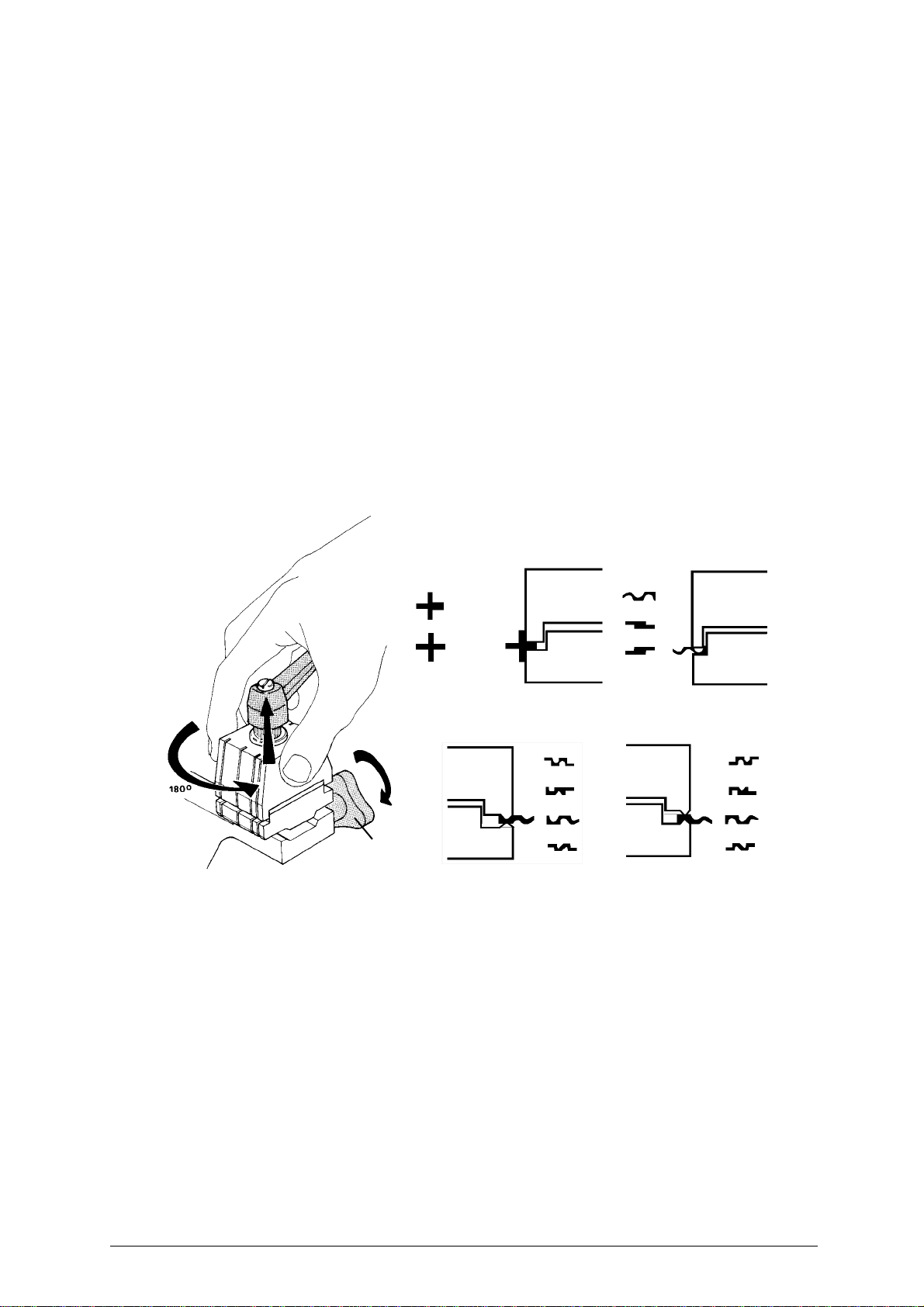
Depth calibration:
Depth calibration is regulation of the cutting depth .
Proceed as follows
:
1) Remember to disconnect the machine from the mains.
2) Insert the supplied gauges horizontally in the clamp housing (fig. 8-B).
3) Make sure the back of the gauges is lined up perfectly with surface of the clamp. (fig. 8-B).
4) Move the carriage towards the cutter and the tracer until the tracer rests on the gauge.
5) Turn the cutter manually.
6) The cutting depth of the machine is correct when the cutter skims the gauge freely. Otherwise pro-
ceed as follows:
a) Loosen the screw (J).
b) Turn the knob (K) clockwise or anticlockwise until the above mentioned occurs.
c) Fasten the screw (J).
.
Fig. 8(A-B)
K
J
HH
B
A
B
Operating manual - English RIGEL EU
15
7KEY CUTTING
ATTENTION: For complete safety during the cutting operations, take the following precautions:
- Always work with dry hands.
- Check that the machine is properly earthed.
- Wear protective goggles even if the machine has a protective shield over the cutting tool.
- Start the motor (switch P) only after completing the operations on the carriage (securing the
keys, etc.).
-Keep hands away from the cutting tool in motion.
7.1 Key cutting system
1) Turn the clamps to find the appropriate side for securing the key (fig. 9-B)
2) Loosen the knobs (F1) by a couple of turns (fig. 9-A).
3) Raise the lower part of the clamps and turn to the required position:
- Side A of the clamp: for keys to be fitted on their backs (fig. 9-B);
- Side B of the clamp: for keys to be cut on both sides and locked on the groove (fig. 9-B).
Securing the keys in the jaws
1) Position the original key (left-hand jaw) and key blank (right-hand jaw), ensuring that:
a) the keys are positioned and secured as described in chap. 7.1, page 15;
b) the key stop is resting against the calibration tabs (H)(fig. 4 - pag. 6);
2) secure the keys by closing the clamps with the knobs (F)(fig. 4 - pag. 6).
Fig. 9
Key cutting
When the RIGEL EU key-cutting machine has been turned on by meansof switch (O) it is ready for cut-
ting:
1) Take the carriage up to the tracer point and cutting tool by releasing the push lever (B).(fig. 8)(A)
2) To copy the key, move the carriage sideways from right to left by means of the lever (D).(fig. 4, pag.
6)
3) Turn off the machine with switch (O)(fig. 4, pag. 6) before removing the duplicated key.
4) Remove the keys from the clamps.
5) Turn on the machine with switch (O) and smooth off the key edges by means of the brush (P)(fig. 4
- pag. 6).
Using the accessories
The accessories provided with the RIGEL EU to assist key-cutting are:
-Pins
-Bars
B
A
F1

RIGEL EU Operating manual - English
16
Using the pins
The pins must be inserted between the bottom of the jaw and the back of the key for keys with narrow
stems, and their purpose is to ensure that the key protrudes sufficiently to be cut properly (fig. 10, fig.
10-C).
For keys with narrow, thin stems, two pins must be used (fig. 10-B), the second one to give a secure
grip on the key. If the key thickness is too fine to guarantee a good grip in the clamps, a pin must be
used (fig. 10-A).
ATTENTION: The pins provided have two different diameters: 1,20 mm and 1,70 mm. It is essential to use pins
with the same diameters for locking both the original and the key blank.
Fig. 10
Using the bars
The bars provided are used for cutting pin keys and as a tip rest for locking keys with no stop (fig. 12).
Cutting pin keys using bars
All types of pin keys (90°) can be cut with the RIGEL EU clamps and the aid of the bars.
Positioning pin keys:
1) Leave the gauges in the idle position.
2) Insert the bars with neck into the slot in the clamps.
3) Butt the key stop against the bars (fig. 11).
4) Secure the keys in the clamps.
5) Remove the bars from the clamp grooves to prevent it being touched by the tracer point or cutting
tool.
6) Cut the first side.
7) Repeat the operation, turning the keys in the same direction for the other positions
Fig. 11
AB C
Operating manual - English RIGEL EU
17
Tip stop with a bar
The bars can be used with keys which have no stop (fig. 12). Proceed as follows:
1) Leave the gauges in the idle position.
2) Insert the bars into the slot in the clamps.
3) Rest the tip of the key against the bar.
4) Secure the key and remove the bar.
Fig. 12
RIGEL EU Operating manual - English
18
8 MAINTENANCE
Although the RIGEL EU key-cutting machine does not require special maintenance, it is advisable to
check and, if necessary, replace the parts subject to wear, such as: the belt, cutting tool, brush, tracer
point. Replacement is simple and can be carried out by the operator.
CLEANING
Keep the carriage and clamps free of chippings from the cutting operations by cleaning with a dry brush.
ATTENTION: do not use compressed air!
Before starting any type of maintenance (checks or replacements), read the instructions below:
-never carry out maintenance or servicing with the machine switched on.
-always remove the mains plug.
-follow all the instructions in the manual to the letter.
-use original spare parts.
-always check that any screws or nuts removed when replacing a piece are properly tightened.
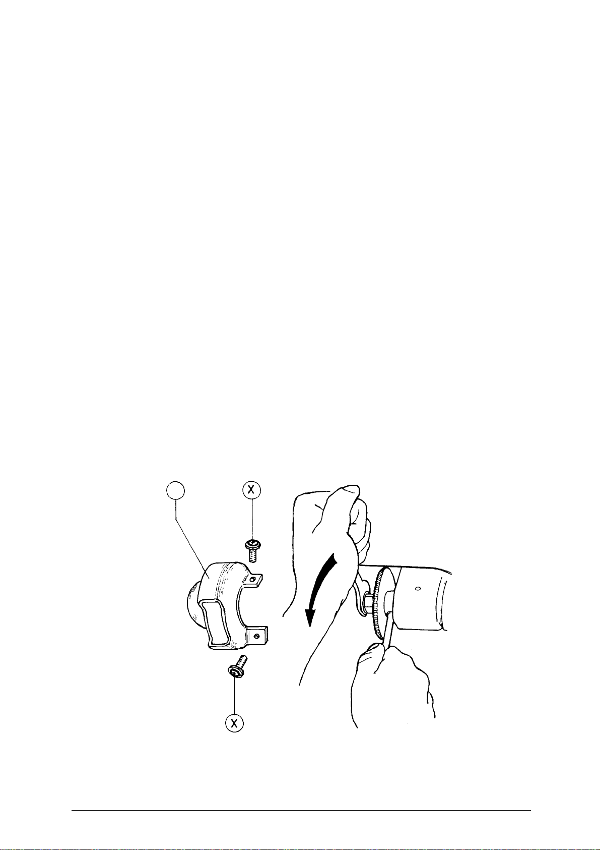
8.1 Replacing the cutting tool
In order to substitute the cutting tool you don’t need to remove the cutting tool cover.
To replace a worn cutting tool, proceed as follows:
ATTENTION: Remove the mains plug.
1) Remove the cover.
1) Slot the locking rod (standard) into the hole of the cutting tool shaft (fig. 13).
2) Use the spanner provided to loosen the cutting tool locking nut.
3) With the spanner provided loosen the cutting tool locking nut.
ATTENTION: The thread is left-handed.
4) Remove the worn cutting tool.
5) Carefully clean the new cutting tool and its seat.
6) Install the new cutting tool and tighten the nut.
ATTENTION: The tool rotates clockwise.
7) Remove the locking pin
8) Replace the cover.
Fig. 13
M
Table of contents
Other Ilco Orion Cutter manuals


