Ilco Orion NOVA 2000 User manual
®
D430548XA
vers.
2.0
Operating manual
NOVA 2000

NOVA 2000 Operating manual - English
0
(c) 2001 Silca - Vittorio Veneto
This manual has been drawn up by ILCO ORION
rights reserved. No part of this publication may be reproduced or used in any form or by any means (photocopying, microfilm
or other) without the permission of ILCO ORION.
Edition: june 2006
Printed in Vittorio Veneto
by ILCO ORION
via Podgora, 20 (Z.I.)
31029 VITTORIO VENETO (TV) - Italy

INDEX
GUIDE TO THE MANUAL ...................................................................................3
GENERAL INTRODUCTION ...............................................................................4
1 TRANSPORT ...................................................................................................5
1.1 Packing .................................................................................................5
1.2 Transport ..............................................................................................5
1.3 Unpacking .............................................................................................5
1.4 Handling the machine ...........................................................................6
1.5 Safety ....................................................................................................6
2 MACHINE DESCRIPTION ...............................................................................7
3 Working parts .................................................................................................9
3.1 Technical data ....................................................................................10
3.2 Graphics .............................................................................................10
3.3 Electrical circuit....................................................................................11
4 ACCESSORIES PROVIDED .........................................................................12
5 MACHINE INSTALLATION and PREPARATION ........................................13
5.1 Checking for damage ..........................................................................13
5.2 Environmental conditions ....................................................................13
5.3 Positioning ..........................................................................................13
5.4 Description of work station ..................................................................13
6 MACHINE REGULATION AND UTILIZATION .............................................14
6.1 Fitting and regulating the tools ............................................................14
6.2 Setting .................................................................................................14
7 CUTTING OPERATIONS ..............................................................................15
7.1 Key cutting ..........................................................................................15
7.2 Cutting keys with key stops ................................................................15
7.3 Cutting keys without key stops ...........................................................15
7.4 Inserting the spring system .................................................................16
7.5 Cutting Laser (Sidewinder) type keys .................................................16
7.6 Cutting narrow-stemmed Laser (Sidewinder) type keys .....................16
7.7 Cutting keys for FICHET .....................................................................16
8 MAINTENANCE .............................................................................................17
8.1 Replacing the belt and adjusting tension ............................................17
8.2 Replacing the light bulb ......................................................................18
8.3 Checking and replacing the fuses .......................................................18
9 DISPOSING OF MACHINE ...........................................................................19
10 AFTER-SALES SERVICE .............................................................................20
10.1 How to request service .......................................................................20

Operating manual - English NOVA 2000
3
GUIDE TO THE MANUAL
This manual has been produced to serve as a guide for users of the NOVA 2000 key-cutting machine.
Read it carefully; it is essential if you wish to operate your machine safely and efficiently.
Consultation
The contents of the manual are divided into sections relating to:
- Transport and handling ...............................................................................................Ch. 1
- Description of machine and safety devices ................................................................Ch. 2-3-4
- Proper use of machine ...............................................................................................Ch. 5-6-7
- Maintenance ...............................................................................................................Ch. 8-9-10
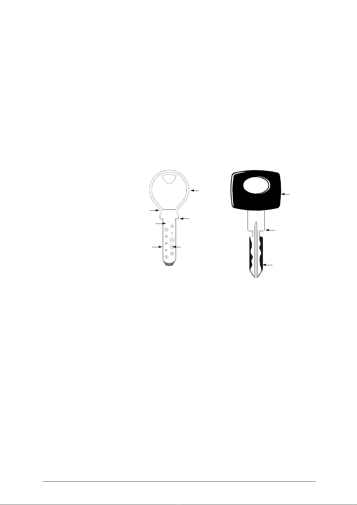
Technical terms
Common technical terms are used in this manual. To assist those with little experience of key cutting,
below is an illustration of the terms used for the different parts of keys.
Fig. 1
1) Head
2) Rim
3) Stop
4) Stem
5) Tip
6) Back
7) Cuts
2
1
5
7
3
4
6
1
5
7
3
DIMPLE KEY LASER (SIDEWINDER) TYPE KEY
keys with holes of different
dimensions, depths, positions
and shapes.
LASER is the name given to the
special sidewinder milled keys.

NOVA 2000 Operating manual - English
4
GENERAL INTRODUCTION
The NOVA 2000 key-cutting machine has been designed according to the specifications of the Machine
Directives.Fromthedesignstagerisksfor the operator have been eliminatedinallareas: transport,key-
cutting, regulation and maintenance.
Other risks have been eliminated by the use of protective devices for the operator.
The protective devices used are designed not to provoke further risks and, above all, they cannot be
ignored unless deliberately cut out. They do not hinder visibility of the work area.
A special adhesive label is attached to the machine warning the operator to use goggles during the
cutting operations, and this is strongly recommended in this manual.
The material used in the manufacture of this machine and the components employed during use of the
machine are not dangerous and their use complies with standards.
Use
The NOVA 2000 must be installed and used in the way laid down by the manufacturer.
If the key-cutting machine is used differently or for purposes different from those described in this
manual, the customer will forego any rights he may have over Ilco-Orion. Furthermore, unforeseen
danger to the operator or any third parties may arise from incorrect use of the machine.
Negligence in the use of the machine or failure on the part of the operator to observe the instructions
given in this manual are not covered by the guarantee and the manufacturer declines all responsibility
in such cases.
It is therefore indispensable to read the operating manual carefully in order to make the best use
of the NOVA 2000 and benefit from its potential.
Further Risks
There are no further risks arising from the use of the machine.
Protection and safety precautions for the operator
The NOVA 2000 key-cutting machine is built entirely to standards. The operations for which it has been
designed are easily carried out at no risk to the operator.
The adoption of general safety precautions (wearing protective goggles) and observation of the
instructions provided by the manufacturer in this manual eliminate all human error, unless deliberate.
The NOVA 2000 key-cutting machine is designed with features which make it completely safe in all its
parts.
• Power supply
The key-cutting machine is powered directly by electricity supplied through a safety device
(standard
with 230V key-cutting machines, on request for other voltages).
• Start-up
The machine is started up
:
- by means of the main switch on the safety device (standard with 230V key-cutting machines);
- by means of the master switch.
•Operation
The machine is started up by means of a motor switch.
• Illumination
The work area is illuminated by a lamp which operates when the machine is switched on with the master
switch.
• Maintenance
The operations to regulate, service, repair and clean the machine have been devised in the simplest
and safest way possible. There is no danger of removable parts being re-placed wrongly or unsafely.
• Machine identification
The NOVA 2000 key-cutting machine is provided with an identification label which shows the serial
number (fig. 2).
Fig. 2
(*) see chap. 9 DISPOSING OF MACHINE, page 19.
Operating manual - English NOVA 2000
5
1 TRANSPORT
The NOVA 2000 key-cutting machine is easily transported and is not dangerous to handle.
The packed machine can be carried by two persons.
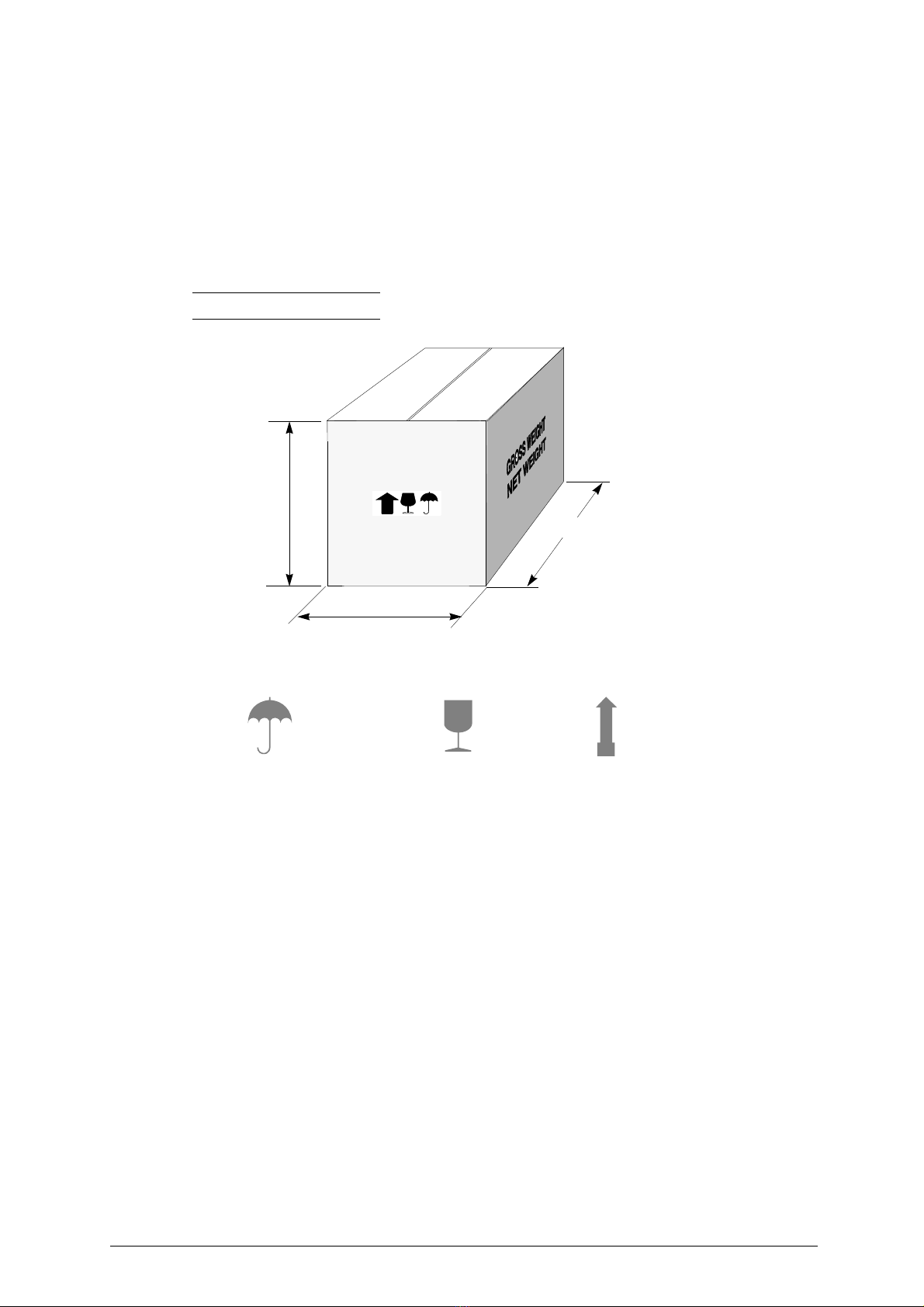
1.1 Packing
The packing used for the NOVA 2000 guarantees that the machine will travel safely without danger of
damage to it or its components.
The packing comprises two shells, lower and upper in expanded plastic in the machine is wrapped.
A strong outer cardboard box, the measurements of which can be seen in fig.3 and the plastic wrapping
protect the machine even over a long period of storage.
Note: keep the packing and use it every time the machine must be transported.
Fig. 3
1.2 Transport
Symbols are printed on the outside of the cardboard box to give instructions and warnings for
transportation.
Use of the packing box whenever the machine is transported will avoid knocks or bumps which could
cause damage.
1.3 Unpacking
To remove the machine from the packing box:
1) cut the straps with scissors and remove.
2) open the box without damaging it as it may be used again (e.g. removals, dispatch to the
manufacturers for repairs or servicing).
3) check the contents of the box, which should comprise:
1 NOVA 2000 key-cutting machine packed in a protective shell.
1 set of documents, including: operating manual, spare parts list and guarantee.
1 accessory container.
1 connecting wire.
1 safety device (supplied with the 230V machines);
4) remove the key-cutting machine from the protective shell.
500 mm
600 mm
410 mm
Keep dry This side up
Handle with care

NOVA 2000 Operating manual - English
6
1.4 Handling the machine
When the NOVA 2000 has been unpacked, place it directly on its workbench.
This operation can be carried out by one person.
ATTENTION: holding the base, and no other part, to lift and carry the machine.
1.5 Safety
• Protective shield
A special transparent plastic shield prevents chippings from flying into the air.
• Safety device
The device is connected to a power plug with a differential switch, power the key-cutting machine by
pressing the switch (X1).
The warning light (X2) illuminates to indicate voltage in the plug (X3).
ATTENTION: switch (X1) is electromagnetic, in the event of a power failure it goes out automatically. When
electricity is restored it must be reset manually to power the machine again bymeans of theplug
(X3).

Operating manual - English NOVA 2000
7
2 MACHINE DESCRIPTION
The NOVA 2000 is an excellent quality, high precision key-cutting machine. It features great versatility
in cutting keys of different types without the need to replace the clamp or apply fixed adapters.
NOVA 2000 cuts the following types of keys:
• dimple keys
(with flat cuts)
• Laser (sidewinder) type keys
• keys for Fichet
Fig. 4
dimple keys
keys for Fichet
with Optional
Laser narrow-stemmed
(sidewinder) type keys
Laser (sidewinder) type keys
+
++
+

NOVA 2000 Operating manual - English
8
High precision work is guarantee by the combination of the functional features on the NOVA 2000 and
all its components, such as:
• MOVEMENTS
The three axes move on ball guides which provide smooth running and easy sliding without play.
• TRACER POINT SPRING SYSTEM
This system guides and facilitates self-centering of the cuts on dimple keys.
• PROTECTIVE SHIELD
A special transparent plastic shield prevents chippings from flying into the air.
•LAMP
Placed directly on the machine, it illuminates the work area.
• CENTESIMAL MICROMETRIC RING NUT
Ensures perfect depth alignment of the tools and makes it possible to adjust for defects on worn keys
with minute, controllable depth variations (+/- 0,02 mm).
• LEVERS AND KNOBS
Each lever and knob has been designed with dimensions, materials and positions which render grip and
movement extremely simple.
Materials and finish have been chosen according to the use of each part, especially:
• lever (I) for vertical carriage (Z axis)
• lever (C) X-Y axes
The lever which guides movement along the X-Y axes is ergonomic and makes precise, sensitive
movements.
Fig. 5

Operating manual - English NOVA 2000
9
3WORKING PARTS
Fig. 6
A - clamp carriage (X-Y axes)
B - left-hand jaw
B1- right-hand jaw
C - clamp carriage lever (X-Y axes)
E - left-hand jaw knob
E1- right-hand jaw knob
G - protective shield
H - clamp carriage locking knobs
H1- clamp group locking knob
I - vertical carriage lever (Z axis)
L - sleeve (cutting tool and tracer point holder)
N - micrometric ring nut for tracer point adjusting
O - regulating knob spring system
P - master switch
Q - motor start switch
R - “Z” axis locking knob
X - safety device (standard with 230V key-cutting machines)
X1- main switch
X2- warning light
X3- plug
I
G
L
E1
Q
B1
O
H
BE
C
L
N
A
P
R
XX1
X3
H1
X2

NOVA 2000 Operating manual - English
10
3.1 Technical data
Electricity supply:
230V-50Hz (110V-60Hz)
Maximum absorbed power:
230V: 1 Amp. 210 Watt
Motor:
One-speed single phase
Cutting tool:
Super rapid steel HSS
Movements:
50Hz: 6000 rpm (+/- 10%) - 60Hz: 7000 rpm (+/- 10%)
Movements:
on 3 axes: vertical axis on bars, longitudinal and transversal axes on bars and bushings
Clamp:
universal interchangeable
Runs:
X axis (lower): 40 mm Y axis (upper): 50 mm Z axis (vertical): 30 mm
Dimensions:
width: 250 mm depth: 370 mm height: 370 mm
Weight:
Kg. 24
Sound pressure:
sound pressure Lp(A)
- steel: max. 97,4 dB(A)
- brass: max 97,8 db(A)
3.2 Graphics
Fig. 7
THE USE OF PROTECTIVE GOGGLES
IS COMPULSORY

Operating manual - English NOVA 2000
11
3.3 Electrical circuit
The main parts of the electrical and electronic circuit on the NOVA 2000 are listed below:
1 - Safety device inlet
2-
Safety main switch
3-
Warning light
4-
Wiring clip
5 - Machine plug
6 - Fuse rapid 5x20 3,15A - 250V
7 - Master switch
8 - Lamp 25W 230V
9 - Motor start switch
10- Electric motor with collector 200W - 220V - 50Hz
Fig. 8
Safety device
3
brown
blue
yellow-green
brown
blue
OUT
IN
4
1
2
6
6
58
10
9
7
Filter
Motor

NOVA 2000 Operating manual - English
12
4 ACCESSORIES PROVIDED
A set of accessories is supplied for use with the machine or for servicing (tools, Allen keys and
adapters).
The accessories provided are:
code DMK260047
TRACER POINT
for Laser (sidewinder) keys
code D300223ZZ
3 mm ALLEN KEY
code DR94352J
STEEL TIP STOP BAR
2 pcs.
1
2
3
4
5
6
code DMK260043
CUTTING TOOL
for dimple keys
code DMK260044
TRACER POINT
for dimple keys
code DMK260048
F22 CUTTING
for Laser (sidewinder) keys

Operating manual - English NOVA 2000
13
5 MACHINE INSTALLATION AND PREPARATION
The key-cutting machine can be installed by the purchaser and does not require any special skills.
The machine is supplied ready for use and does not need to be set up, except when changing to
different tools. However, some checks and preparation for use need to be carried out by the operator.
5.1 Checking for damage
The NOVA 2000 key-cutting machine is solid and compact and will not normally damage if transport,
unpacking and installation have all been carried out according to the instructions in this manual.
However, it is always advisable to check that the machine has not suffered any damage.
5.2 Environmental conditions
To ensure that the best use is made of the NOVA 2000 key-cutting machine, certain parameters must
be borne in mind:
- damp, badly ventilated sites should be avoided.
- the ideal conditions for the machine are:
temperature: between 0 and 40°C; relative humidity: approx 60%
5.3 Positioning
Place the key-cutting machine on a horizontal surface, solid enough to take the weight.
For comfort when using the working parts of the machine, the workbench should be at the same height
as the operator’s hips.
Iit is important to leave clearance of at least 30 cm behind the machine and on each side to ensure
proper ventilation.
Fig. 9
ATTENTION: ensure that the machine voltage is the same as that of the mains, which must be properly
earthed and provided with a differential switch.
5.4 Description of work station
The key-cutting machine needs only one operator, who has the following controls at his/her disposal:
• safety device (X) (standard with 230V key-cutting machines).
• master switch (P).
• motor start switch (Q).
• levers:
lever (C) to move the clamp carriage
lever (I) to move the vertical carriage
Note: the letters in brackets refer to fig. 6 on page 9.
300mm
300mm
300mm

NOVA 2000 Operating manual - English
14
6 MACHINE REGULATION AND UTILIZATION
Before carrying out cutting operations is necessary proceed with regulation about:
• fitting the tools and setting
• inserting the spring system (for dimple keys) (ch.7.4, page 16)
6.1 Fitting and regulating the tools
ATTENTION: switch on the machine with the master switch.
to remove the tracer point and cutting tool from the sleeves:
1) place the tracer point all the way into the left-hand sleeve and secure by tightening the grub screw
(M) (fig. 10).
2) place the cutting tool all the way into the right-hand sleeve and secure by tightening the grub screw
(M1).
Releasing the tools
Unscrew the grub screw (M) and (M1) to remove the tracer point and cutting tool from the sleeves.
Fig. 10
6.2 Setting
Set up the tools, place two keys into the clamps and proceed as follows (see fig. 6 on page 9):
1) turn the micrometric ring nut (N) anti-clockwise.
2) lower the vertical carriage by means of the lever (I) and rest the tracer point lightly on the relative
key.
3) turn the micrometric ring nut (N) clockwise until the cutting tool touch the relative key.
4) lock ring nut (O) and the knob.
M1
M

Operating manual - English NOVA 2000
15
7 CUTTING OPERATIONS
For complete safety during the cutting operations, take the following precautions:
• Always work with dry hands.
• Check that the machine is properly earthed.
• Wear protective goggles even if the machine is provided with a safety shield over the cutting
tool.
• Before starting the motor (switch Q), carry out the following operations:
a) place the keys into the clamps.
b) install the tools and gauge them.
• Keep hands away from the cutting tool in motion.
7.1 Key cutting
1) Connect the machine using the switch (P).
2) press the switch (Q) to turn on the cutter.
3) using the lever (C) move the clamp group according to the cuts that have to be carried out.
4) using the lever (I) lower the cutter/tracer group so that the tracer enters every groove of slit in the
sample key. Press the lever (I) with sufficient force to make sure the cutter removes all the
necessary parts of material from the key being cut.
5) repeat the operation for each groove.
6) after having carried out all the cuts, turn the machine off using the switch (Q) and remove the keys
from the clamps.
7.2 Cutting keys with key stops
1) Block the sample key in theleft hand clamp of the machine making sure that the key stop is pressed
against the clamp.
2) block the key to be cut in the right hand clamp of the machine making sure that the key stop is
pressed against the clamp.
3) adjust the machine according to paragraph 6.2. The machine must be adjusted every time one of
the utensils is changed.
4) cut the key according to paragraph 7.1.
7.3 Cutting keys without key stops
1) Insert the metal pin into the slit in the left hand clamp using the first or second groove according to
the key to be cut.
2) block the sample key in the left hand clamp of the machine making sure that the key tip is pressed
against the stop pin.
3) block the key to be cut in the right hand clamp of the machine making sure that the key tip is pressed
against the stop pin.
4) adjust the machine according to paragraph 6.2. The machine must be adjusted every time one of
the utensils is changed.
5) cut the key according to paragraph 7.1.
Cutting the back
If cuts are to be made on the back, place the key in a vertical position.
Fig. 11

NOVA 2000 Operating manual - English
16
7.4 Inserting the spring system
The NOVA 2000 key-cutting machine is equipped with a spring mechanism which allows precise
duplication of dimple keys. Using this system, it is possible to position the tracer into the groove of the
sample first and then proceed with cutting the key. The spring system is to be used only for dimple keys
(fig. 1) and is activated by rotating the ring nut (O).
Note: for laser type keys (fig. 1) deactivate this function.
7.5 Cutting Laser (Sidewinder) type keys
Before activating the start switch (Q) lower lever (I) lose to the keys and regulate the spring system for
laser (sidewinder) key with knob (O).
- start the cutting operation by activating switch (Q).
- lower the spindle and rest the tracer point on a cut part of the original key, cut the key and stop at
the beginning of the cut.
• secure the spindle at this height by means of knob (R).
• carry out the cuts using only the left-hand lever (C).
Fig. 12
7.6 Cutting narrow-stemmed Laser (Sidewinder) type keys
The clamp can also be used to cut narrow-stemmed Laser (sidewinder) keys by simply fitting the
adapter provided (optional). Proceed as follows:
1) open the clamps by loosening knobs (E) and (E1).
2) place the stop bar into the groove.
3) insert the key so that it butts against the bar.
4) secure the adapter and key by tightening knob (E).
5) remove the bar and repeat the same operations on the right-hand jaw.
Cutting:
1) before activating the start switch (Q) lower lever (I) close to the keys.
2) start the cutting operation by activating switch (Q).
3) lower the spindle, cut the key and stop at the beginning of the cut (ch. 7.5).
• secure the spindle at this height.
• carry out the cuts using only lever (C).
7.7 Cutting keys for FICHET
The clamp can also be used to cut keys for FICHET (H profile). Proceed as follows:
- open the clamps slightly by loosening knobs (E) and (E1) (fig. 6, page 9).
- place the keys with the stop up against the clamp.
- secure the keys by tightening knobs (E) and (E1).
Cutting:
turn on switch (Q), lower the collet assembly and position on the beginning of the cut.
• secure the spindle at this height.
• carry out the cuts using only lever (C).
Fig. 13
®
®

Operating manual - English NOVA 2000
17
8 MAINTENANCE
Although the NOVA 2000 key-cutting machine does not require special maintenance, it is advisable to
check and, if necessary, replace the parts subject to wear, such us: the (ch. 8.1) and the lamp (ch. 8.2).
Replacement is simple and can be carried out by the operator.
CLEANING
: keep the carriage and clamps free of chippings from the cutting operations by cleaning with
a dry brush.
ATTENTION: DO NOT USE COMPRESSED AIR!
Before starting any type of maintenance (checks or replacements), read the instructions below:
• never carry out maintenance or servicing with the machine switched on.
• always remove the mains plug.
• follow all the instructions in the manual to the letter.
• use original spare parts.
8.1 Replacing the belt and adjusting tension
If the upper part of the machine vibrates, check the tension on the belt, as described below:
1) turn off the master switch and remove the mains plug.
2) loosen the four screws (Y1), knob (R) (fig. 6, page 9) and remove the upper casing (Y).
3) loosen (but do not remove) the four socket head screws (Y2) securing the motor.
4)
a) tension:
- increase belt tension by pushing the motor towards the back of the machine.
b) replacement:
- loosen the belt by pushing the motor slightly towards the tracer point and cutting tool.
- remove the belt and replace.
- tighten the tension by pushing the motor towards the back of the machine.
5) secure the motor by tightening the four socket head screws (Y2).
6) replace the upper casing (Y), secure with the four screws (Y1) and replace knob (R).
Fig. 14
Y
Y1
belt
Y2
NOVA 2000 Operating manual - English
18
8.2 Replacing the light bulb
To replace the light bulb:
1) turn off the master switch and remove the mains plug.
2) remove the four screws which secure the glass cover.
3) unscrew the light bulb and remove.
4) install the new light bulb and replace the glass cover with the four screws.
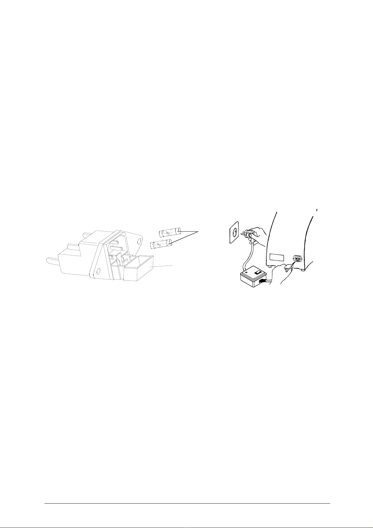
8.3 Checking and replacing the fuses
The fuses should always be checked with a continuity measuring instrument (tester, ohmeter,
multimeter etc.) as a visible check may not reveal an electrical fault. Fuses must always be replaced
with others of the same type (rapid or delayed) and with the same Amps, as shown in the manual.
The NOVA 2000 key-cutting machine has two fuses:
3,15 Amps
rapid for machines with
230 Volt
6,3 Amps
rapid for machines with
115 Volt
placed in the inlet socket, to protect the key-cutting machine from sudden changes in voltage or short
circuits.
It is advisable to check the fuses if the machineis not activated by turning on the master switch. Proceed
as follows:
1) turn off the master switch (P) and remove the mains plug.
2) remove the fuse board with the aid of a screwdriver.
Fig. 15
fuse board
fuses
Table of contents
Other Ilco Orion Cutter manuals


