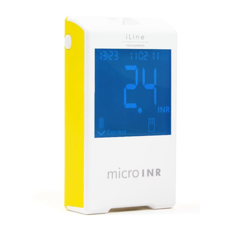
iLine microsystems microINR expert User manual

friendly
technology
INSTRUCTIONS FOR USE

2022-09 New document
Revision Changes
PUBLICATION INFORMATION

TABLE OF CONTENTS
PUBLICATION INFORMATION 0
1.
1.1
1.2
1.3
1.4
2.
2.1
2.2
2.3
2.4
2.5
2.6
2.7
2.8
3.
3.1
3.2
3.3
3.4
3.5
3.6
4.
4.1
4.2
4.3
4.4
4.5
4.6
2
2
2
2
4
4
5
5
6
6
6
7
7
8
8
9
10
11
11
13
15
16
17
19
20
20
20
20
20
21
22
23
23
23
24
25
25
For monitoring oral anticoagulation
treatment based on Vitamin K
antagonist drugs.
microINR®Expert Meter
INTRODUCTION
INTENDED USE
BEFORE USING THE microINR® SYSTEM
Safety Instructions
Quality controls
ORAL ANTICOAGULANT THERAPY
Prothrombin Time and INR
MEASURING PRINCIPLE
microINR Expert METER
microINR Expert KIT DESCRIPTION
microINR Expert METER ELEMENTS
microINR EXPERT ON / OFF
CHARGING THE microINR Expert METER
MENU ICONS OVERVIEW
STATUS BAR AND DROPDOWN
OPERATOR IDENTIFICATION
ADMINISTRATOR IDENTIFICATION
microINR Expert METER CONFIGURATION
SETTINGS
METER SETTINGS
ID SETUP
EASYCONTROL SETTINGS
CONNECTIVITY
ABOUT THIS SYSTEM
CONDUCTING A PATIENT TEST
PREPARING THE REQUIRED MATERIALS
PRIOR STEPS BEFORE THE TEST
MEASUREMENT PROCEDURE
Operator ID & Patient ID
Inserting the Chip
Conducting the Test
Test Result
Adding Comments
Finishing the Test
OBTAINING AND APPLYING THE CAPILLARY
BLOOD SAMPLE
INTERPRETING THE RESULTS
LIMITATIONS OF USE
01
5.
5.1
5.2
6.
7.
8.
8.1
8.2
8.3
8.4
8.5
8.6
8.7
9.
9.1
9.2
9.3
10.
QUALITY CONTROL
PERFORMING microINR EASYCONTROL TEST
Operator ID & microINR EasyControl lot ID
Inserting the Chip
Conducting the Test
microINR EasyControl Test Result
Adding Comments
Finishing the Test
PERFORMING EQA CONTROL
Operator ID & EQA Control lot ID
Inserting the Chip
Conducting the Test
EQA Test Result
Adding Comments
Finishing the Test
TROUBLESHOOTING
MEMORY
Search
Generate Report
ADVANCED FUNCTIONALITIES
BARCODE SCANNER
DATA HANDLING
Wi-Fi
BLUETOOTH
ETHERNET
OPERATOR & PATIENT LISTS
AUTOMATIC DATE / TIME
microINR Expert METER CARE
STORAGE CONDITIONS
TRANSPORT CONDITIONS
CLEANING & DISINFECTION
ADDITIONAL INFORMATION
SPECIFICATIONS
WARRANTY
TECHNICAL SERVICE AND REPORTING
SOFTWARE LICENSE
SYMBOLS
INDEX
26
26
26
27
27
28
29
29
29
30
30
31
32
32
32
33
34
35
35
36
36
36
37
37
38
39
39
40
40
40
40
41
41
41
42
42
42
43
10.1
10.2
10.3
10.4
10.5
11.

1.1 INTENDED USE
The microINR system (Expert), consisting of the microINR Expert meter and the microINR Chips, is intended
to monitor oral anticoagulation therapy (OAT) with vitamin K antagonist drugs. The microINR system (Expert)
determines quantitative prothrombin time (PT) - INR (International Normalized Ratio) units with fresh
capillary blood obtained by fingersticking.
The microINR Expert meter is a medical device for in-vitro diagnostics intended for multiple-patient use by
professional healthcare providers.
1.2 BEFORE USING THE microINR® SYSTEM
These Instructions for Use provide guidelines on handling and use of the microINR Expert meter. Please read
them and the Instructions for Use of the microINR Chips carefully before using the device. There is a USB
flash drive containing these instructions in various languages among the items provided with this meter.
Make sure you also read the instructions of the disposable lancets and/or lancing device used to obtain the
capillary blood sample. These products are not provided with microINR Expert meter.
The term “microINR Expert meter” refers to the reader device.
The term “microINR Chips” refers to the test strips intended to be used exclusively with microINR meters
(microINR, microINR Link and microINR Expert meters).
The microINR system (Expert) refers both to the microINR Expert meter and the test strips (microINR Chips)
and it is intended to be used for near-patient testing and not for self-testing.
Keep these instructions in a convenient place near the microINR Expert meter and refer to them if you have
any queries about proper operation of the system.
The microINR Expert meter is equipped with a touchscreen that displays information and icons about the
meter usage and test results. Users can work with this touchscreen while wearing latex or nitrile gloves.
Throughout these instructions the names of the on-screen options are shown as bold text.
The microINR Expert meter can communicate with a Data Management System (DMS) through wireless
technology (Wi-Fi or Bluetooth) or hard-wired ethernet through the ethernet adaptor (available separately).
The data handling function may vary depending on the particular Data Management System (DMS). Please
contact your local distributor for further information on the DMS compatible with the meter and configuration
required for connection.
You will find a terminology index at the end of these Instructions for Use.
Safety Instructions
This section describes the system safety-related messages and information and how they are presented in
these Instructions for Use.
General Safety Warnings
You will find safety warnings and information on proper use of the microINR system (Expert) throughout
this document.
This warning symbol indicates a potential hazard that could result in death, injury or harm to the
patient or user if the procedures and instructions contained herein are not strictly followed.
This precaution symbol indicates a hazard that could damage the equipment and cause data loss if
the procedures and instructions contained herein are not strictly followed.
Important information regarding proper use of the system that does not affect the safety of the patient
or the integrity of the device is displayed on a blue background.
1. INTRODUCTION
02

User qualification
Users of the microINR Expert meter must receive proper training before using the system.
Infection Risk Control on Multi-Patient Test System
•Users must wear gloves during the entire testing process.
•A new lancet or lancing device must be used for each patient.
•Used chips, lancets and gloves could be source of infection. Dispose of them in accordance with local
regulations to prevent infection.
•Also comply with your center’s internal hygiene and safety regulations.
There is a potential risk of infection. Healthcare professionals using the microINR system (Expert) on
multiple patients must bear in mind that all objects that come into contact with human blood are a
possible source of infection.
Electromagnetic Compatibility and Electrical Safety
The microINR Expert meter complies with electromagnetic compatibility (EMC) requirements according to the
IEC 61326-1 and 61326-2-6 standards.
The microINR Expert meter complies with electrical safety requirements according to the IEC 61010-1 and
IEC 61010-2-101 standards.
Any external device connected to the meter must meet the IEC61010, IEC62368 requirements or the
appropriate component end-product standard.
The microINR Expert meter should not be used adjacent to or stacked with other equipment and if it must
be stacked or used in this way the microINR Expert meter must then be examined to verify normal operation
in the configuration in which it will be used.
Always use cables and accessories provided by the manufacturer. Other cables and accessories may
negatively affect EMC performance.
Avoidance of electrical shock
Do not use cables, chargers and plug adapters different from those provided by the manufacturer.
If you do not follow this requirement, you may damage the meter or yourself. Do not use loose
power sockets or damaged power source units or cables.
Lithium-ion battery
The microINR Expert meter contains an internal lithium-ion battery. Fully charge the battery before using the
meter for the first time. The recommended charging time is approximately 3.5 hours.
Do not open or tamper with the meter.
Do not pierce or burn the battery.
Do not change the battery. The manufacturer’s warranty will not cover meters that have been opened.
The unit must be sent to the manufacturer for battery replacement or repairs to the meter.
Touchscreen
The touchscreen is designed to be used with your finger even when wearing latex or nitrile gloves.
Using other objects could damage the screen.
Disposal of the meter
The meter must be disposed of as indicated in the applicable local and/or national regulations. Bear
in mind that:
Used meters may have been in contact with blood and therefore could be a source of infection.
The meter contains lithium-ion batteries.
03

The meter must be disposed of as indicated in the European WEEE Directive and/or local waste disposal
requirements.
Operating conditions
Use the meter according to the following guidelines to ensure that it works properly:
Only use the meter at room temperature between 15ºC and 35ºC.
Only use the meter at a relative humidity below 80% without condensation.
Place the meter on a flat, stable surface during testing or hold it in your hand and avoid sudden
movements.
Keep the meter away from direct sunlight during the test.
Do not shake or drop the meter. Contact your distributor if the frequency of error messages
increases aer the device has been dropped or has suffered an impact.
Only use the meter at indoor settings with a pollution degree of 2.
Quality controls
The microINR system (Expert) performs automatic quality controls on every test.
Electronic quality control
The microINR Expert meter carries out automatic checks on electronic components, battery power level and
ambient temperature conditions when the system is turned on.
Integrated independent on-board quality controls
On-board controls provide quality control checks for each individual microINR Chip used with the microINR
Expert meter throughout testing.
Level 1 – Pre-test
•Chip integrity check
•Proper insertion check
•Automatic system calibration and rejection of expired chips
Level 2 - Measuring channel
•Analytic verification of measurement for proper pre-analytical treatment of the sample and failures in
processing the sample during the test.
Level 3 - Control channel
•The control channel provides highly-controlled clotting times. The system’s reliability is guaranteed when
the control clotting time is within a pre-defined range.
Liquid control
iLine Microsystems provides an optional liquid control (microINR EasyControl) for the microINR systems. This
control is provided to help meet the regulatory requirements applicable to your facility. Contact your local
distributor if you wish to acquire it.
1.3 ORAL ANTICOAGULANT THERAPY
Oral anticoagulant therapy is prescribed to patients to prevent thromboembolic events such as venous
thrombosis and pulmonary embolism or those linked to atrial fibrillation or artificial heart valves.
The treatment entails the need to periodically monitor and adjust the doses for each patient on the basis of
a blood test.
A therapeutic range is defined for each patient depending on the condition requiring oral anticoagulant
therapy. This means that the test result should lie within a certain range.
The therapeutic range (INR range) will be established by the patient’s healthcare provider on the basis of the
patient’s clinical condition.
04

05
Prothrombin Time and INR
The activity of the vitamin K antagonist drugs is monitored by measuring the prothrombin time (PT) – the
time it takes for a fibrin clot to form – in seconds. Thromboplastin is used as a reagent to calculate the
prothrombin time (PT). Variations of the PT results are to be expected depending on the nature of this
reagent and the equipment employed. Therefore, the World Health Organization (WHO) recommended a
system standardization method in 1977. Prothrombin time values are converted into INR values (International
Normalized Ratio) using the following equation:
where PT is the prothrombin time obtained in the test, MNPT is the mean normal prothrombin time and ISI
the international sensitivity index associated with the thromboplastin. The values of the MNPT and ISI
parameters are taken from clinical calibration studies.
The pharmacological activity of vitamin K-antagonist oral anticoagulants can be modified by other
drugs. Consequently, patients should only take the medicines prescribed by a physician.
Certain liver diseases, thyroid disorders and other diseases or conditions and nutritional supplements,
medicinal herbs or diet changes can affect the therapeutic activity of oral anticoagulants and INR
results.
1.4 MEASURING PRINCIPLE
The technology used by the microINR system (Expert) is based on the microfluidics of the microINR Chip,
which enables storage, dosage, moving and/or mixing small volumes of fluids to obtain a chemical reaction.
The microINR Chips contain two channels, one for measurement and one for control. An image of the chip is
shown below:
Each channel consists of a micro-reactor that contains the reagent and microcapillaries where the PT is
determined. The reagent used in the measuring channel contains human recombinant thromboplastin and
the reagent in the control channel contains recombinant thromboplastin and human coagulation factors to
normalize the patient’s blood.
The blood is applied to the chip through the entry channel which is divided into two channels and mixed with
the reagents contained in each micro-reactor. The coagulation cascade is triggered instantly. When blood
coagulates, a change in blood-flow behavior occurs. The meter captures the position of the sample by means
of a Machine Vision System (MVS) and the position is transformed mathematically into speed and
acceleration curves from which PT-INR values are obtained.
Calibration
Each batch of microINR Chips has been calibrated against a reference batch of human recombinant
thromboplastin traced to International Reference Thromboplastin of the World Health Organization1.
These calibration values (ISI and MNPT) are encoded in the printed Datamatrix of each microINR Chip.
Therefore, every test is automatically and individually calibrated, thus eliminating any risk of human error.
(1) WHO Expert Committee on Biological Normalization. Report forty-eight. Geneva, World Health Organization, 1999 (WHO technical
report series No. 889)
INR =PT ISI
MNPT
( )
ENTRY CHANNEL
MICROREACTORS
DATAMATRIX
MICROCAPILLARY
CHANNELS
CONTROL CHANNEL MEASURING
CHANNEL

2.1 microINR Expert KIT DESCRIPTION
The microINR Expert kit includes:
•microINR Expert meter
•Charger
•Plug adapter
•USB-C cable
•Instructions for Use in English
•USB Flash driver (contains PDF files of the Instructions for Use in other languages)
•Transport Case
The Instructions for Use in English are also available in iLine Microsystems S.L. webpage:
https://www.ilinemicrosystems.com.
Printed copies of the Instructions for Use in other languages can be made available.
Please contact your local distributor for further assistance.
microINR Chips and the ethernet adaptor are sold separately.
Always carry or keep the meter inside its case.
2.2 microINR Expert METER ELEMENTS
06
2. microINR Expert METER
A: Touchscreen
B: Chip insert slot
C: USB-C port
D: Barcode scanner
E: On/Off button
C
A
D
E
B

07
2.3 microINR EXPERT ON / OFF
The microINR Expert meter can be turned on by pressing the ON button located on the upper right side of
the meter or by inserting a microINR Chip into the insertion slot.
The meter can also be switched on by connecting it to the power source,
ethernet adaptor or a computer through the USB-C cable.
The loading screen appears temporarily when the meter is turned on
and the main menu is displayed a few seconds later.
Tap the OFF bar located at the bottom of the main menu to turn
the meter off aer use. A message will be shown to confirm or
cancel shutdown.
The meter will be turned off if the
On/Off button is pressed for a
longer-than-usual time
(10-15 seconds).
2.4 CHARGING THE microINR Expert METER
The meter uses a lithium-ion battery that can be recharged through the USB-C connection on the le side
of the unit with the power source provided in the kit.
The recommended charging time is approximately 3.5 hours.
The battery level is displayed in the battery icon on the
status bar located at the top of the screen. This icon has
four segments, each representing approximately 1/4 of
the total battery capacity.
The following message will appear on the display when the battery is
depleted.
Do not use cables, chargers and plug adapters different from
those provided by the manufacturer. If you do not follow this
requirement, you may damage the meter or yourself. Do not use
loose power sockets or damaged power source units or cables.
The battery charging icon is displayed in the status bar while charging.
Disconnect the meter from the charger and the charger from the socket
once the battery is fully charged.
It is not recommended to charge the meter by connecting it to a
computer.

2.5 MENU ICONS OVERVIEW
2.6 STATUS BAR AND DROPDOWN
Status bar
The status bar is located at the top of most screens and displays the following information:
•Operator or administrator logged on (green) or
logged-off (red).
•Date.
•Wi-Fi, Ethernet, Bluetooth, USB and/or Synchronization.
•Battery icon.
•Time.
Dropdown menu
The dropdown menu can be only displayed by tapping the status bar on
the main menu. The dropdown menu displays the operator/administrator
identification, if a user is logged on and enables the operator/
administrator log-on or log-off.
The available configured communications are also displayed with the
associated icon in blue (or grey if they are not configured).
Tap again on the status bar to return to the main menu.
User logged off Off button
User logged on Data synchronization
Bluetooth Return to main menu
Ethernet Section blocked
USB Option enabled
Battery Option disabled
The meter is connected
to the power supply
Results are displayed
in INR units
Delete; for custom
comments
Search; for Memory
menu
Results are displayed
in seconds
Time between
midnight and noon
(in 12-hour time format)
Time between
noon and midnight
(in 12-hour time format)
Wi-Fi Data synchronization
failed
Clock icon;
for Setting menu
Reports troubleshooting
when an error message
is triggered
Calendar icon;
for Setting menu
08

2.7 OPERATOR IDENTIFICATION
The user who performs the tests may log on either through the dropdown menu or when a patient or QC test
is initiated, depending on the meter’s configuration (see section 3.3).
1. Tap on the status bar in the main menu and then tap on the Log in
button to log on through the dropdown menu.
Select Operator in the User Type section so that the option is highlighted
(bold type with a check mark) and then tap on the Enter ID text entry box.
Enter the identification by means of the barcode scanner by tapping the
Scan OID button if a valid barcode is available. The identification can be
also entered manually using the keypad by tapping the Manual OID button.
Place the barcode at a suitable distance depending on its size to enable
scanning. The meter will emit a beep (provided the beeper is enabled) once
the barcode has been successfully read. The barcode information appears in
Your OID field. The scanner will turn off aer 5 seconds if the barcode is not
scanned (the meter beeps and a Scan error or time-out message is
displayed).
Verify and Confirm the Operator ID or tap Back to restart the Operator identification process.
The User icon changes to green on the status bar once an operator has been identified. The operator’s
identification will be displayed on the dropdown menu.
Tap the Log out button in the dropdown menu and restart the operator identification process if another
operator intends to use the meter.
Each time the meter is turned off, the identified operator will be automatically logged out.
09

2. Depending on the meter’s configuration (see section 3.3), when a patient
or QC test is initiated the meter automatically displays the operator’s log-
on identification options through the barcode scanner and the manual
option with the keypad.
Enter the identification through the barcode scanner if a valid barcode is
available by tapping the Scan OID button. The identification can be also
entered manually using the keypad by tapping the Manual OID button.
Verify and Confirm the Operator ID entered or tap Back to restart the
Operator identification process.
The user icon changes to green on the status bar and the meter continues
with the patient’s identification (depending on the configuration described
in section 3.3) or with identification of the QC material once an operator
has been identified.
Tap the Log out button in the dropdown menu and restart the operator
identification process if another operator intends to use the meter.
Each time the meter is turned off, the identified operator will be automatically logged out.
2.8 ADMINISTRATOR IDENTIFICATION
The administrator has special credentials to access the meter or change
certain settings and is the only person who can do so. The testing menus
(Tests and Quality Control) are deactivated when the administrator is
logged-on.
Tap the Log in button in the dropdown menu to enter the administrator
identification.
Select Administrator in the User Type section so that the option is
highlighted (bold type with a check mark) and then tap the password in the
Enter password text entry box.
Default password: iline
The administrator can change this password (see section 3.3). Changing
the predefined administrator password is recommended as a security
measure.
Key in the proper password using the keypad and confirm the administrator identification by tapping the
Log in button.
The user icon changes to green on the status bar once the administrator has been identified.
The administrator’s identification will be displayed in the dropdown menu.
To log out as administrator, simply tap the Log out button in the dropdown menu.
If the meter is turned off, the administrator will be automatically logged out.
10

11
3. microINR Expert METER CONFIGURATION
3.1 SETTINGS
The microINR Expert settings can be
customized through the Settings option
located in the main menu.
Some of the setting options can be only
entered or changed by the administrator.
If the administrator is not logged on,
these options will be clearly marked in
grey with a padlock symbol.
The following tables show all the setting
options that can be accessed on the
meter.
Meter settings
Screen & Sound
Result
Language
Date / Time Time
Time format
Date
Date format
Auto-Off
Brightness
Beeper
ON* / OFF
1-10 (5*)
ON* / OFF
INR*
INR + PT
Español
English*
Deutsch
Française
Italiano
Dansk
Nederlands
Norsk
Português
Suomi
Svenska
0:00
24 h*
12 h
00/00/0000
DD/MM/YYYY*
MM/DD/YYYY
YYYY/MM/DD
5*/15/30/45 or 60 min
Menu Submenu Setting Values
Administrator logged-off Administrator logged-on

EasyControl Settings
About the system
(*) Default values.
Connectivity
12
ID Setup
Administrator
OID Request
PID Request
EasyControl Lockout
System updates
Software version
More information
Clear memory
Default parameters
Ethernet
Wi-Fi
Bluetooth
POCT1A
ON / OFF*
ON / OFF*
My Network
ON / OFF*
ON / OFF*
Server information
Data Sync
ON / OFF*
Frequency
Lockout Mode
Menu Submenu Setting Values
Menu Section Values
Change password
No
Optional*
Required
No
Optional*
Required
No / Daily / Weekly / Monthly /
Number of tests
Enable test with QC Warning
Meter lockout
Network
User
Password
Test connection
Pair:
Free mode / Password mode
Unpair
Sent data
Address
Port
PID List / OID List
Information
A7
M4
DSP
BT
HW version
SN
Battery

13
3.2 METER SETTINGS
Tap on Settings on the main menu.
Then tap Meter Settings to access the
meter configuration.
Some of the meter’s setting options can be
only entered or changed by the
administrator. If the administrator is not
logged on, these options will be clearly
marked in grey with a padlock symbol
SCREEN and SOUND
The Screen & Sound setup area contains the option for changing
brightness and enables or disables the Beeper function.
Adjust screen brightness by moving the slider from 01 to 10. This
parameter is set at 05 by default.
Enable or disable the Beeper function by sliding the ON/OFF button. This
parameter is ON by default.
When the Beeper function is enabled the meter will emit a beep in the
following cases:
Chip warm-up process is complete and sample application is required.
Sample is detected.
An error has occurred.
A barcode has been scanned.
Scanning error or scanner time-out.
Keeping the Beeper enabled at all times is recommended.
Tap Confirm to save this setting or tap Back to return to the previous screen without saving the changes.
RESULTS
The Results setup area contains the options to select the unit(s) in which
the patient’s result is displayed. This setting must be configured by the
meter administrator (the administrator must be logged on).
•INR: only the results in INR units will be displayed.
•INR + PT: the results in INR units as well as the PT values in seconds (s)
will be displayed.
The selected unit of measure setting is highlighted in bold type with a check
mark. The default setting is INR.
Tap any option to select the preferred unit(s) of measure.
Tap Confirm to save this setting or Back to return to the previous screen
without saving the changes.
Administrator logged-off Administrator logged-on

14
LANGUAGE
Use this setting to select the meter Language.
The selected language is highlighted in bold type with a check mark. The default setting is English.
Tap the selected language on the screen. Tap Confirm to save this setting
or Back to return to the previous screen without saving the changes.
The following languages are available in the meter:
•Español
•English
•Deutsch
•Français
•Italiano
•Dansk
•Nederlands
•Norsk
•Português
•Suomi
•Svenska
DATE / TIME
Use this setting to adjust the Date / Time.
Date
Tap the Calendar icon to manually set the date.
Select the date by moving the wheels to the current date.
The selected date format is highlighted with a check mark. This parameter
is set as DD/MM/YYYY by default.
Tap the selected date format on the screen:
•MM/DD/YYYY: Month/Day/Year, e.g., 09/29/2022
•DD/MM/YYYY: Day/Month/Year, e.g., 29/09/2022
•YYYY/MM/DD: Year/Month/Day, e.g., 2022/09/29
Time
Tap the Clock icon to manually set the time.
Select the time by moving the wheels to the desired time. The time display
items depend on the selected time format.
The selected time format setting is highlighted with a check mark. This
parameter is set as 24-hour by default.
Tap the selected time format on the screen:
•12 h: am/pm option is available with the hours and minutes.
E.g., 02:30 pm
•24 h: am/pm option is not available.
E.g., 14:30
Tap Confirm to save these settings or tap Back to return to the previous
screen without saving the changes.

15
AUTO OFF
The meter can be set to shut down automatically aer a configurable
period of inactivity, as long as no internal process is in progress. The auto
off function is active even when the Meter is charging.
This feature helps to save power and extend battery life. This setting must
be configured by the administrator (the administrator must be logged on).
The auto-off function is enabled aer a 5-minute inactivity period by
default.
Tap Auto off to adjust this option.
Select the inactivity period. It is highlighted in bold type with a check mark.
•5 min
•15 min
•30 min
•45 min
•60 min
Tap Confirm to save this setting or tap Back to return to the previous screen without saving the change.
3.3 ID SETUP
The ID (identification) Setup menu is used to define settings for operator and patient management and for
changing the administrator’s password. These settings must be configured by the administrator (the
administrator must be logged on).
There are three types of user profile used with the microINR Expert meter:
Administrator: The administrator has special credentials to specify
configurable meter settings and is the only one who can enter and change
these settings. The testing menus (Tests and Quality Control) are
deactivated when the administrator is logged-on.
Operator: Operator ID (OID) is assigned to healthcare professionals who
use the meter to perform tests.
Patient: Patient ID (PID) is assigned to the person whose test results are
being recorded.
The meter can restrict its use to specific operators or a predefined group
of users. In this case, an externally-created operator list must be
transferred to the meter by a Data Management System (DMS). See
section 8.6 in these instructions for further details.
Patient lists can also be created externally and transferred to the meter by
a DMS, thus restricting performance of the test to patients identified on
said list. See section 8.6 in these instructions for further details.
Tap Settings from the main menu to define the ID management settings.
Then tap ID Setup to open the three ID types:
Administrator:
The meter has a predefined password for the administrator by default. The
system administrator can change this password. Changing the predefined
administrator password is recommended as a security measure.
Select main menu and tap the status bar to log on as administrator in
the microINR Expert. Follow the steps indicated in section 2.8.
Tap Change to save these settings or tap Back to return to the previous
screen without saving the changes.

16
Operator ID (OID) configuration:
Tap the Operator ID request of choice on the screen:
•No: The meter does not request operator identification when a patient
or QC test is initiated.
•Optional: The meter requests an operator identification when a patient
or QC test is initiated and if the operator has not previously logged on,
but this request may be skipped.
•Required: The meter forces operator identification when a patient or
QC test is initiated and if the operator has not previously logged on.
The selected option is highlighted (bold type with a check mark).
This setting is optional by default.
Tap Confirm to save this setting or tap Back to return to the previous
screen without saving the changes.
Patient ID (PID) configuration:
Tap the Patient ID request of choice on the screen:
•No: The meter does not request patient identification when a patient’s
test is initiated.
•Optional: The meter requests patient identification when a patient’s
test is initiated but this request may be skipped.
•Required: The meter forces patient identification when a patient’s test
is initiated.
The selected option is highlighted (bold type with a check mark).
This setting is optional by default.
Tap Confirm to save this setting or tap Back to return to the previous
screen without saving the changes.
3.4 EASYCONTROL SETTINGS
The EasyControl Settings menu contains options for its configuration.
These settings allow the optional liquid control tests to be run on a desired time basis.
This option is inactive by default.
These settings must be configured by the administrator (the administrator must be logged on).
Lockout, Frequency and Lock Mode
Tap Settings from the main menu to define the EasyControl Settings.
Then tap EasyControl Settings.
Slide the ON/OFF button to activate the EasyControl lockout.
Then set the Frequency for the microINR EasyControl scheme. Tap the
selected frequency on the screen and a new window will open:
•No: the meter will only be locked in case an incorrect EasyControl result
is obtained.
•Daily
•Weekly
•Monthly
•Number of tests: from 1 to 2,000 tests.
Various options can be configured according to the following description
whenever the lockout option is active and the microINR EasyControl test
is not conducted properly or the result is outside the acceptance range:

•Enable test with QC warning: operators may perform tests even if
the QC test was not OK. However, said warning will be displayed
together with the test result.
•Meter lockout: a microINR EasyControl test must be OK before a new
test can be performed.
The selected option is highlighted in bold type and a check mark.
Tap Confirm to save these settings or tap Back to return to the previous
screen without saving the changes.
A microINR EasyControl test must be run in order to initiate the selected
testing frequency.
3.5 CONNECTIVITY
The data transfer options with external devices can be set in the
Connectivity menu. The meter can be connected to a computer or host
system (DMS) through various channels. The data handling function may
vary depending on the particular Data Management System (DMS).
Please contact your local distributor for further information on the DMS
compatible with the meter and configuration required for connection.
These connectivity settings must be configured by the administrator (the
administrator must be logged on). See section 8.2 in these instructions
for further information on the meter’s data handling and connectivity
features.
Tap Settings in the main menu and then tap Connectivity to define the
system connectivity.
There are four options to choose from:
Ethernet: enable the Ethernet by sliding the ON/OFF button.
The meter must be connected to the ethernet adaptor (available
separately) to communicate with a Data Management System (DMS)
through the Ethernet.
It is also necessary to configure the POCT1A settings to communicate
with a DMS via Ethernet.
Wi-Fi: The microINR Expert meter can communicate and transfer results
to a DMS by Wi-Fi to a specific Access Point (AP) Wireless Local Area Network (WLAN). The meter recognizes
the existing AP WLAN protocol configuration (802.11b, 802.11g or 802.11n) and automatically transmits
data using the POCT1-2A communication protocol.
Enable the Wi-Fi by sliding the ON/OFF button to set the Wi-Fi Settings and connect to a specific WLAN.
Then fill in the network details:
•SSID: tap the text entry box to type the network name using the keypad.
17

•User: tap the text entry box to type the username using the keypad.
•Password: tap the text entry box to type the network password using
the keypad.
The username and password details may not be necessary. In this case
leave the field blank.
A Test connection can be performed to check proper communication
with the WLAN once all the network details have been filled in.
Tap Confirm to save these settings or tap Back to return to the previous
screen without saving the changes.
It is also necessary to configure the POCT1A settings to be able to
communicate via Wi-Fi with a DMS.
Bluetooth: The microINR Expert meter can communicate and transfer results to a DMS or other electronic
devices (suitable smartphone/tablet Apps) through wireless Bluetooth connection.
Enable Bluetooth on the meter by sliding the ON/OFF button to set the Bluetooth Settings.
When Bluetooth is on the meter can be paired with a compatible device
in two different configurable modes:
•Free mode: follow the instructions on the compatible software or
smartphone/tablet app to pair the meter.
•Password mode: the microINR Expert meter shows a 6-digit password.
Type the password on the compatible device and follow the software
or app instructions.
The selected option is highlighted in bold type and a check mark.
Then, complete the connection process by tapping the Pair button to link
the meter with a compatible device. The microINR Expert meter can only
be paired with one device at a time.
The Unpair and Send data options will be available once the meter has
been paired:
•Unpair: tap this option to unpair the meter from the connected device.
•Send data: tap this option to send all the results performed with the Bluetooth activated.
Tap Confirm to save these settings or Back to return to the previous screen without saving the changes.
Notice that the meter will only be able to transmit results via Bluetooth if they have been obtained with
the Bluetooth setting activated. If results are obtained when the Bluetooth is deactivated, they cannot be
subsequently sent via Bluetooth.
POCT1A: The microINR Expert meter supports data exchange via the
POCT1A standard either through Wi-Fi or Ethernet.
Fill in the Server information details to configure the POCT1A Settings:
•Address: tap the text entry box to type the server address using the keypad.
•Port: tap the text entry box to type the server port using the keypad.
The meter may also receive an operator and/or patient list from a DMS.
Select the Operator lists and/or Patient list to enable these options.
The selected option(s) is highlighted in bold type and a check mark. See
section 8.6. to learn more about this feature.
Tap Confirm to save these settings or tap Back to return to the previous
screen without saving the changes.
18
Table of contents
Other iLine microsystems Personal Care Product manuals