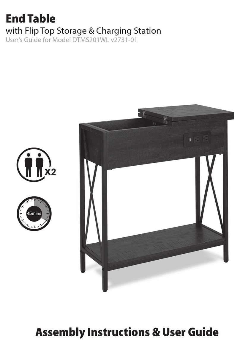
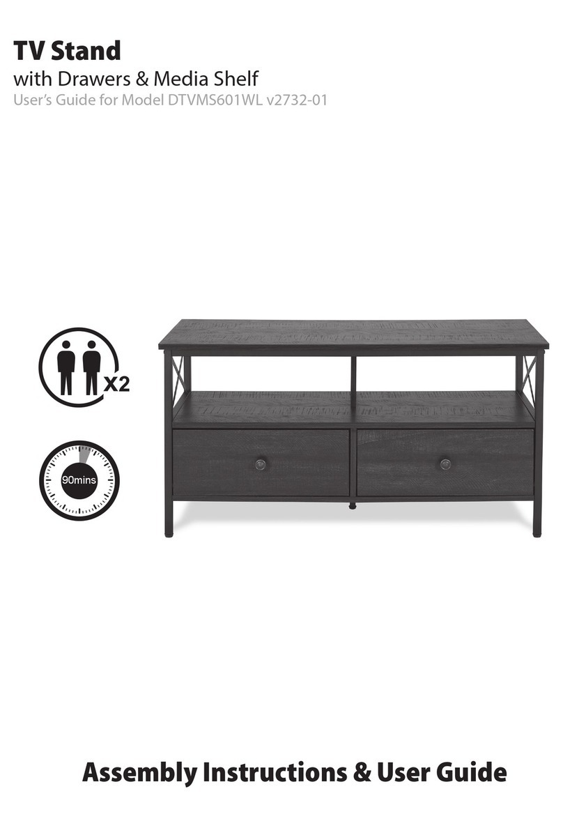
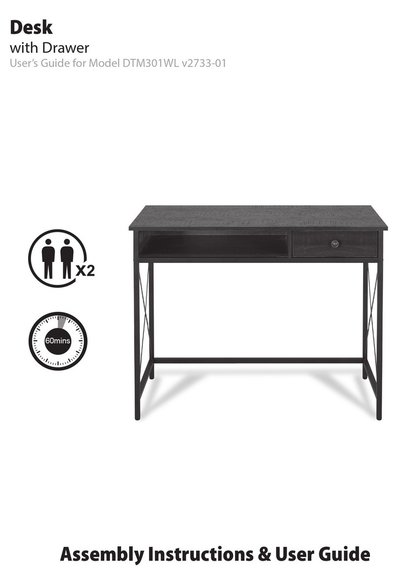
iLive DTMAC701WL User manual

5 Tier Bookcase
with Drawer & Charging Station
User’s Guide for Model DTMAC701WL v2730-01
Assembly Instructions & User Guide
60mins

2 3
SAFETY WARNINGS
•WARNING: To prevent re or shock hazards, do not expose this unit to
rain or moisture.
•Clean only with a dry cloth. Do not clean with liquid cleaners or a damp cloth.
• DO NOT use with devices that should not be used unsupervised.
• DO NOT use in a bathroom or other locations where it may come into contact
with water or splashing.
• WARNING: Where the mains plug or appliance coupler is used as the
disconnect device, such disconnect device shall remain readily operable
• Risk of electric shock. Grounding continuity must be maintained.
•SAVE THESE INSTRUCTIONS
• DO NOT connect the power strip to an ungrounded outlet.
• DO NOT use the power strip with 2-wire extension cords or adapters.
• This power strip is designed for indoor use only. Do not install near any heat
sources such as radiators, heat registers, stoves, or other apparatus (including
ampliers) that produce heat.
• DO NOT install where excessive moisture is present.
• DO NOT plug extension cords into the power strip.
• Never install electrical, telephone, network or coaxial wiring during a
lightning storm.
• DO NOT drill into any part of the housing or open the housing for any reason.
There are no user-serviceable parts inside.
FCC WARNINGS
Warning: Changes or modications to this unit not expressly approved by the party
responsible for compliance could void the user’s authority to operate the equipment.
NOTE: This equipment has been tested and found to comply with the limits for a Class
B digital device, pursuant to Part 15 of the FCC Rules. These limits are designed to provide
reasonable protection against harmful interference in a residential installation. This
equipment generates, uses, and can radiate radio frequency energy and, if not installed
and used in accordance with the instructions, may cause harmful interference to radio
communications. However, there is no guarantee that interference will not occur in a
particular installation. If this equipment does cause harmful interference to radio or
television reception, which can be determined by turning the equipment o and on, the user
is encouraged to try to correct the interference by one or more of the following measures:
• Reorient or relocate the receiving antenna.
• Increase the separation between the equipment and receiver.
• Connect the equipment into an outlet on a circuit dierent from that to which the
receiver is connected.
• Consult the dealer or an experienced radio/TV technician for help.
WARNING: This product can expose you to chemicals
including lead, which is known to the State of California to cause
cancer and birth defects or other reproductive harm. For more
information go to www.P65Warnings.ca.gov. This product meets
and complies with required Federal product guidelines.
Safety & Warnings Features
8kg weight limit (17.6 lbs)
2 AC sockets
2 USB ports
Bookshelf with paper laminated drawer
Includes
AC cord set with AC sockets and USB ports
Assembly hardware
User’s Guide and assembly instructions

4 5
What you will need
Flathead Screwdriver
Phillips-Head Screwdriver
Do not use a power
drill.
ASSEMBLY TOOLS REQUIRED (NOT INCLUDED)
Maintenance
Thank you for your purchase. This product has been designed for easy assembly and
constructed for durability. All parts were checked prior to packaging to ensure quality.
Prior to beginning assembly, please make sure all parts and hardware are included and
free of defect. If a part is missing or defective, please contact the place of purchase.
To ensure you furniture maintains its quality and longevity, please
follow the following care suggestions.
1. Keep out of direct sunlight so the color is preserved.
2. Dust or wipe clean with a damp cloth. Be sure not to leave water spots on the surface.
These water spots will dry and could possibly leave permanent marks.

6 7
Before assembly
Tips before your start:
- Remove all wrapping material, including staples & packing straps before you start to
assemble.
- DO NOT tighten all screws and bolts until completely assembled.
- Keep all hardware parts out of reach of children.
QUICKFIT
Tighten quickt until shoulder is ush with panel. Do not overtighten or undertighten.
CAM LOCK
When tting cam lock, ensure starting position is correct before you insert connecting
quickit.
Quickt head should be in the
Center of the cam lock when the
two panels are joined.
Cam lock should be inserted before
quickt.
Turn cam lock clockwise to tighten.
Charging
1. To use the USB ports and AC outlets, you must rst assemble the
table using the assembly instructions.
2. Plug the table’s power cord into a standard wall outlet.
3. Plug your electronics devices into the table to and the table will
power them.
This end table includes 2 USB ports and 2 AC outlets that can power
your electronics and devices

8 9
Part list
When unpacking, please be careful not to discard any parts with the packaging.
Before continuing, please make sure you have the following parts:
Drawer
bottom panel
Drawer front
panel
Drawer back
panel
Drawer left
side panel
Drawer right
side panel
NO
12
4
6
8
Description Description
Qty Sketch
Top panel Left frame
NO Qty Sketch
Left frame
Shelf
1 1
110
31
Stretcher
1
1
Left side
panel 1
1
Right frame
Right frame
10
3
5
7
9
Bottom panel 1
12
Back panel 1
11
1
14
1
13
15
17
1
16
1
1
Top panel
Right side
panel
1
6
7
2
5
5
35
4
4
4
4
4
4
4
4
4
4
8
9
10
11
15
16
17
12
13
14

10 11
Hardware list
When unpacking, please be careful not to discard any parts with the packaging.
Before continuing, please make sure you have all of the following hardware:
Gx2 Hx2
Bx8 Cx8 Ex2
Dx2
Bolt
Ax8
Fx8
Screw Screw Allen Key
Jx1
Cam Bolt
Ix20
Cam Lock Wooden Dowel Cabinet Slider Drawer Slider
Handle
Lx2 Mx2
Rx6
Kx30
Screw
Px4
Bolt
Screw
Ox2
Nx2
Sx6
Anti-tip Bracket
Qx10
Screw
Anchor Washer
USB
Buckle
Tx4
Screw Leveler
Step 1
Step 2
2xP
2
3
P
P
P
2
3
J

12 13
Step 3
Step 4
2xP
Step 5
7
6
P
P
7
PJ
6
2
3
7
4
44
4
4
44
44
4
I
I
J
6
Do not tighten ANY bolts until entire unit is set up!
Please screw from the
side with counterbore.
20xI

14 15
Step 6
Step 7
2xL
6xK
Step 8
Step 9
6xK
1
K
K
KK
K
K
L
L
2
3
7
K
L
14
6
5
K
K
KK
K
K
5
D
E
D
E
SAFETY RELEASE TAB
Slider
Dx2 and Ex2
D and E are shipped together
to maintain the oil for the
ball bearings. Note that you
need to pull up the safety
release tab to seperate the
two parts prior to assembly.

16 17
Step 10
Step 11
4xC
4xQ
Step 12
Step 13
4xB
USB
2xD
4xA
D
Q
QQ
Q
D
9
10
A
A
A
C
C
A
A
C
C
8
2xQ
B
B
B
B
8
9
10
8
9
10
Q
Q

18 19
Step 14
Step 15
4xF
4xC
Step 16
Step 17
6xK
11
8
9
10
C
8
9
10
F
12
12
11
10
7
6
2
3
9
K
K
K
K
K
K
12
Notice: When xing the panel and metal frame,
please adjust the distance between panel and
metal frame to be consistent, then lock the
screws.

20 21
Step 18
Step 19
6xK
Step 20
Step 21
4xT
6xK
5
K
KK
K
K
K
5
5
5
K
K
K
K
K
K
T
T
T
T
Gently Tighten All Bolts.

22 23
Step 22
Step 23
4xB
2xO
2xN
4xA
Step 24
Step 25
6xS
4xF
6xR
2xM
N
O
M
M
N
O
WARNING: ENSURE THAT
WALL STRAP IS ATTACHED TO
AVOID SERIOUS INJURY
To avoid any serious injury, this
product has been supplied with
a wall strap to prevent toppling.
We strongly recommend that this
product is permanently xed to the
wall or another suitable surface.
A
B
13
14
17
16
15
13
14
17
F
R
S
16
R
S

24 25
Step 26
Step 27
2xH
4xQ
2xE
2xG
Step 28
E
E
Q
Q
Q
Q
13
14
17
If needed, adjust lev-
elers (T) to level the
bookcase.
Notice: tighten this screw rst
17
H
G

26 27
Drawer Installation Guide
• Before you insert the drawers into the frame, please ensure that the ball bearing sliders
(on the assembled unit) have been placed to the front of the main unit. If the bearings are
in the middle of the slider it will be dicult to install the drawers correctly.
D D
• Insert the drawer into the assembled frame as show below. Keep each side of the drawer
straight and aligned correctly to the sliders on the assembled frame.
BODY
LEFT RIGHT
TOP VIEW
DRAWER
BODY
LEFT RIGHT
TOP VIEW
DRAWER
• Gently start to push the drawer into position, the drawer sliders should start to connect
with the sliders on the assembled frame. Once connected, apply even pressure to each
side and gently push the drawer into place.
• The ball bearings should catch the drawer sliders, once they do, you may nd that
you need to apply more pressure, this is perfectly normal as long as you are keeping the
drawers straight, push the drawers 100% of the way in. Finally slide drawer in and out a
few times to ensure the ball bearings are running smoothly in the slider. Installation is
complete.
• At any stage throughout the install process you feel like the drawers are not evenly
sliding into the assembled frame, please remove the drawers before they start to attach to
the bearing slider and start the install steps again.
NOTE
CAUTION
When removing the drawer, please
pull up on the safety release tab on
the left and right side to remove the
drawer from the body as shown.

Protect for Today
Sustain for Tomorrow
Made
Green
Customer Support
Copyright © 2021 Digital Products International (DPI, Inc.). All other trademarks appearing
herein are the property of their respective owners. Specifications are subject to change
without notice.
For Warranty Information, the most up-to-date version of this User’s
Guide or to download this User’s Guide in English, French or Spanish,
please go to: www.iLiveElectronics.com
Customer Service: 1-888-999-4215
Table of contents
Other iLive Indoor Furnishing manuals
Popular Indoor Furnishing manuals by other brands

Home affaire
Home affaire 77507105 Assembly instructions

Stanley
Stanley DELUXE CLOSET SYSTEM Assembly instructions

J&K
J&K WMDC2430H Assembly instructions

LDI
LDI SAFCO Value Mate 7172 Assembly instructions

Arthur Berndt
Arthur Berndt Alessio 520 Assembly instructions

Coaster
Coaster 110698 Assembly instructions