2 3
SAFETY WARNINGS
•WARNING:To prevent re or shock hazards, do not expose this unit to
rain or moisture.
•Clean only with a dry cloth. Do not clean with liquid cleaners or a damp cloth.
• DO NOT use with devices that should not be used unsupervised.
• DO NOT use in a bathroom or other locations where it may come into contact
with water or splashing.
• WARNING:Where the mains plug or appliance coupler is used as the
disconnect device, such disconnect device shall remain readily operable
• Risk of electric shock. Grounding continuity must be maintained.
•SAVE THESE INSTRUCTIONS
• DO NOT connect the power strip to an ungrounded outlet.
• DO NOT use the power strip with 2-wire extension cords or adapters.
• This power strip is designed for indoor use only. Do not install near any heat
sources such as radiators, heat registers, stoves, or other apparatus (including
ampliers) that produce heat.
• DO NOT install where excessive moisture is present.
• DO NOT plug extension cords into the power strip.
• Never install electrical, telephone, network or coaxial wiring during a
lightning storm.
• DO NOT drill into any part of the housing or open the housing for any reason.
There are no user-serviceable parts inside.
FCC WARNINGS
Warning: Changes or modications to this unit not expressly approved by the party
responsible for compliance could void the user’s authority to operate the equipment.
NOTE: This equipment has been tested and found to comply with the limits for a Class
B digital device, pursuant to Part 15 of the FCC Rules.These limits are designed to provide
reasonable protection against harmful interference in a residential installation.This
equipment generates, uses, and can radiate radio frequency energy and, if not installed
and used in accordance with the instructions, may cause harmful interference to radio
communications. However, there is no guarantee that interference will not occur in a
particular installation. If this equipment does cause harmful interference to radio or
television reception, which can be determined by turning the equipment o and on, the user
is encouraged to try to correct the interference by one or more of the following measures:
• Reorient or relocate the receiving antenna.
• Increase the separation between the equipment and receiver.
• Connect the equipment into an outlet on a circuit dierent from that to which the
receiver is connected.
• Consult the dealer or an experienced radio/TV technician for help.
WARNING: This product can expose you to chemicals
including lead, which is known to the State of California to cause
cancer and birth defects or other reproductive harm. For more
information go to www.P65Warnings.ca.gov.This product meets
and complies with required Federal product guidelines.
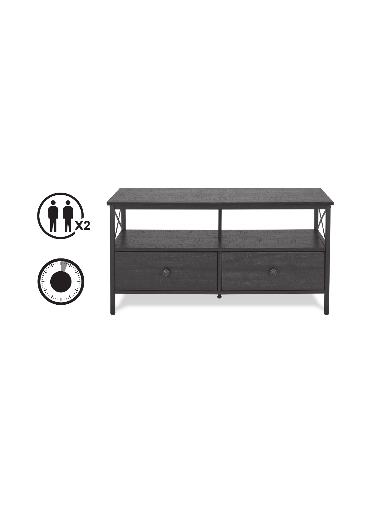
Safety & Warnings Features
10kg weight limit (22 lbs)
TV Stand with paper laminated drawer
Includes
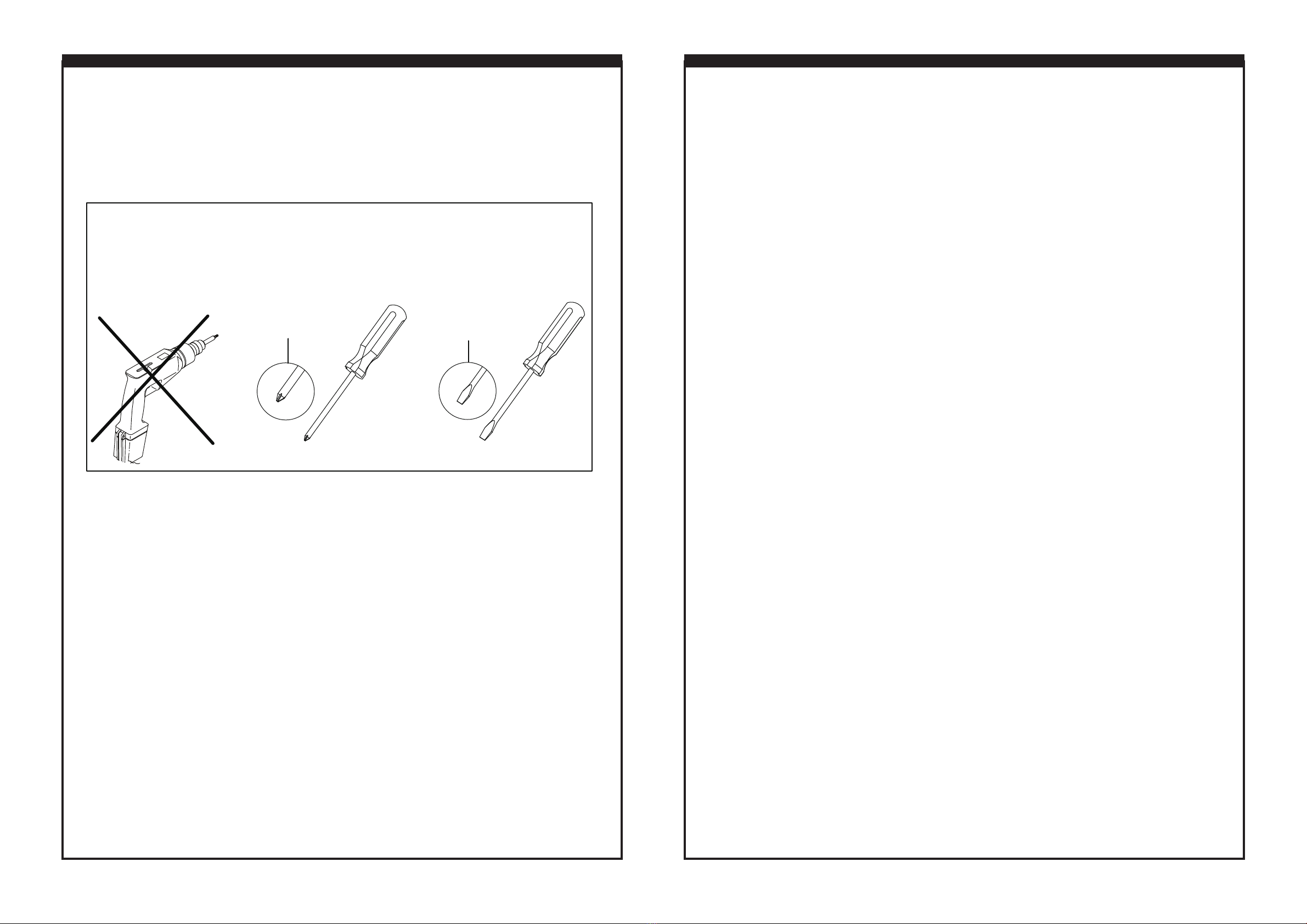
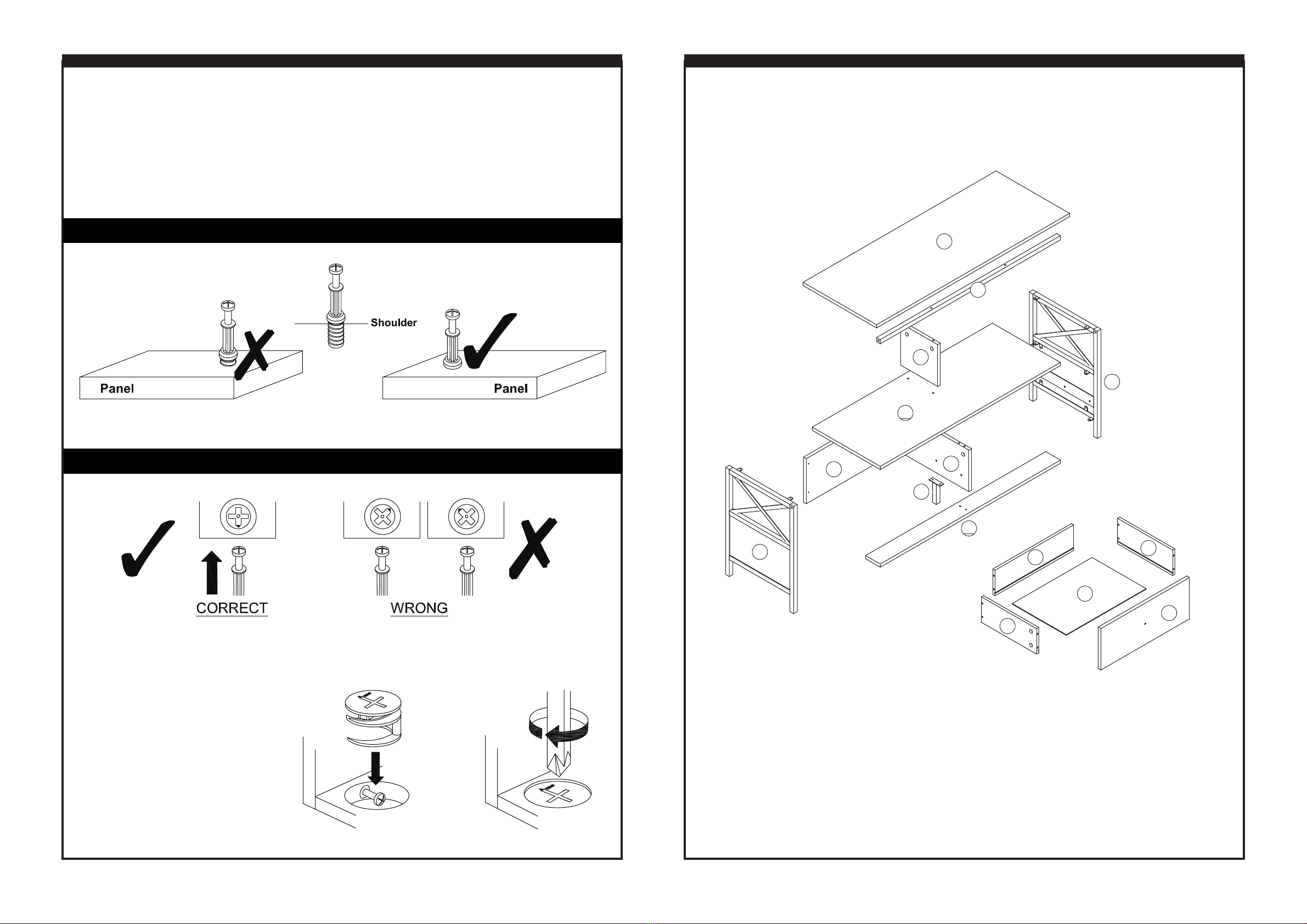
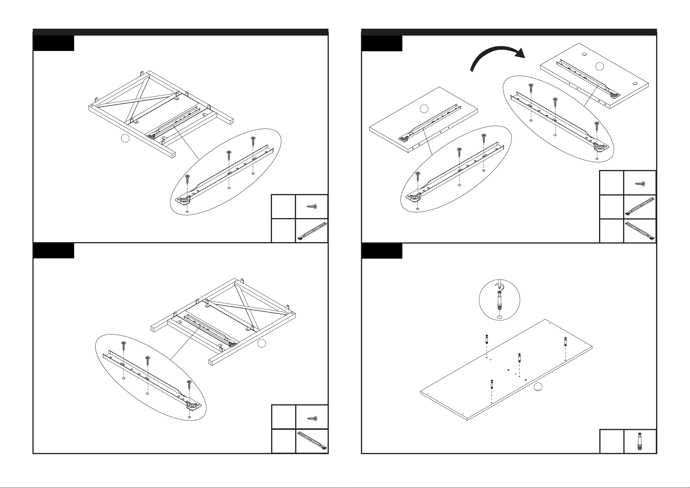
Assembly hardware
User’s Guide and assembly instructions