Illinois Tool Works 400386UB User manual

Operations
Manual
Piezo InkJet System
400386UB
Revision A

Piezo Inkjet System
Operations Manual
400386UB
The information contained in this manual
is correct and accurate at the time of its
publication. ITW reserves the right to
change or alter any information or
technical specifications at any time and
without notice.
©2023 Illinois Tool Works Inc.
All rights reserved

This Piezo InkJet system, including all components unless otherwise specified, carries a limited warranty.
The inks and conditioners used with this system carry a limited warranty.
For all warranty terms and conditions, contact your reseller for a complete copy of the Limited Warranty Statement.
Warranty:
Piezo InkJet System

Section 1: Safety and Ink Usage ..........................................................................................................................................................................6
Section 2: Quick Start ...........................................................................................................................................................................................7
Step 1: Assemble Bracketry to Conveyor ...................................................................................................................................................8
Step 2: Assemble Printer onto Bracketry ....................................................................................................................................................9
Step 3: Mount and Connect Power Supply ...............................................................................................................................................10
Step 4: Mount Photosensor and Encoder ..................................................................................................................................................11
Step 5: Daisy-Chain Printers, HMI, and/or Customer Network ...............................................................................................................12
Step 6: Powering up the Printers ...............................................................................................................................................................14
Step 7: Adjust Printer to Substrate ............................................................................................................................................................15
Step 8: Printer Level and Tilt ....................................................................................................................................................................16
Step 9: Install Ink Cartridge ......................................................................................................................................................................17
Step 10: Priming the Printer and Testing Print Quality ............................................................................................................................18
Step 11: Cap Unused Ports .......................................................................................................................................................................19
Step 12: Create a Message and Control the Printer ..................................................................................................................................19
Section 3: Maintenance and Shutdowns ...........................................................................................................................................................20
System Maintenance .................................................................................................................................................................................20
Printer Module Maintenance ....................................................................................................................................................................20
Ink Supply Module Maintenance ..............................................................................................................................................................21
Printer Shutdown ......................................................................................................................................................................................21
Cleaning Maintenance System ..................................................................................................................................................................22
Printer Module Replacement ....................................................................................................................................................................23
Section 4: Troubleshooting ................................................................................................................................................................................24
Print Quality ..............................................................................................................................................................................................24
System .......................................................................................................................................................................................................29
Appendix A: System Specifications ...................................................................................................................................................................32
System .......................................................................................................................................................................................................32
Controller HMI .........................................................................................................................................................................................33
2" Printer ...................................................................................................................................................................................................34
4" Printer ...................................................................................................................................................................................................35
System Interconnect Diagram ...................................................................................................................................................................36
Customer System Connection ...................................................................................................................................................................37

Appendix B: Theory of Operation ....................................................................................................................................................................38
Functional Description ..............................................................................................................................................................................38
2" and 4" Printer ........................................................................................................................................................................................38
ISM Features .............................................................................................................................................................................................39
Ink States ...................................................................................................................................................................................................40
Printer Daisy Chain ...................................................................................................................................................................................41
Print Trigger Photosensor .........................................................................................................................................................................41
Encoder .....................................................................................................................................................................................................41
Appendix C: Diagrams .......................................................................................................................................................................................42
ISM Main CPU PCB Assembly ................................................................................................................................................................42
ISM Internal Wiring Diagram ...................................................................................................................................................................43
Appendix D: Ink ..................................................................................................................................................................................................44
Storage Life of a FACTORY SEALED Cartridge of Ink .........................................................................................................................44
Use Life of an OPENED Cartridge of Ink ................................................................................................................................................44
Storage Life of the Printer Module or Ink Supply Module .......................................................................................................................44
Appendix E: Updating the ISM Firmware via USB ........................................................................................................................................44
Appendix F: Software Interface ........................................................................................................................................................................44
Appendix G: Part Numbers ...............................................................................................................................................................................45
System .......................................................................................................................................................................................................45
Printer Replacement Parts .........................................................................................................................................................................46
Bracketry ...................................................................................................................................................................................................47
Fittings ......................................................................................................................................................................................................48
Cables ........................................................................................................................................................................................................48
Service Parts and Optional Equipment .....................................................................................................................................................49

Piezo InkJet System Section 1: Safety and Ink Usage
400386UB Operations Manual Rev A Page 6
Section 1: Safety and Ink Usage
Following is a list of safety symbols and their meanings, which are found throughout this manual. Pay attention to these symbols where they
appear in the manual.
Wear safety goggles when performing the procedure described!
Caution! Denotes possible minor or moderate injury and/or damage to the equipment.
Caution! Denotes possible minor or moderate injury and/or equipment damage due to electrical hazard.
NOTE: (Will be followed by a brief comment or explanation.)
ESD protection should be worn when servicing internal printed circuit boards.
After service to the equipment is completed, replace all protective devices such as grounding cables and covers before operating the equipment.
Service is to be performed by trained personnel only.
It is extremely important to:
• Clean up all spills and dispose of all waste according to local and state regulations.
• Wear safety glasses and protective clothing, including gloves, when handling all inks and conditioners.
• Store inks and conditioners under the recommended conditions found on the SDS (Safety Data Sheet).
CAUTION: The Ink Supply Module contains hazardous voltage (90VDC). Disconnect from mains power before:
• Performing preventive maintenance.
• Performing any repairs to the unit.
• Servicing the equipment in any manner.
Caution: Denotes possible personal injury due to sharp object.
Piezo InkJet System Section 2: Quick Start
400386UB Operations Manual Rev A Page 7
Section 2: Quick Start
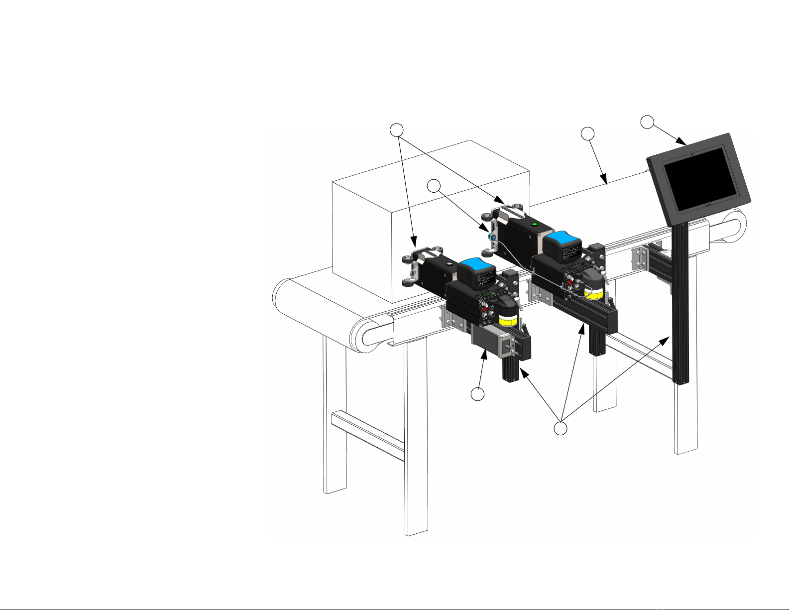
The figure at right illustrates a typical installation.
System Components:
1. Bracketry Kit (Item 1)
2. Printers (Item 2)
3. HMI (Item 3)
4. Power Supply (Item 4)
5. Photosensor (Item 5)
6. Encoder (Item 6)
7. Power Cord (not shown)
8. Ethernet Cable (not shown)
9. Software (not shown)
10. Ink (not included)
TYPICAL INSTALLATION
4
3
1
2
5
6

Piezo InkJet System Section 2: Quick Start
400386UB Operations Manual Rev A Page 8
Step 1: Assemble Bracketry to Conveyor
1. Firmly tighten all fasteners.
NOTE: Ensure bracketry is square and level.
PRINTER
CONVEYOR MOUNT
(400201 FOR 2" PRINTER)
(400204 FOR 4" PRINTER)
OPTIONAL HMI
CONTROLLER / MOUNT
(5765250)

Piezo InkJet System Section 2: Quick Start
400386UB Operations Manual Rev A Page 9
Step 2: Assemble Printer onto Bracketry
ROLLER / RETRACTING
BRACKET MOUNT
(for 2" Printer)
(400201)
DOVETAIL ADAPTER AND
RETRACTING BRACKET
AND CAN BE MOUNTED
ON EITHER SIDE OF
PRINTER
ROLLER / RETRACTING
BRACKET MOUNT
(for 4" Printer)
(400204)
NOTE: The dovetail adapter and mounting bracketry can be
mounted on either side of the Printer.

Piezo InkJet System Section 2: Quick Start
400386UB Operations Manual Rev A Page 10
Step 3: Mount and Connect Power Supply
1. Install power supply with power cord mains facing the conveyor and DC output facing out towards the rear of the Printer.
2. Firmly tighten fasteners to bracketry or convenient location.
NOTE: One power supply pack can power up to two Printers in any combination of 2" or 4".
Piezo InkJet System Section 2: Quick Start
400386UB Operations Manual Rev A Page 11
Step 4: Mount Photosensor and Encoder
Photosensor
1. Mount the photosensor (kit 400203) in the roller bracket attached to the Primary Printer Module
and route the cable as shown in one of the two shown configurations depending on the
application.
NOTE: When viewing from the rear for the Printer, mount on the left side for left to right moving
cartons, and vice versa on right to left.
2. Insert the photosensor cable connector into the appropriate connector on the rear of the Primary
Printer Ink Supply Module.
Encoder
1. Install the encoder (kit 400206) in a location where it will accurately measure the speed of the
conveyor.
2. Install it in contact with the conveyor belt or with a roller moving the same speed as the conveyor.
3. Insert the encoder cable into the Primary Printer Ink Supply Module.CAUTION: Do not
excessively pre-load the encoder wheel. A radial force of over 18,14 kg [40 lbs] will reduce the
life of the bearings.
CAUTION: Do not excessively pre-load the encoder wheel. A radial force of over 18,14 kg [40lbs]
will reduce the life of the bearings.
Photosensor
Mounting &
Cable
Routing
Encoder
Input
Photosensor
Input
Conveyor
Encoder Spring
Encoder Wheel
Piezo InkJet System Section 2: Quick Start
400386UB Operations Manual Rev A Page 12
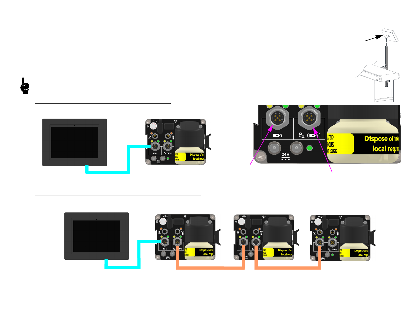
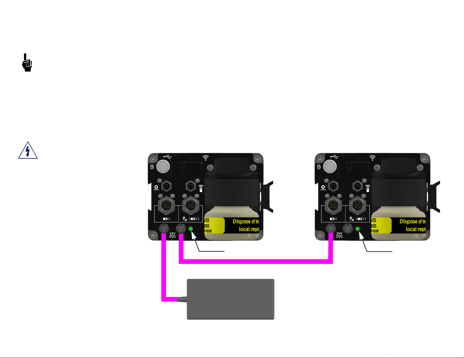
Step 5: Daisy-Chain Printers, HMI, and/or Customer Network
1. Install secondary Printers as shown in the previous steps.
2. Secondary Printers should be connected between the upstream Printer Ethernet out port to the input port on its
Printer as shown as shown in the diagrams below. Up to eight Printers can be daisy chained together.
3. Install the HMI / Controller on appropriate bracketry.
4. Connect the HMI or Laptop / PC via Ethernet cable (400374-2.0) as shown in the below diagrams.
NOTE: Alternatively, the Primary Printer can be connected to the HMI via wireless. Consult the create and control
manual (400463).
Standalone System with HMI - One Printer
Standalone System with HMI - Two or More Printers
OPTIONAL
HMI
FROM UPSTREAM
PRINTER
TO DOWNSTREAM
PRINTER OR HMI
HMI PRIMARY PRINTER
HMI SECONDARY PRINTER PRIMARY PRINTER
SECONDARY PRINTER
Piezo InkJet System Section 2: Quick Start
400386UB Operations Manual Rev A Page 13
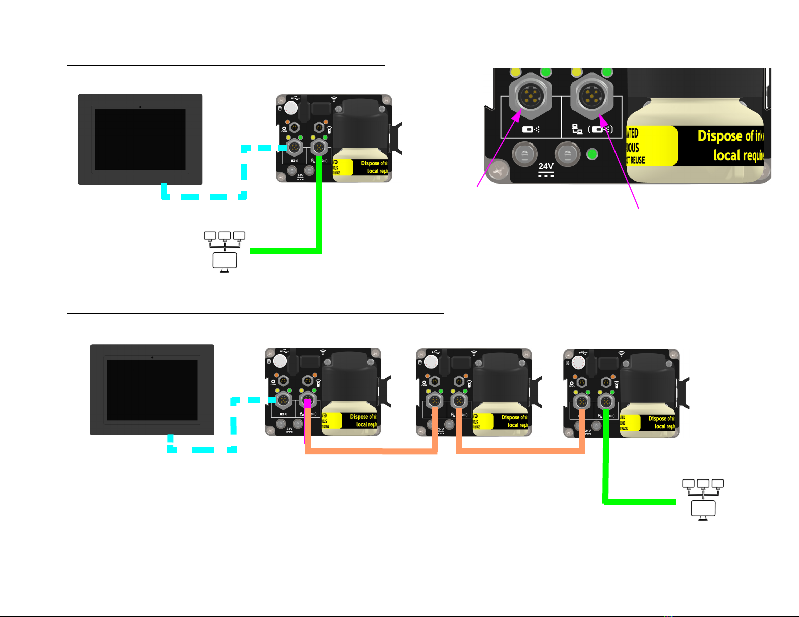
Networked System with Optional HMI - One Printer
Networked System with Optional HMI - Two or More Printers
HMI PRIMARY PRINTER
FROM UPSTREAM
PRINTER OR
CUSTOMER NETWORK
TO DOWNSTREAM
PRINTER OR HMI
CUSTOMER NETWORK
HMI SECONDARY PRINTER PRIMARY PRINTER
SECONDARY PRINTER
CUSTOMER NETWORK
Piezo InkJet System Section 2: Quick Start
400386UB Operations Manual Rev A Page 14
Step 6: Powering up the Printers
5. Install the power cord into the first Printer in the system (from now on called the Primary Printer).
The power supply cable or jumper cable can be plugged into either power port.
Do not over-tighten with pliers.
6. If there is more than one Printer, the Primary should be the Printer to have product pass by it first; therefore, it should have the photocell
mounted to it on the leading edge.
7. Ensure the power connector is fully inserted and the threaded barrel is finger tight.
8. Connect any downstream Printers from the Primary. These are considered Secondary.
9. Only one Secondary Printer can be powered by an upstream Printer. An additional power supply will be required for every two Printers on a
daisy chain, regardless of Printer type / size.
10. Plug the A/C cord into the mains.
Best practices are to plug power
into the Printers first before the
A/C mains.
TYPICAL INSTALLATION
PRIMARY PRINTER SECONDARY PRINTER
POWER LED POWER LED
POWER JUMPER CABLE P/N 400490
POWER SUPPLY P/N 400380
Piezo InkJet System Section 2: Quick Start
400386UB Operations Manual Rev A Page 15
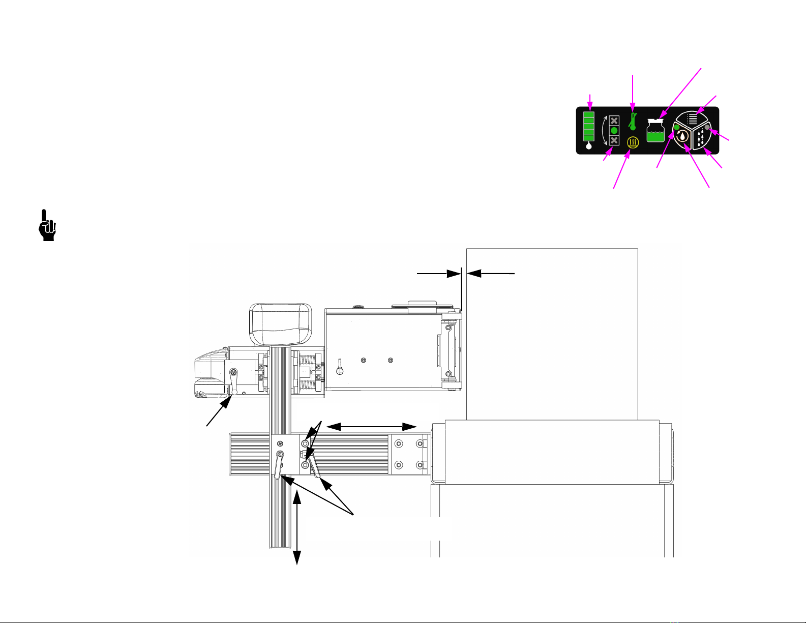
Step 7: Adjust Printer to Substrate
1. Tighten bracketry to conveyor such that the Printer is perpendicular to the carton; however,
ensuring that the Printer is level from front to back. See "Step 8: Printer Level and Tilt" on page
16.
2. Use vertical tool-less handles to adjust Printer to approximate printing height position. Tighten
handles.
3. While horizontal adjustment slide bracketry screws are loose, adjust vertical bracket with
Printer horizontally to within 6 mm (1/4 in) of the carton.
4. Use the dovetail tool-less handle to make fine adjustments between the Printer rollers and
carton to within 1 mm - 2 mm (.04in - .08 in).
NOTE: Printer print gap can be adjusted to be larger in heavy debris environment but must be
balanced with print quality.
CLEAN / PRIME
BUTTON
AT TEMPERATURE LED
RECIRCULATION
LED
HEATER ON LED RECIRCULATION
BUTTON
WASTE BOTTLE
STATUS LED
INK CARTRIDGE
STATUS LEDs
PRINTER LEVEL
LEDs
CLEAN / PRIME
LED
ALL CHANNEL
PRINT BUTTON
HORIZONTAL ADJUSTMENT
SLIDE BRACKETRY SCREWS
CONVEYOR
CARTON
1 mm - 2 mm (.04in - .08in)
PRINT GAP RECOMMENDED
DOVETAIL
TOOL-LESS
HANDLE
VERTICAL ADJUSTMENT
TOOL-LESS HANDLES
Piezo InkJet System Section 2: Quick Start
400386UB Operations Manual Rev A Page 16
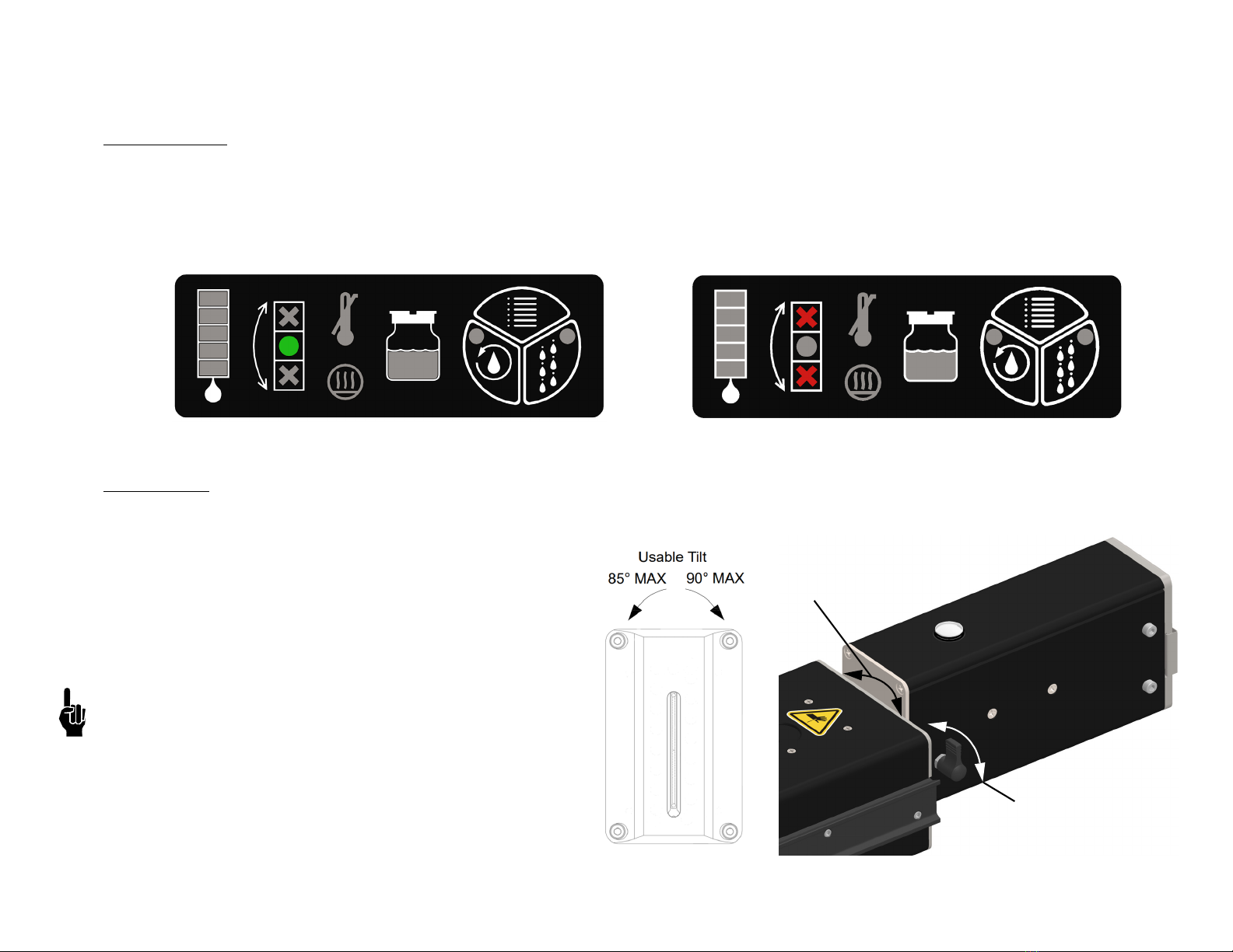
Step 8: Printer Level and Tilt
Printer Level
1. Slightly loosen the Slide Bracketry Screws shown in the diagram in "Step 7: Adjust Printer to Substrate" on page 15.
2. When the Printer is perpendicular to the substrate, tighten the Slide Bracketry Screws.
3. Observe the LED indicators on the rear top of the Printer on the ink supply. The green LED should be illuminated, and if not, adjust the
bracketry up or down as needed.
4. The Printer is calibrated to within +/-1.5°
Printer Tilt
1. Loosen the tool-less handle on the side of the Printer Module.
2. Rotate the Printer Module to an angle that creates
perpendicular print on the product.
3. Tighten the tool-less handle.
Maximum Printer Tilt from Vertical When Viewed from
the Rear of the Printer:
• Clockwise Tilt: 85° (Printer Module disengages from the
Ink Supply Module at 90°)
• Counterclockwise Tilt: 90°
Cleaning and priming features are effective up to ±15°
Printer Level Printer Not Level
Tool-less
Locking Handle
Rotate PM to
Adjust Tilt
Piezo InkJet System Section 2: Quick Start
400386UB Operations Manual Rev A Page 17
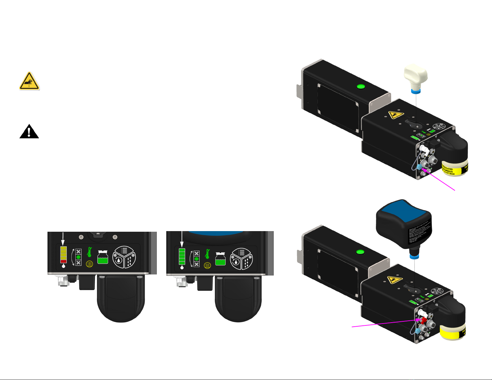
Step 9: Install Ink Cartridge
1. Remove the shipping plugs from the rear and top of the Ink Supply Module.
Retain plugs for potential later use.
2. Install the ink cartridge and vent filter as shown.
Warning! Opening the cartridge door exposes sharp needles used to
puncture the cartridge rubber seal. Extreme caution should be used during
the cartridge insertion.
3. Install the cartridge in the orientation shown with safety information label
facing towards the rear of the Printer.
Note: The cartridge is equipped with smart chip technology that will detect the
presence of the cartridge. The cartridge can only be installed in one orientation as
it is keyed to the Ink Supply receiver which will guarantee connection to the smart
chip.
When the cartridge is installed, the state of the ink gauge LED indicators on the
top of the Ink Supply and the LED on the top of the Printer Module will change
from flashing to solid green as shown below.
For a full description of the LED / Button panel on the top of the of Ink Supply
Module see "Ink States" on page 40.
Ink Cartridge
Shipping Plug
Vent Plug
Vent Filter
Ink Cartridge
INSTALL
REMOVE
Flashing Solid

Piezo InkJet System Section 2: Quick Start
400386UB Operations Manual Rev A Page 18
Step 10: Priming the Printer and Testing Print Quality
1. Ensure all Printers are at operating temperature.
2. Ensure that the shipping cap is installed for Recirculation, otherwise ink may overflow.
NOTE: Print is disabled until the Printer is fully heated. Wait until the "AT-TEMPERATURE”
LED is illuminated green on the rear of the Printer prior to any print sampling.
3. Press and hold the Recirculation button (10 seconds) on the rear top of the ISM until its
LED turns on. The ink gauge will count up during this time.
4. Allow the Printer to recirculate for at least 2 minutes. To turn off the recirculation feature,
press the Recirculation button once, and the LED will turn off.
5. Wait three seconds and remove the ship cap.
6. Press and hold the Clean / Prime button for 5 seconds.
7. Reinstall the shipping cap and run Recirculation again for 15 minutes. After 15 minutes,
the recirculation feature will automatically turn off.
8. Remove the shipping cap, and store on the top of the Printer.
NOTE: Do not use common wipes in the print channel; use foam swabs instead.
9. Use a foam swab to lightly wipe the orifice plate in a vertical downward motion. Prime
the Printer by pressing and holding the Clean / Prime button up to 5 seconds (Prime).
The Clean / Prime button LED will illuminate during this time and print will be disabled.
After an additional 15 seconds, the LED will turn off and print will be re-enabled.
10. Print can be tested by slowly passing a sheet of paper in front of the Printer after pressing
the All Channel Print button. A solid image will print for approximately 3 seconds.
11. If the 2" Printer sample is 50,8 mm (2 in) tall with no gaps, the Printer is ready.
If the 4" Printer sample is 101,6 mm (4 in) tall with no gaps, the Printer is ready.
Missing Print
1. Press and hold the Clean / Prime button for five (5) seconds (Prime).
2. Inspect for very small air bubbles flowing out of the top of the orifice plate. If bubbles are
evident, repeat the previous step one more time.
3. Press the All Channel Print button.
4. If any print is still missing after all air bubbles are purged, repeat steps 7. - 9., in "Step 10:
Priming the Printer and Testing Print Quality" on page 18, up to three more times as
necessary.
CLEAN / PRIME
BUTTON
ALL CHANNEL
PRINT BUTTON
AT TEMPERATURE LIGHT
GREEN - AT TEMP
RED - NOT AT TEMP
RECIRCULATION
BUTTON
RECIRCULATION
LED
HEATER ON RECIRCULATION
BUTTON
SHIP CAP INSTALLED
SWAB
DOWN
SHIPPING CAP STORAGE
CLEAN / PRIME
LED

Piezo InkJet System Section 2: Quick Start
400386UB Operations Manual Rev A Page 19
Step 11: Cap Unused Ports
After the installation is complete, it is recommended that all unused ports be capped to prevent accidental electrostatic discharge into
a connector.
Step 12: Create a Message and Control the Printer
Reference manual Create & Control 400463.
PHOTOSENSOR
ETHERNET TO
DOWNSTREAM
PRINTER OR
HMI
24VDC
POWER
ENCODER
USB DEVICE OR
FIRMWARE UPGRADE
(HAS BUILT-IN CAP)
ETHERNET FROM
UPSTREAM PRINTER OR
CUSTOMER NETWORK
The Primary Printer should have all ports populated with a
cable.
Exceptions:
• Only one head in the daisy chain - cap Ethernet and one
power port.
• No encoder - cap encoder port.
• Wireless communication - cap Ethernet ports.
• No HMI - cap Ethernet port.
Secondary Printers will have most ports capped excluding
one power port.
Exceptions:
• Wired Ethernet port - cap other Ethernet port.
• Second power port is connected to HMI.
See "Service Parts and Optional Equipment" on page 49 for
plug and cap kits.

Piezo InkJet System Section 3: Maintenance and Shutdowns
400386UB Operations Manual Rev A Page 20
Section 3: Maintenance and Shutdowns
Following are the recommended maintenance procedures to keep the Printer printing cleanly and efficiently.
System Maintenance
Intermittent (as required):
1. Be sure the photosensor is clean and free of debris.
2. Be sure the nuts and bolts holding the bracketry in place remain tight.
3. Ensure all cable connections are secure but not overtightened.
4. Adjust Printer Module level and throw distance as necessary.
Annually:
Clean the encoder and review the wheel for excess wear.
Printer Module Maintenance
Daily / Shift Startup / Periodic
Wear safety goggles when working with industrial inks or solutions!
The majority of print quality degradation is due to excessive debris deposits on the
Printer orifice plate that disrupt the ink droplet path. For best preventative
maintenance practices, do the following:
1. Remove excessive debris build-up (corrugate dust, glue strands, and the like) on and
around the front of the Printer by using maintenance spray (5760695) on a clean lint-free
cloth (6600171) and wiping the front plate and enclosure. If debris build-up is noted on
the enclosure and rear of the Printer, then wipe those clean too.
NOTE: DO NOT SPRAY MAINTENANCE SPRAY DIRECTLY ON THE PRINTER MODULE OR ANYWHERE NEAR THE ORIFICE PLATE.
2. Press and release the Clean / Prime button (Clean), and using a sponge swab (5760832), rub the orifice plate lightly from top down in a
vertical direction while ink is flowing during a clean cycle. The Clean / Prime button is located on the rear of the Printer. DO NOT USE n-
Propanol directly on the orifice plate.
3. Press the Clean / Prime button one more time (Clean) to ensure channel priming, but do not swab this time.
4. Wipe the front plate with a clean lint-free cloth to remove any excess ink.
SWAB
DOWN
SHIPPING CAP STORAGE
CLEAN / PRIME BUTTON
Table of contents
Other Illinois Tool Works Industrial Equipment manuals


