Illinois Tool Works ResMark 5000 User manual
Operations
Manual
1 Missouri Research Park Drive • St. Charles, MO 63304 • Service Line 1-800-526-2531
Illinois Tool Works Inc © 2021
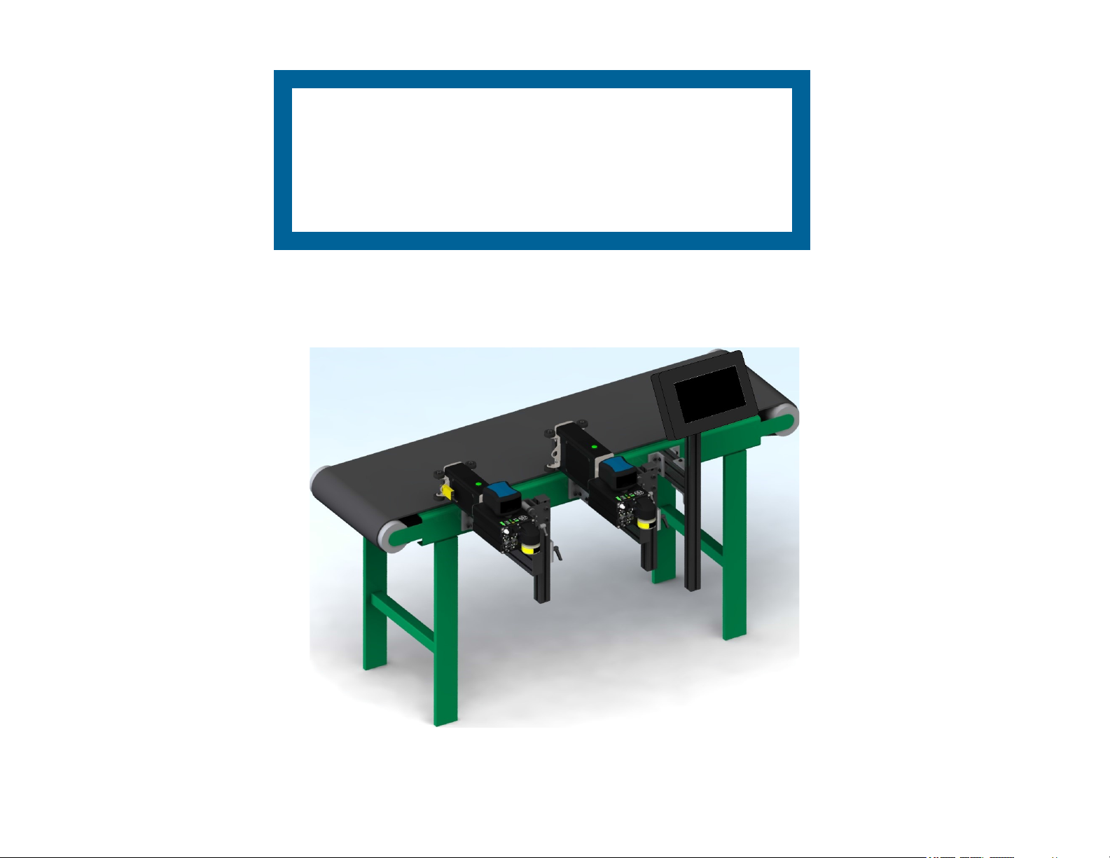
ResMark 5000 High-Resolution System
400386
Revision A

ResMark 5000 High-Resolution
Ink Jet System
Operations Manual
400386
The information contained in this manual
is correct and accurate at the time of its
publication. ITW reserves the right to
change or alter any information or
technical specifications at any time and
without notice.
©2022 Illinois Tool Works Inc.
All rights reserved

The ResMark 5000 High-Resolution System, including all components unless otherwise specified, carries a limited
warranty.
The inks and conditioners used with the ResMark 5000 High-Resolution System carry a limited warranty.
For all warranty terms and conditions, contact Diagraph, an ITW Company, for a complete copy of the Limited Warranty
Statement or visit Diagraph.com.
Warranty:
ResMark 5000 System

Section 1: Safety and Ink Usage ..........................................................................................................................................................................6
Section 2: Quick Start ...........................................................................................................................................................................................7
Step 1: Assemble Bracketry to Conveyor ...................................................................................................................................................8
Step 2: Assemble Print Head onto Bracketry .............................................................................................................................................9
Step 3: Mount and Connect Power Supply ...............................................................................................................................................10
Step 4: Powering up the Print Heads ........................................................................................................................................................11
Step 5: Adjust Print Head to Substrate .....................................................................................................................................................12
Step 6: Print Head Level and Tilt .............................................................................................................................................................13
Step 7: Install Ink Cartridge ......................................................................................................................................................................14
Step 8: Priming the Print Head and Testing Print Quality ........................................................................................................................15
Step 9: Mount Photosensor and Encoder ..................................................................................................................................................16
Step 10: Daisy-Chain Print Heads, HMI, and/or Customer Network .......................................................................................................17
Step 11: Cap Unused Ports .......................................................................................................................................................................19
Step 12: Create a Message and Control the Print System .........................................................................................................................19
Section 3: Maintenance and Shutdowns ...........................................................................................................................................................20
System Maintenance .................................................................................................................................................................................20
Printer Module Maintenance ....................................................................................................................................................................20
Ink Supply Module Maintenance ..............................................................................................................................................................21
Printer System Shutdown ..........................................................................................................................................................................21
Cleaning Maintenance System ..................................................................................................................................................................22
Printer Module Replacement ....................................................................................................................................................................23
Section 4: Troubleshooting ................................................................................................................................................................................24
Print Quality ..............................................................................................................................................................................................24
System .......................................................................................................................................................................................................27
Appendix A: System Specifications ...................................................................................................................................................................30
System .......................................................................................................................................................................................................30
Touch Pro 2 HMI ......................................................................................................................................................................................31
Mark 2 Print Head .....................................................................................................................................................................................32
Mark 4 Print Head .....................................................................................................................................................................................33
System Interconnect Diagram ...................................................................................................................................................................34
Customer System Connection ...................................................................................................................................................................35

Appendix B: Theory of Operation ....................................................................................................................................................................36
Functional Description ..............................................................................................................................................................................36
ResMark 5000 Mark 2 and Mark 4 Print System .....................................................................................................................................36
ISM Features .............................................................................................................................................................................................37
Ink States ...................................................................................................................................................................................................38
Print Head Daisy Chain ............................................................................................................................................................................39
Print Trigger Photosensor .........................................................................................................................................................................39
Encoder .....................................................................................................................................................................................................39
Appendix C: Diagrams .......................................................................................................................................................................................40
ResMark 5000 Main CPU PCB Assembly ...............................................................................................................................................40
ResMark 5000 Internal Wiring Diagram ..................................................................................................................................................41
Appendix D: Ink ..................................................................................................................................................................................................42
Storage Life of a FACTORY SEALED Bottle of Ink ..............................................................................................................................42
Use Life of an OPENED Cartridge of Ink ................................................................................................................................................42
Appendix E: Updating the ISM via USB or Ethernet .....................................................................................................................................42
Appendix F: Software Interface ........................................................................................................................................................................42
Appendix G: Part Numbers ...............................................................................................................................................................................43
System .......................................................................................................................................................................................................43
Print Head Replacement Parts ..................................................................................................................................................................44
Bracketry ...................................................................................................................................................................................................45
Fittings ......................................................................................................................................................................................................46
Cables ........................................................................................................................................................................................................46
Service Parts and Optional Equipment .....................................................................................................................................................47
Other manuals for ResMark 5000
1
Table of contents
Other Illinois Tool Works Industrial Equipment manuals


