Ilsintech SWIFT F1 User manual

Body Appearance & How to use Keypad
Swift F1
Quick Reference Guide
Cleaner
Auto Stripper Sleeve Heater
Cleaver with Fiber Chip Collector
Splicer
Power Button
LCD Monitor
Reset / Return Button
Wind Protector
Cursor Buttons
Enter & Menu Button
Auto Stripper Button
(Start Heating)
Arc Button
(Start Splicing)
Sleeve Heater Button
(Start Heating)
Battery Pack
Battery Indicator Button
Remaining Battery Indicator LED
USB Port
Esc Button
Power Supply
Power Requirements
•A
C
po
w
e
r
supp
l
y
f
o
r
t
h
e
spec
ifi
ed
Charging the Battery
•When charging, LED light blinks Red→
Green→Yellow.
•Full charging the batteries take
approx. 2 hours.
•Power Indicator LED
LED light turns:
DC
-
DC Adaptor (Option)
Battery
Pack
F1-2
Charger
AC-DC
Adaptor
AC Code
Battery Capacity Check
•Remaining battery capacity is
displayed on both the top right
corner of the Monitor and the
AC
power
supply
for
the
specified
charger is AC 100-240V, 50-60Hz.
•Do not use AC power other than
the allowable power indicated.
•Do not use a battery charger other
than the specified charger provided
with product.
•The LED light turns Red→Green→
No Light (F1-2 Charger).
•Auto shutoff devices are built in the
batteries to prevent over arc, over
charge and overload.
When these protection functions
Red→Green→Yellow
DC
DC
Adaptor
(Option)
•Connect the DC cord of the charger to
Adaptor.
•DC adaptor charged while operating
and plugged.
•Only one Plug-in (Right Side Adapter)
DC-DC
Adaptor
battery indicator LED
Contact : Contact : [email protected][email protected] / +82/ +82--4242--671671--5609~115609~11
are performed, power is automatically
shutoff.

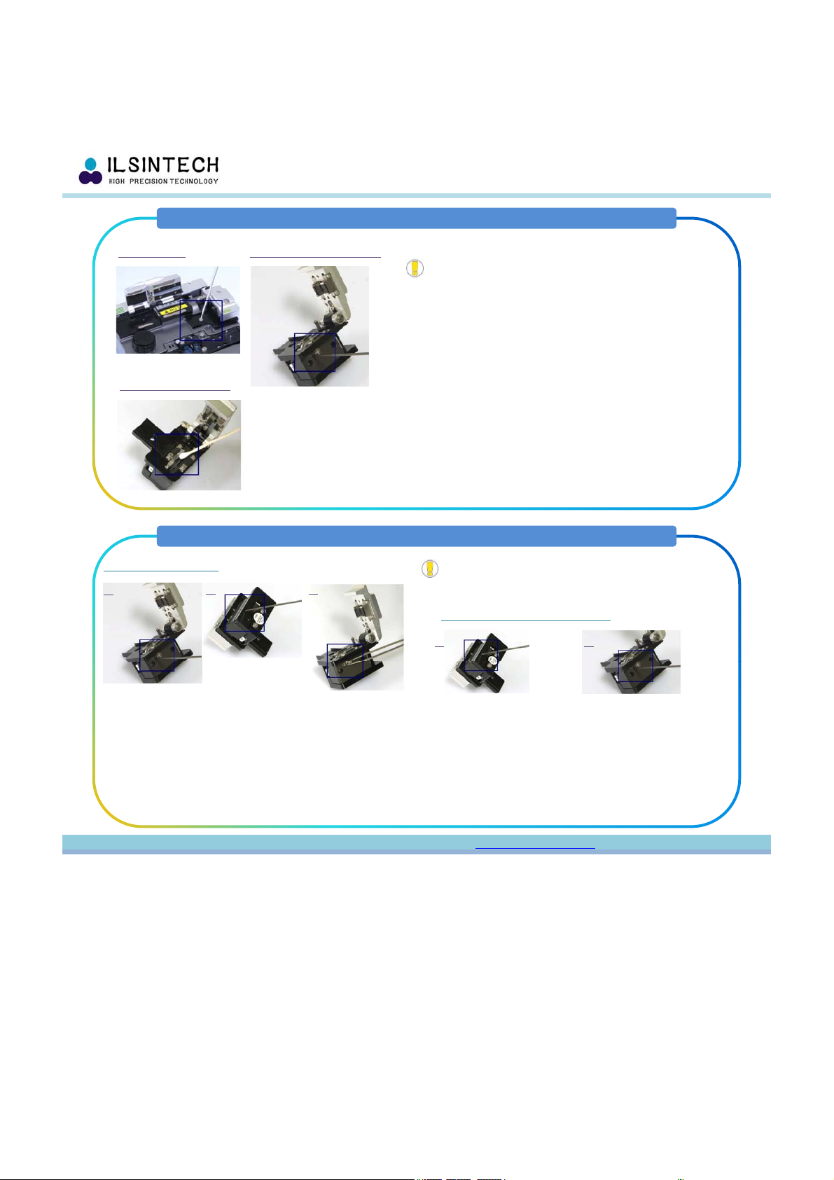
Cleaning & Inspection
Swift F1
Quick Reference Guide
•Brush the surface of the V-grooves & Stripper and clean
with a cotton swab moistened with alcohol.
•Remove the remaining alcohol in the V-grooves with a dry
clean cotton swab.
•Use the cleaved optical fiber to remove contaminants
from the V-grooves if any remain.
•
Clean the surface of the wind protector prisms with a lens
Clean the V-Groove Clean the Stripper
•
Turn OFF the F1 before Cleaning & Inspection.
•
Be careful handling the ELECTRODES.
•
Brush the V-Groove & Stripper frequently before / after using F1.
•
Be careful handling STRIPPER BLADE PART which is very sensitive.
Clean
the
surface
of
the
wind
protector
prisms
with
a
lens
cleaner or cotton swab.
•Remove the electrodes before cleaning the object lenses.
•Clean the surface of the lens(X axis & Y axis) softly with
a lens cleaner or cotton swab.
•Remove remaining alcohol with a dry clean cotton swab.
•Turn on the power and check the clarity of the lens into
the display LCD monitor.
Press the “▽” cursor button to change the screen and inspect
the surface of the lens.
Wind Protector Prism Clean the Object Lens
Routine Maintenance
Re
p
lacin
g
Electrode
s
•
Turn OFF the F1 before doing process.
•
Be careful handling the ELECTRODES.
•
Brush the V-Groove &Stripper frequently before / after using F1.
•
Cleaning Electrodes once every 500 times arc with a cotton swab
moistened with alcohol.
1
Fthi ltAUX
Battery Maintenance
•Discharge the battery completely
at least once every 3 months in
order to avoid memory effect.
•Storage temperature should be
between -20℃ and 30℃.
•
Recharge the battery every 6
pg
1
.
F
rom
th
e ma
i
n menu, se
l
ec
t
AUX
menu, press
ENTER, REPLACE ELECTRODES, and press ENTER.
2. Loosen the thumb-screws and remove the electrodes.
3. Clean the new electrodes and install.
4. From the main menu, perform the ARC Calibration.
Select AUX menu, perform the Stabilize Electrode
in order to stabilize electrodes.
5. From the main menu, select AUX menu, set the “O”
arc count through the Clear ARC Count
•
Recharge
the
battery
every
6
months when not in use.
Routine Diagnostics
The following tests are found in
the OTHER menu in the system
menu, and should be performed
once every 3 months.
•Dust Check
•Motor Drive
•
LED Check
Contact : Contact : [email protected][email protected] / +82/ +82--4242--671671--5609~115609~11
arc
count
through
the
Clear
ARC
Count
LED
Check
Change of Blade Channel (Cleaver)
Swift F1
Quick Reference Guide
1. Detach the automatic cleaver (Swift CI-03) from the F1
body using a hexagon wrench as shown the picture 1.
2. Open the cover and push the slider forward.
When the slider is fixed, loosen the set screw a little
bi ( 2 ) i h h h
1. Detaching 2. Loosing the set screw
•
Turn OFF the F1 before doing process.
•
Be careful handing the Blade.
bi
t
(
approx.
2
turns
)
w
i
t
h
a
h
exagon wrenc
h
.
3. Turn the marking on the blade counter-clockwise one
by one with a cotton swab.
Assemble the automatic cleaver in the reverse manner of
detaching.
3. Changing Channel
Blade Replacement & Adjustment of Blade Height (Cleaver)
Blade Replacement
•
Turn OFF the F1 before doing process.
•
Be careful handling the Blade.
•
Thoroughly & Accurately set the height using a gauge
because the height directly effect SPLICE LOSS.
1.
2. 3.
Adjustment of Blade Height
2.
1.
1. Loosen the set screw at the side of the cleaver detached
from the F1 a little bit (approx. 2 turns) with a wrench.
2. Insert a wrench into the hole at the bottom of the cleaver
and loosen the set screw of the slider a little bit
(approx. 2 turns). Slider has to be moved backward.
3. Insert the wrench bolt into the cam pin and pull it with
tweezers and detach the slider.
4. Not to damage the blade. Assemble the part in the
1. Insert a wrench into the hole at the bottom of the cleaver
and loosen the set screw of the slider a little bit
(approx. 2 turns). The slider has to be moved backward.
2. Adjust the blade height by turning Cam Pin.
Clockwise turning: HEADING to UPWARD
Counter-Clockwise turning: HEADING to DOWNWARD
3. When the blade reaches required position, tighten the set
screw of the slider.
Contact : Contact : [email protected][email protected] / +82/ +82--4242--671671--5609~115609~11
reverse manner.

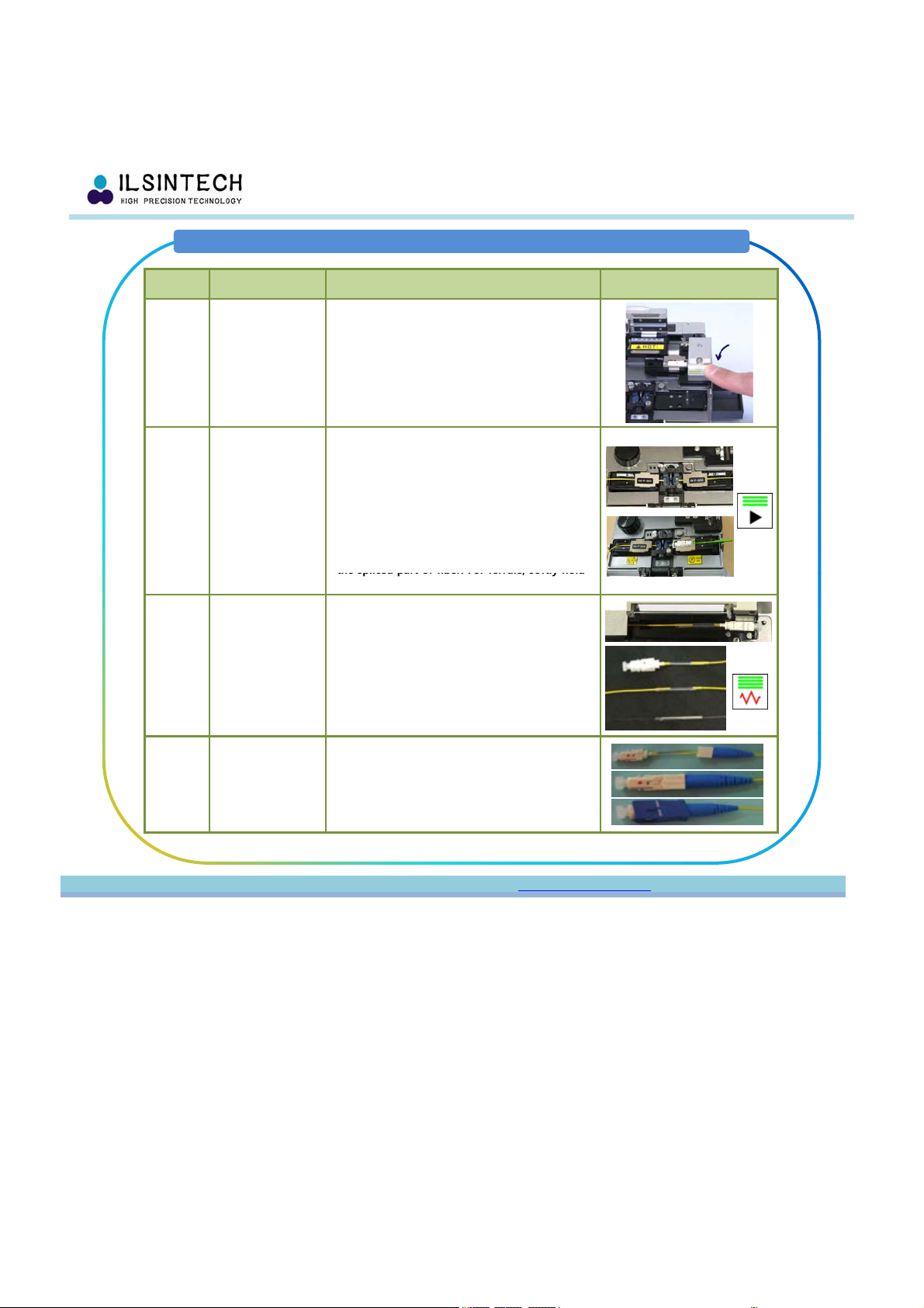
Splicing Operation
Swift F1
Quick Reference Guide
Step Description Procedure
1Turn the F1 on
Press and The POWER button 1 time.
Home screen will be displayed when all motors
are reset to their initial positions.
Select a proper splice mode for exact splicing.
The current splice mode is displayed in the
2Select Splice
Mode
and Heater Mode
The
current
splice
mode
is
displayed
in
the
home screen.
Select heater mode.
The current heater mode is displayed on the
home screen.
3
Inserting Sleeve
Tube &
Connector Boot
Installing Holder
Insert the sleeve tube and boot part (when
splice fiber to connector) into the fiber.
FOR FERRULE, TAKE OFF THE ORIGINAL CAP,
THAN INSERT THE FERRULE CAP.
Install the fiber or ferrule into the proper fiber
holder.
(250㎛, 900㎛, 2.5㎛, and Ferrule t
yp
e holders)
Sleeve Tube Fiber
Ferrule Ferrule Cap
yp
4Stripping
Operation
Warm up stripper heater. First close holder
part cover after mounting the fiber holder
onto the Auto stripper. SECOND, SLAM THE
HEATER PART COVER IN ORDER TO FIRMLY
STRIP COATING WITH BLADES. The fiber is
heated up and the coating is automatically
stripped by moving the slide. When process is
completed, FIRST SOFTLY OPEN HOLDER PART
COVER, AND DETACH FIBER HOLDER. Open
heater part cover, remove remaining coating
and brush for next operation. CAREFULLY
HANDLING BLADE PARTS FOR STRIPPING
HANDLING
BLADE
PARTS
.
FOR
STRIPPING
TEMPERATURE BETTER SET BETWEEN 75℃ to
80℃.
5Cleaning
Operation
Discharge alcohol by pressing 2 or 3 times with
a cleaning wipe by hand. BE CAREFUL NOT TO
WET THE EQUIPMENT.
Contact : Contact : [email protected][email protected] / +82/ +82--4242--671671--5609~115609~11
Splicing Operation
Swift F1
Quick Reference Guide
Step Description Procedure
6Cleaving
Operation
Automatic clever(CI-03) cleaves SM & MM
fibers at right angle. Open cleaver cover and
mount stripped and cleaned fiber holder into
the cleaving position. CHECK THE FIBER IS
PROPERLY LYING IN PLACE. Open chip-box
located at the right side of the F1. WHEN
CLEAVE FIBER, FIRMLY PUSH CLEAVE COVER.
After cleaving BE CAREFUL THE FIBER FROM
ANY DUST OR CONTAMINANT
ANY
DUST
OR
CONTAMINANT
.
7Splicing
Operation
Mount cleaved fiber holders into both sides of
the splicer between the V-grooves and
electrodes. CHECK THE FIBERS ARE PROPERLY
PLACED ON THE V-GROOVES. Gently close the
wind protector. Press the ARC button to begin
splicing. REDUCING SPLICE LOSS FIBERS MUST
BE PLACED ON CORRECT POSITIONS AND BE
CAREFUL THE FIBER FROM ANY DUST OR
CONTAMINANT. Dispatch fibers from the
holders, and gently move the sleeve tube to
the spliced part of fiber. For ferrule, softly hold
the
spliced
part
of
fiber.
For
ferrule,
softly
hold
its cap and take out from fiber holders.
8Sleeve Heater
Operation
Open heater cover and set the fiber into the
inside of heater. FOR FERRULE, RED MAKE
MUST BE HEADING TO USER’S CHEST AND
MUST BE SET TO THE RIGHT-MOST POSITION
OF HEATER. Press sleeve heater button in order
to active. Cooling fan is run to cool the sleeve
tube after 20 sec when completed the heating
process. Open the heater cover when cooling is
completed and take out the reinforced fiber.
9Assembling
Connector
Operation
Take off ferrule cap and assemble it with boot
part. Assemble ferrule , jointed with boot part,
with grip part.
Contact : Contact : [email protected][email protected] / +82/ +82--4242--671671--5609~115609~11

THE Choice of a Lever Block by Cable & Connector Type
Swift F1
Quick Reference Guide
Heater Block R
Type Description Type Description
•SC / FC Connector
•LC Connector
•0.25 / 0.9mm Fiber
•2.0 / 2.4mm Cable
•
2.0mm Cable
Set Screw
2.0mm
Cable
•Indoor Cable
Lever Block
Heater Block L Heater Block R
Type Description Type Description
•0.25 / 0.9mm Fiber •0.25 / 0.9mm Fiber
•2.0 / 2.4mm Cable
•LC Connector
•2.0 / 2.4mm Cable
•
30mm
Cable
•
30mmCable
•
3
.
0mm
Cable
•
3
.
0mm
Cable
•Indoor Cable •Indoor Cable
Standard Package: Heater Block R (2EA), Lever Block (1PAIR)
O
p
tional Packa
g
e: Lever Block
(
3PAIR
)
Contact : Contact : [email protected][email protected] / +82/ +82--4242--671671--5609~115609~11
pg ()

THE Choice of a Lever Block by Cable & Connector Type
Swift F1
Quick Reference Guide
Sleeving 0.9mm Fiber with SC Connector
Step Description Procedure
1•Loosen the Set Screw on Heater Block L
2•Mount “1” Lever Block
•Tighten the Set Screw
3•Loosen the Screw on Bottom of Heater Block R
4•Replace the Heater Block R for SC/FC Connector
•Tighten the Screw
5•Placed on the 0.9mm Fiber & SC Connector on the
Sleeve Heater
6•Complete
Contact : Contact : [email protected][email protected] / +82/ +82--4242--671671--5609~115609~11

THE Choice of a Lever Block by Cable & Connector Type
Swift F1
Quick Reference Guide
Sleeving 3.0mm Cable with SC Connector
Step Description Procedure
1•Loosen the Set Screw on Heater Block L
2•Mount “3” Lever Block
•Tighten the Set Screw
3•Loosen the Screw on Bottom of Heater Block R
4•Replace the Heater Block R for SC/FC Connector
•Tighten the Screw
5•Placed on the 3.0mm Cables on the Sleeve Heater
6•Complete
Contact : Contact : [email protected][email protected] / +82/ +82--4242--671671--5609~115609~11
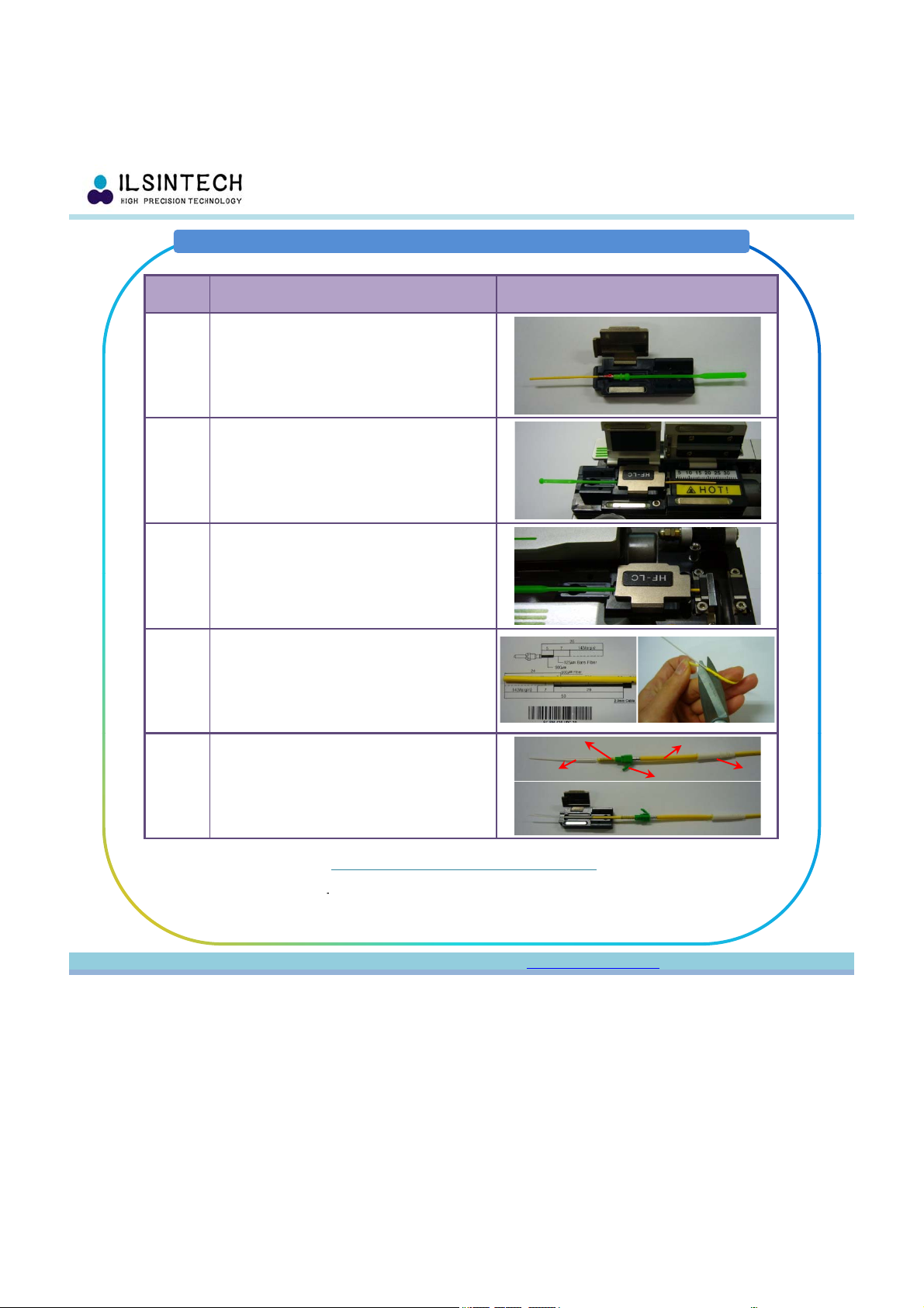
Swift LC Connector Assembly Procedure (2.0mm)
Swift F1
Quick Reference Guide
Step Description Procedure
1•Place Ferrule Part on HF-LC Holder
2•Ferrule Part Stripping
3
Fl
PtCl i
3
•
F
erru
l
e
P
ar
t
Cl
eav
i
ng
4•Stripe 2.0mm Cable PVC Outer Sheath.
•Cut Kevlar.
5•Insert Boot, Heat Shrinkable Tube, Stopper,
Spring and Sleeve into the 2.0mm Cable.
•Place 2.0mm Cable on HF-2.5 Holder
Sleeve use environmental condition
-Tem
p
.: 160℃
Boot
Heat Shrinkable Tube
Stopper
Spring
Sleeve
Contact : Contact : [email protected][email protected] / +82/ +82--4242--671671--5609~115609~11
p
- Operating Time: 20sec
※ The most recommended Operating Time: 30sec ※

Swift LC Connector Assembly Procedure (2.0mm)
Swift F1
Quick Reference Guide
Step Description Procedure
6•2.0mm Cable Stripping & Cleaving
7•Splicing
8
•Sleeve 1 – Heating Sleeve
8
(Placed on Sleeve on Heater as PIC)
9
Splicing & Stopper Assembly
(APC Connector – Red Mark in the APC Ferrule
must head to the upward, then assembly to the
Plug Frame)
10 •Sleeve 2 – Heating Heat Shrinkable Tube
(Placed on Tube on Heater as PIC)
11
•
Complete
Contact : Contact : [email protected][email protected] / +82/ +82--4242--671671--5609~115609~11
11
Complete

2.0~3.0mm Indoor Cable Connector Assembly Process
Swift F1
Quick Reference Guide
Step Description Procedure
1Place 2.0~3.0mm Cable on Holder
Cutting Kevlar point
2Cut Kevlar
Approx. 20mm
3Heat Shrink the Sleeve
Sleeve
Kevlar inside of Sleeve
Contact : Contact : [email protected][email protected] / +82/ +82--4242--671671--5609~115609~11

2.0~3.0mm Indoor Cable Connector Assembly Process
Swift F1
Quick Reference Guide
Step Description Procedure
4Assemble Boot
5Assemble Housing & Clamp Cap
Boot
Clamp Cap
6Complete
Housing
Contact : Contact : [email protected][email protected] / +82/ +82--4242--671671--5609~115609~11

Error Messages
Swift F1
Quick Reference Guide
Symptom Cause Solution
Clad
Deviation Dust in V-Groove or
the chip of core wire
guide.
Cleaning V-Groove
or the chip of core
wire guide.
Clad An
g
le
Dust in V-Groove or
the chip of core wire
g
uide.
Cleaning V-Groove
or the chip of core
wire
g
uide.
Symptom Cause Solution
Bubble
Bad condition of the
cross section of
fiber.
Checking whether
fiber cleaver is
working properly.
Too low amount or
short time of initial
arc discharge.
Increase the amount
and/or time of initial
are discharge.
g
g
g
Bad condition of the
cross section of fiber.
Checking whether
fiber cleaver is
working properly.
Clad
Deformation
Bad condition of the
cross section of fiber.
Checking whether
fiber cleaver is
working properly.
Too low amount or
short time of initial
arc discharge
Increasing the
amount and time of
initial arc discharge.
Ch ki
hth
Separation Too high amount or
long time of initial
arc discharge.
Increase overlapping.
Decreasing the
amount and/or time
of initial arc
discharge.
Thick Too long fiber
length.
Reducing the length
of duplicated area.
Clad Flexion
Bad condition of the
cross section of fiber.
Ch
ec
ki
ng w
h
e
th
er
fiber cleaver is
working properly.
Too low amount or
short time of initial
arc discharge.
Increase the amount
and time of initial
arc discharge.
Burning
Bad condition of the
cross section of
fiber.
Checking whether
fiber cleaver is
working properly.
Dust still remaining
after
cleaning the
Cleaning carefully
the fiber or
Thin
Improper discharge
amount.
Conducting
discharge amount
calibration
A few improper
discharge factors.
Adjusting initial
discharge amount,
initial discharge time
and overlapped area.
Line Several number of
im
p
ro
p
er dischar
g
e
Adjusting initial
discharge amount,
initial discharge time
after
cleaning
the
fiber or conducting
cleaning discharge.
the
fiber
or
increasing the arc
discharge time.
pp g
factors.
initial
discharge
time
and overlapped area.
Contact ILSINTECH
Add:
#703 Gwanpyeong-dong Yusung-gu
Daejeon
305
-
509 Korea
Contact : Contact : [email protected][email protected] / +82/ +82--4242--671671--5609~115609~11
Daejeon
305
509
,
Korea
Tel:
+82-42-671-5609~11
Fax:
+82-42-671-5612
E-mail:
www.ilsintech.com
Other manuals for SWIFT F1
1
Table of contents
Popular Industrial Equipment manuals by other brands


Kooltronic
Kooltronic KNHX32 Series Operator's manual

ABB
ABB HT611730 Operation manual

Rockwell Automation
Rockwell Automation Allen-Bradley LDAT Series installation instructions

ABB
ABB HT581629 Operation manual

DALIN
DALIN DLVC Installation, operation and maintenance

schmersal
schmersal AZM201B-I2-SK-T-1P2PW-A instructions

GREEN INSTRUMENTS
GREEN INSTRUMENTS G3610 instruction manual

matev
matev CLS-SE operating manual

Donaldson Torit
Donaldson Torit RWB-2000 Installation and operation manual

Premier
Premier 370PK Service guidelines

Rath
Rath RGD Series Installation & operating manual

Martin
Martin Tornado installation instructions