Iluminarc LOGIC AR111 DN M User manual

Model ID: LOGICAR111DNM
Quick Reference Guide
English EN
Español ES
Français FR
Deutsch DE
Nederlands NL

1
EN
QUICK REFERENCE GUIDE
LOGIC AR111 DN M QRG Rev. 4
About This Guide
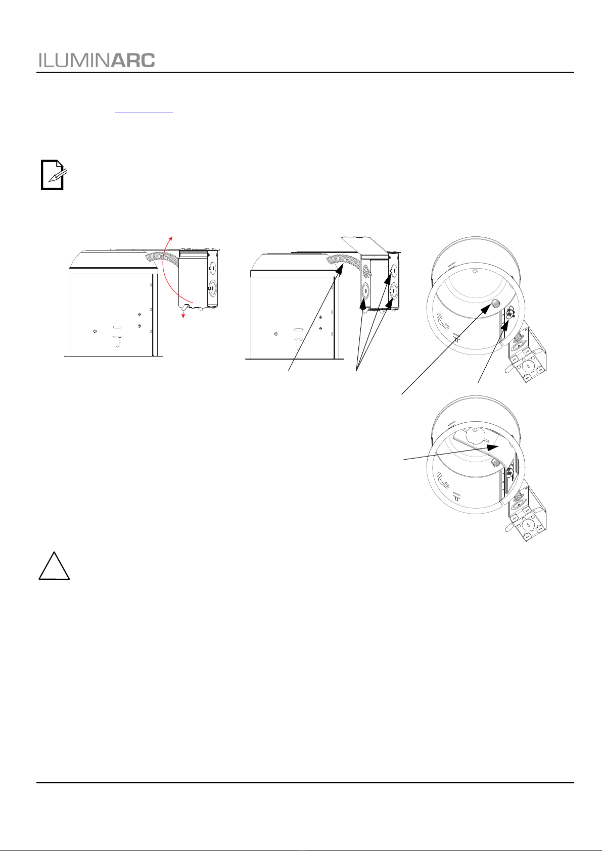
The LOGIC AR111 DN M Quick Reference Guide (QRG) has basic product information such as mounting, menu options,
and DMX values. Download the User Manual for the LOGIC DRIVE 2X from www.iluminarc.com for more details.
Disclaimer
The information and specifications contained in this QRG are subject to change without notice.
LIMITED WARRANTY
FOR WARRANTY REGISTRATION AND COMPLETE TERMS AND CONDITIONS PLEASE VISIT OUR WEBSITE.
For Customers in the United States and Mexico: www.www.iluminarc.com/warranty-registration-architectural-lighting.
For Customers in the United Kingdom, Republic of Ireland, Belgium, the Netherlands, Luxembourg, France, and
Germany: www.www.iluminarc.com/warranty-registration-architectural-lighting.
Chauvet warrants that this product shall be free from defects in material and workmanship under normal use, for the
period specified in, and subject to the exclusions and limitations set forth in the full limited warranty on our website. This
warranty extends only to the original purchaser of the product and is not transferable. To exercise rights under this
warranty, you must provide proof of purchase in the form of an original sales receipt from an authorized dealer that shows
the product name and date of purchase. THERE ARE NO OTHER EXPRESS OR IMPLIED WARRANTIES. This
warranty gives you specific legal rights. You may also have other rights that vary from state to state and country to
country. This warranty is valid only in the United States, United Kingdom, Republic of Ireland, Belgium, the Netherlands,
Luxembourg, France, Germany and Mexico. For warranty terms in other countries, please consult your local distributor.
Safety Notes
These Safety Notes include important information about installation, use, and maintenance.
• The luminaire should be positioned so that prolonged staring into the luminaire at a distance closer than 3.3 ft (1m)
is not expected.
• If the external flexible cable or cord of this luminaire is damaged, it shall be replaced with a special cable or cord
exclusively available from the manufacturer or its service agent.
• The light source contained in this luminaire shall only be replaced by the manufacturer, its service agent, or a
similarly qualified person.
• The luminaire is intended for professional use only.
• DO NOT open this product. It contains no user-serviceable parts.
• DO NOT look at the light source when the product is on.
• CAUTION: When transferring product from extreme temperature environments, (e.g. cold truck to warm humid
ballroom) condensation may form on the internal electronics of the product. To avoid causing a failure, allow
product to fully acclimate to the surrounding environment before connecting it to power.
• CAUTION: This product’s housing may be hot when lights are operating.
• Mount this product in a location with adequate ventilation, at least 20 in (50 cm) from adjacent surfaces.
• DO NOT leave any flammable material within 11.8 in (30 cm) of this product while operating or connected to power.
• USE a safety cable when mounting this product overhead.
• DO NOT operate this product outdoors or in any location where dust, excessive heat, water, or humidity may affect
it. (IP20)
• DO NOT operate this product if the housing, lenses, or cables appear damaged.
• ONLY connect this product to IEEE 802.3bt POE power source equipment (PSE).
• ONLY connect this product to a grounded and protected circuit.
• In the event of a serious operating problem, stop using immediately.
• The startup temperature range is -4 °F to 113 °F (-20 °C to 45 °C). Do not start the product outside this range.
• The operating temperature range is -40 °F to 113 °F (-40 °C to 45 °C). Do not operate the product outside this
range.
• The storage temperature range is -40 °F to 167 °F (-40 °C to 75 °C). Do not store the product outside this range.
FCC Compliance
This device complies with Part 15 Part B of the FCC Rules. Operations is subject to the following two conditions:
1. This device may not cause harmful interference, and
2. This device must accept any interference received, including interference that may cause undesired operation.
Any changes or modifications not expressly approved by the party responsible for compliance could void the user’s
authority to operate the equipment.
Contact
Outside the U.S., U.K., Ireland, Benelux, France, Germany, or Mexico, contact your distributor to request support or
return a product. Refer to Contact Us at the end of this QRG for contact information.
What is Included
• LOGIC AR111 DN M
• Medium and wide filters
• Hi-hat bracket
• Hanging pendant bracket
• Trim ring accessory
• Quick Reference Guide

EN
2
LOGIC AR111 DN M QRG Rev. 4
QUICK REFERENCE GUIDE
DC Power
This product is powered by the LOGIC DRIVE 2X with a CAT6 connection of 52 VDC. Download the User Manual for the
LOGIC DRIVE 2X from www.iluminarc.com for more details.
Power Linking
You can link up to 3 LOGIC AR111 DN M products from one output of the LOGIC DRIVE 2X.
Signal Linking
The LOGIC AR111 DN M will receive a control signal (DMX, RDM, Art-Net™, or sACN) from the LOGIC DRIVE 2X via a
CAT6 connection.
Connecting and Cabling
The LOGIC AR111 DN M has an IN port and an OUT port which require a CAT6 ethernet connection.
Short cables such as those run through the cable pipe of a hi-hat can may use a smaller gauge, but any cable longer than
50 ft (15 m) must be 23 AWG and shielded, or the products may not receive enough power.
Cable requirements: Max/Min gauge of 23/28 AWG CAT6 4 twisted pair.
• For distances less than 50 ft (15 m): 23-28 AWG (shielded or unshielded)
• For distances from 50-328 ft (15-100 m): 23 AWG (shielded)
Filters
The LOGIC AR111 DN M has 2 filter slots.
• The inner filter slot fits the medium filter (pre-installed) or the wide filter (included).
• The outer filter slot fits the LOGIC AR111 HF (Honeycomb Filter, sold separately by Iluminarc).
• To remove the installed filter, turn it until the keys on the edge line up with the openings in the slot.
• To install a filter in an empty slot, line up the keys on the edge with the openings in the slot and insert. Turn the
filter so the keys are secure.
The diameter of cable pipes in hi-hats requires a smaller diameter CAT6 cable, such as Monoprice
Slimrun CAT6 Ethernet patch cables, stranded 550 MHz, UTP, pure bare copper wire, 28 AWG.
Turn the filter no more than 60° or it may not be secure.
IN OUT
LOGIC DRIVE 2X
LOGIC AR111 DN M
Key (x3)
Medium or wide filter (inner slot) LOGIC AR111 HF (outer slot)
Key (x3)

EN
4
LOGIC AR111 DN M QRG Rev. 4
QUICK REFERENCE GUIDE
Hi-Hat Preparation
The LOGIC AR111 DN M comes with a hi-hat bracket for mounting in a hi-hat can. Before mounting this product in a hi-
hat can, read the Safety Notes.
1. Remove the AC power wiring from the junction box completely, and use a flat-head screwdriver or pliers to
remove a knockout for the CAT6 cables.
2. Route 2 unterminated CAT6 cables through the knockout and cable pipe and terminate them with RJ45 plugs on
the other end.
3. Remove the bracket which comes with the hi-hat, keeping any wingnuts for the next step.
4. Install the hi-hat bracket which came with the LOGIC AR111 DN M with the wingnut(s) from the previous step
This bracket is designed to replace the bracket which comes with the hi-hat.
The diameter of cable pipes in hi-hats requires a smaller diameter CAT6 cable, such as Monoprice
Slimrun CAT6 Ethernet patch cables, stranded 550 MHz, UTP, pure bare copper wire, 28 AWG.
Obey all local codes and regulations when installing hi-hats and wiring overhead.
Press down on the tab
to open the side panel
of the junction box
KnockoutsCable pipe
Pull CAT6 cables through
here and terminate with
RJ45 plugs
LOGIC AR111 DN M
hi-hat bracket
Wingnuts
!

5
EN
QUICK REFERENCE GUIDE
LOGIC AR111 DN M QRG Rev. 4
Hi-Hat Mounting
To mount the LOGIC AR111 DN M in the prepared hi-hat can:
1. Install the hanging pendant bracket on the product (see Pendant Mounting).
2. Place the trim ring accessory on the product from above.
3. Plug in the CAT6 cables routed through the cable pipe of the hi-hat. Take care to plug the in and out cables to
their correct ports.
4. Insert the product so the pendant bracket passes up through the hi-hat bracket and past the stops.
5. Turn the product and lower it so the pendant bracket rests between the stops on the hi-hat bracket.
6. Attach the springs of a trim ring (not shown) to the posts of the trim ring accessory.
Shown outside of hi-hat for
illustrative purposes only
Stops (x4)
Trim ring accessory
Attach the springs of a trim ring (not shown)
to the posts of the trim ring accessory

EN
6
LOGIC AR111 DN M QRG Rev. 4
QUICK REFERENCE GUIDE
LOGIC AR111 TRIM Installation
The LOGIC AR111 TRIM (sold separately by Iluminarc) can be used to mount the LOGIC AR111 DN M flush to a ceiling
or overhead surface. To attach the LOGIC AR111 TRIM to the LOGIC AR111 DN M, insert the LOGIC AR111 DN M into
the top opening of the LOGIC AR111 TRIM until it snaps into place. Bend the tabs inward after installing to secure.
To remove the LOGIC AR111 TRIM, bend the tabs to their original positions, push down on one of the clips, and pull the
LOGIC AR111 DN M in the opposite direction until it comes free.
LOGIC AR111 TRIM Mounting
Before mounting this product with the LOGIC AR111 TRIM, read the Safety Notes.
To mount the LOGIC AR111 DN M with the LOGIC AR111 TRIM attached, do the following:
1. Cut a 6.23 in (158.14 mm) hole in the ceiling or overhead surface to be used.
2. Route all cables necessary to that hole and plug into the LOGIC AR111 DN M before mounting.
3. Push and hold the spring arms on the LOGIC AR111 TRIM up and in.
4. Insert the LOGIC AR111 DN M into the hole until the edges of the hole are between the limbs of the spring arms.
5. Push the product the rest up the way up until it snaps into place. The tension of the spring arms will hold the
product flush to the ceiling or overhead surface until it is intentionally removed.
• The maximum ceiling thickness which the LOGIC AR111 TRIM can support is 0.866 in (22 mm).
• The LOGIC AR111 TRIM fits into a hole with a diameter of 6.23 in (158.14 mm).
Spring arm (x2)
Bend tabs (x3)
inward after
installing to
secure
Angle as desired
on 2 axes
Clip (x3)
6.23 in
158.14 mm
0.866 in
22 mm
!

7
EN
QUICK REFERENCE GUIDE
LOGIC AR111 DN M QRG Rev. 4
Menu Map
Access the LOGIC AR111 DN M menu through the LOGIC DRIVE 2X Linked Fixtures menu.
Refer to the LOGIC AR111 DN M and LOGIC DRIVE 2X product pages on www.iluminarc.com for the latest menu maps.
Main Level Programming Levels Description
DMX Address 001–512 Selects DMX address
Personality
RED 1-channel: dimmer (red only)
GREEN 1-channel: dimmer (green only)
BLUE 1-channel: dimmer (blue only)
WHITE 1-channel: dimmer (white only)
TW 2-channel, Tunable White: dimmer, color temperature
RGB 3-channel: RGB control
RGBW 4-channel: RGBW control
RGBW+D 5-channel: dimmer, RGBW control
FULL 10-channel: dimmer, RGBW control, color temperature,
strobe, auto programs and speed, dimmer speed
Network
Net Switch 2.X.X.X Selects the first value of the IP address
10.X.X.X
Universe 000–255 / 001–256
Selects universe
(Art-Net™) (sACN)
Local Info
Protocol _ _ _ _
Shows the control protocol
Version V _._ _ Shows current firmware version
IP Address _ _ _._ _ _._ _ _._ _ _ Shows the IP address
Fixture Hours
_ hours
Shows length of time product has been on_ _minutes
_ _ seconds
Label _ _ _ _ _ _ _ _ _ _ Shows product label
Device UID _ _ _ _ _ _-_ _ _ _ _ _ _ _ Shows device UID
MAC Address _ _ _ _ _ _ _ _ _ _ _ _ _ _ Shows the MAC address
Temperature _ _._ °C Shows the current temperature in °C
Factory
Reset
No Resets to factory default settings
Yes

EN
8
LOGIC AR111 DN M QRG Rev. 4
QUICK REFERENCE GUIDE
RDM Chart
Refer to the LOGIC AR111 DN M product page on www.iluminarc.com for the latest RDM chart.
GET SET
Category RDM Parameter IDs (Slot 21-22) Value
Required
Detail
Network
Management
DISC_UNIQUE_BRANCH 0x0001
DISC_MUTE 0x0002
DISC_UN_MUTE 0x0003
RDM
Information
QUEUED_MESSAGE 0x0020
SUPPORTED_PARAMETERS 0x0050
IDENTIFY_DEVICE, DEVICE_INFO,
SOFTWARE_VERSION_LABEL,
SUPPORTED_PARAMETERS,
DMX_START_ADDRESS,
DEVICE_MODEL_DESCRIPTION,
MANUFACTURER_LABEL,
DEVICE_LABEL, DMX_PERSONALITY,
PERSONALITY_DESCRIPTION,
SENSOR_DEFINITION, SENSOR_VALUE
PARAMETER_DESCRIPTION 0x0051
Product
Information
DEVICE_INFO 0x0060
1, RDM Protocol Version: V1.0;
2, Device_Mode_ID: 0x1737;
3, Product Category Defines:
PRODUCT_CATEGORY_FIXTURE_FIXED;
4, Software Version ID;
5, DMX512 Footprint;
6, DMX512 Personality;
7, DMX512 Start Address;
8, Sensor Count;
PRODUCT_DETAIL_ID_LIST 0x0070
DEVICE_MODEL_DESCRIPTION 0x0080 LOGICAR111DNM
MANUFACTURER_LABEL 0x0081 ILUMINARC
DEVICE_LABEL 0x0082 LOGICAR111DNM
SOFTWARE_VERSION_LABEL 0x00C0 V_._
FACTORY_DEFAULTS FACTORY_DEFAULTS : yes
DMX Setup
DMX_PERSONALITY 0x00E0 9pcs persons
DMX_PERSONALITY_DESCRIPTION
0x00E1 RED/1CH, GREEN/1CH, BLUE/1CH,
WHITE/1CH, TW/2CH, RGB/3CH, RGBW/
4CH, RGBW+D/5CH, FULL/10CH
DMX_START_ADDRESS 0x00F0 1-503
Sensors SENSOR_DEFINITION 0x0200 0.) Product Temperature _ _ °C
SENSOR_VALUE 0x0201 —20° —100°
Control IDENTIFY_DEVICE 0x1000 Identify State: Off

9
EN
QUICK REFERENCE GUIDE
LOGIC AR111 DN M QRG Rev. 4
DMX Values
FULL (10 Channels)
RGBW+D (5 Channels)
RGBW (4 Channels)
Channel Function Value Percent/Setting
1 Dimmer 000 255 0–100%
2Red 000 255 0–100%
3Green 000 255 0–100%
4Blue 000 255 0–100%
5White 000 255 0–100%
6 Color temperature
000 010 No function
011 020 1800K
021 030 2200K
031 040 2700K
041 050 3000K
051 060 3200K
061 070 4000K
071 080 4500K
081 090 5000K
091 100 5600K
101 110 6000K
111 120 6500K
121 130 7000K
131 140 8000K
141 150 10000K
151 255 No function
7Strobe
000 009 No function
010 099 Strobe, 0–25 Hz
100 109 No function
110 179 Lightning strobe, slow to fast
180 189 No function
190 255 Random strobe, slow to fast
8 Auto programs
000 040 No function
041 050 Automatic program 1
051 060 Automatic program 2
061 070 Automatic program 3
071 080 Automatic program 4
081 090 Automatic program 5
091 100 Automatic program 6
101 110 Automatic program 7
111 120 Automatic program 8
121 130 Automatic program 9
131 140 Automatic program 10
141 255 No function
9 Auto program speed 000 255 Automatic program speed, slow to fast
10 Dimmer speed 000 009 No function
010 129 Dimmer curve on
130 255 Dimmer curve off
Channel Function Value Percent/Setting
1 Dimmer 000 255 0–100%
2Red 000 255 0–100%
3Green 000 255 0–100%
4Blue 000 255 0–100%
5White 000 255 0–100%
Channel Function Value Percent/Setting
1Red 000 255 0–100%
2Green 000 255 0–100%
3Blue 000 255 0–100%
4White 000 255 0–100%

EN
10
LOGIC AR111 DN M QRG Rev. 4
QUICK REFERENCE GUIDE
RGB (3 Channels)
TW (Tunable White: 2 Channels)
WHITE (1 Channel)
BLUE (1 Channel)
GREEN (1 Channel)
RED (1 Channel)
Channel Function Value Percent/Setting
1Red 000 255 0–100%
2Green 000 255 0–100%
3Blue 000 255 0–100%
Channel Function Value Percent/Setting
1 Dimmer 000 255 0–100%
2 Color temperature
000 010 No function
011 020 1800K
021 030 2200K
031 040 2700K
041 050 3000K
051 060 3200K
061 070 4000K
071 080 4500K
081 090 5000K
091 100 5600K
101 110 6000K
111 120 6500K
121 130 7000K
131 140 8000K
141 150 10000K
151 255 No function
Channel Function Value Percent/Setting
1 Dimmer 000 255 White only, 0–100%
Channel Function Value Percent/Setting
1 Dimmer 000 255 Blue only, 0–100%
Channel Function Value Percent/Setting
1 Dimmer 000 255 Green only, 0–100%
Channel Function Value Percent/Setting
1 Dimmer 000 255 Red only, 0–100%

11
EN
QUICK REFERENCE GUIDE
LOGIC AR111 DN M QRG Rev. 4
Technical Specifications
Dimensions and Weight
Note: Dimensions in inches are rounded.
Power
Light Source
Photometrics
Cabling
Thermal
Ordering
Product Length Width Height Weight
LOGIC AR111 DN M 6.7 in (178 mm) 6.7 in (178 mm) 11.51 in (292.4 mm) 2.38 lb (1.08 kg)
LOGIC AR111 TRIM 6.65 in (169 mm) 6.65 in (169 mm) 1.33 in (33.8 mm) 5.5 oz (156 g)
LOGIC AR111 HF 3.72 in (94.5 mm) 3.72 in (94.5 mm) 0.57 in (14.5 mm) 1.2 oz (34 g)
Power Source Input Voltage Voltage Selection
Power Over Ethernet 52-56 VDC Fixed
Single Fixture Power Total Linking Power per Port Power Linking
25 W via POE 75 W via POE 3 products per port
6 products per LOGIC DRIVE 2X
Power I/O U.S./Worldwide UK/Europe
Power input connector Ethernet RJ45 Ethernet RJ45
Power output connector Ethernet RJ45 Ethernet RJ45
Cable type (required) CAT6 CAT6
Type Color Quantity Power Current Lifespan
LED RGBwW 1 21 W 10 mA 50,000 hours
Filter Beam Angle Field Angle Cutoff Angle Illuminance @ 5 m
Medium (pre-installed) 36.9° 74.9° 155.6° 48 lux
Wide (included) 39.1° 94.5° 162.3° 37 lux
Total Max Cable Length
(Fixture to Fixture) Cable Diameter Range
Less than 50 ft (15 m) Cable Diameter Range
50-328 ft (15-100 m)
328 ft (100 m) 23-24 AWG (shielded or unshielded) 23 AWG (shielded)
Ambient Temperature Range Cooling
-4 °F to 113 °F (-20 °C to 45 °C) Convection
Product Name Item Name Item Code UPC Number
LOGIC AR111 DN M LOGICAR111DNM 1541737 781462220853
LOGIC AR111 TRIM LOGICAR111TRIM 1541819 781462221676
LOGIC AR111 HF LOGICAR111HF 1651833 781462221812

ES
12
LOGIC AR111 DN M GRR Rev. 4
GUÍA DE REFERENCIA RÁPIDA
Acerca de Esta Guía
La Guía de Referencia Rápida (GRR) del LOGIC AR111 DN M contiene información básica sobre el producto, como
montaje, opciones de menú y valores DMX. Descargue el Manual de Usuario del LOGIC DRIVE 2X de
www.iluminarc.com para información más detallada.
Exención de Responsabilidad
La información y especificaciones contenidas en esta GRR están sujetas a cambio sin previo aviso.
GARANTÍA LIMITADA
PARA VER EL REGISTRO DE GARANTÍA Y LOS TÉRMINOS Y CONDICIONES COMPLETOS, VISITE NUESTRO SITIO WEB.
Para clientes en los Estados Unidos y México: www.www.iluminarc.com/warranty-registration-architectural-lighting.
Para clientes en Reino Unido, República de Irlanda, Bélgica, Países Bajos, Luxemburgo, Francia y Alemania:
www.www.iluminarc.com/warranty-registration-architectural-lighting.
Chauvet garantiza que este producto estará libre de defectos de material y mano de obra en condiciones de uso normales, durante el
periodo especificado, sujeto siempre a las exclusiones y limitaciones establecidas en la garantía limitada completa de nuestro sitio web.
Esta garantía se concede únicamente al comprador original del producto y no es transferible. Para ejercer los derechos que otorga esta
garantía, usted debe proporcionar una prueba de compra en forma de un recibo de compra original, expedido por un distribuidor autorizado,
donde figure el nombre del producto y la fecha de compra. NO EXISTEN OTRAS GARANTÍAS EXPRESAS NI IMPLÍCITAS. Esta garantía
le otorga derechos legales específicos. Es posible que a usted le asistan otros derechos, que variarán dependiendo del estado o del país.
Esta garantía solamente es válida en los Estados Unidos, Reino Unido, República de Irlanda, Bélgica, Países Bajos, Luxemburgo, Francia,
Alemania y México. Para conocer los términos de garantía en otros países, consulte a su distribuidor local.
Notas de Seguridad
• La luminaria debe colocarse de forma que no sea previsible que se mire fijamente hacia ella a una distancia menor de 3,3’ (1 m).
• Si se daña el cable externo flexible de esta luminaria, se sustituirá con un cable especial o con un cable disponible
exclusivamente a través del fabricante o de su agente de servicio técnico.
• Solo el fabricante, su agente de servicio o un técnico de similar cualificación podrán reemplazar la fuente de luz
contenida en esta luminaria.
• La luminaria está destinada exclusivamente a un uso profesional.
• NO abra este producto. No contiene piezas reparables por el usuario.
• NO mire a la fuente de luz cuando el producto esté encendido.
• Para evitar un desgaste innecesario y alargar su vida útil, desconecte complemente el producto de la
alimentación, mediante el interruptor o desenchufándolo, durante los periodos en los que no se use.
• Cuidado: cuando transfiera el producto desde ambientes con temperatura extrema (p. ej., del remolque frío de un camión a una
sala de baile con calor y humedad), puede formarse condensación en la electrónica interna del producto. Para evitar que se
produzca una avería, deje que el producto se aclimate completamente al ambiente antes de conectar la alimentación.
• CUIDADO: La carcasa de este producto está caliente cuando las luces están en funcionamiento.
• Monte este producto en una ubicación con ventilación adecuada, al menos a 20'' (50 cm) de superficies adyacentes.
• NO deje ningún material inflamable a menos de 11.8'' (30 cm) de este producto mientras esté funcionando o
conectado a la alimentación.
• USE un cable de seguridad cuando monte este producto en lo alto.
• NO ponga en funcionamiento este producto en el exterior o en cualquier ubicación en la que el polvo, calor
excesivo, agua o humedad puedan afectarlo. (IP20)
• NO ponga en funcionamiento este producto si sospecha que la carcasa, lentes o cables están dañados.
• NO conecte este producto a un atenuador o reostato.
•
Conecte este producto a un equipo con fuente de alimentación (PSE) PoE IEEE 802.3bt.
• En caso de un problema grave de funcionamiento, deje de usarlo inmediatamente.
• El rango de temperatura de inicio es de -4 °F a 113 °F (-20 °C a 45 °C). No inicie el producto fuera de este rango.
• El rango de temperatura de funcionamiento es de -40 °F a 113 °F (-40 °C a 45 °C). No utilice el producto fuera de este rango.
• El rango de temperatura de almacenamiento es de -40 °F a 167 °F (-40 °C a 75 °C). No almacene el producto
fuera de este rango.
Cumplimiento de la FCC
Este dispositivo cumple la parte 15, parte B de las normas FCC. El funcionamiento está supeditado al cumplimiento de
estas dos condiciones:
1. Este dispositivo no puede causar interferencias perjudiciales; y
2. Este dispositivo debe aceptar cualquier interferencia recibida, incluyendo las interferencias que puedan causar
un funcionamiento no deseado.
Cualquier cambio o modificación que no haya sido expresamente autorizado por la parte responsable de conformidad
puede anular la potestad del usuario para hacer funcionar el equipo.
Contacto
Fuera de EE. UU., Reino Unido, Irlanda, Benelux, Francia, Alemania o México póngase en contacto con su distribuidor
para solicitar asistencia o devolver un producto. Consulte Contact Us al final de este GRR para información de contacto.
Qué va Incluido
• LOGIC AR111 DN M
• Filtros medio y ancho
• Soporte para charles
• Soporte en suspensión para colgar
• Accesorio de anillo embellecedor
• Guía de Referencia Rápida

13
ES
GUÍA DE REFERENCIA RÁPIDA
LOGIC AR111 DN M GRR Rev. 4
Alimentación CC
Este producto recibe la alimentación del LOGIC DRIVE 2X a través de una conexión CAT6 de 52 V CC. Descargue el
manual de usuario del LOGIC DRIVE 2X de www.iluminarc.com para una información más detallada.
Alimentación en cadena
Puede enlazar hasta 3 productos LOGIC AR111 DN M desde una salida del LOGIC DRIVE 2X.
Enlace de señal
El LOGIC AR111 DN M recibirá una señal de control (DMX, RDM, Art-Net™ o sACN) del LOGIC DRIVE 2X a través de
una conexión CAT6.
Conexión y cableado
El LOGIC AR111 DN M tiene un puerto IN (entrada) y un puerto OUT (salida) que necesita conexiones Ethernet CAT6.
Los cables cortos, como los que van por el tubo de cable de un charles, pueden tener un calibre menor, pero cualquier
cable más largo de 50’ (15 m) debe ser 23 AWG y apantallado; si no, es posible que los productos no reciban
alimentación suficiente.
Requisitos del cable: Calibre máx./mín. de 4 pares trenzados 23/28 AWG CAT6.
• Para distancias menores de 50’ (15 m): 23-28 AWG (apantallado o no apantallado)
• Para distancias de 50-328’ (15-100 m): 23 AWG (apantallado)
Filtros
El LOGIC AR111 DN M dispone de 2 ranuras de filtro.
• La ranura de filtro interior sirve para el filtro de medio (preinstalado) o para el filtro de ancho (incluido).
• La ranura de filtro exterior sirve para el LOGIC AR111 HF (filtro apanalado, vendido por separado por Iluminarc).
• Para quitar el filtro instalado, gírelo hasta que las llaves del borde estén alineadas con las aberturas de la ranura.
• Para instalar un filtro en una ranura vacía, alinee las llaves del borde con las aberturas de la ranura, e inserte.
Gire el filtro para que las llaves se fijen.
El diámetro de los tubos de cable en los charles requiere un diámetro de cable CAT6 más reducido,
como los cables de conexión Ethernet Monoprice Slimrun CAT6, trenzados 550 MHz, UTP, con hilo de
cobre sin aislamiento, 28 AWG.
No gire el filtro más de 60°; si no, es posible que no quede bien sujeto.
IN OUT
LOGIC DRIVE 2X
LOGIC AR111 DN M
Llave (x3) Llave (x3)
Filtro medio o ancho (ranura interior) LOGIC AR111 HF (ranura exterior)

15
ES
GUÍA DE REFERENCIA RÁPIDA
LOGIC AR111 DN M GRR Rev. 4
Preparación del charles
El LOGIC AR111 DN M viene con un soporte para charles para montarlo en la estructura de un charles. Antes de montar
este producto en la estructura de un charles, lea las Notas de Seguridad.
1. Retire completamente el cable de alimentación CA de la caja de conexiones y utilice un destornillador plano o
unos alicates para abrir el hueco para los cables de CAT6.
2. Pase 2 cables CAT6 sin terminación a través del hueco y del tubo para cables, y termínelos con un conector
RJ45 en el otro extremo.
3. Retire el soporte que viene con el charles, reservando algunas tuercas de mariposa para el siguiente paso.
4. Instale el soporte para charles que venía con el LOGIC AR111 DN M usando las tuercas de mariposa del paso
anterior. Este soporte está diseñado para sustituir al que viene con el charles.
El diámetro de los tubos de cable en los charles requiere un diámetro de cable CAT6 más reducido,
como los cables de conexión Ethernet Monoprice Slimrun CAT6, trenzados 550 MHz, UTP, con hilo de
cobre sin aislamiento, 28 AWG.
Observe todos los códigos y normativas locales cuando instale charles y cableado en altura.
Presione la pestaña
para abrir el panel
lateral de la caja de
conexiones
HuecosTubo para cables
Empuje los cables CAT6
por aquí y coloque
terminales RJ45
LOGIC AR111 DN M
soporte para charles
Tuercas de mariposa
!

ES
16
LOGIC AR111 DN M GRR Rev. 4
GUÍA DE REFERENCIA RÁPIDA
Montaje del charles
Para montar el LOGIC AR111 DN M en la estructura del charles preparada:
1. Instale el soporte en suspensión para colgar en el producto (consulte Montaje en suspensión).
2. Coloque el accesorio de anillo embellecedor en del producto desde arriba.
3. Conecte los cables CAT6 que ha pasado por el tubo para cables del charles. Asegúrese de conectar bien los
cables de entrada y salida a los puertos correctos.
4. Inserte el producto de forma que el soporte en suspensión pase por el soporte para charles y supere los topes.
5. Gire el producto y bájelo de forma que el soporte en suspensión se apoye entre los topes y el soporte para
charles.
6. Acople los resortes del anillo embellecedor (no se muestra) a los postes del accesorio de anillo embellecedor.
Se muestra fuera del charles
solo a título orientativo
Topes (x4)
Accesorio de anillo embellecedor
Acople los resortes del anillo embellecedor (no se
muestra) a los postes del accesorio de anillo embellecedor

17
ES
GUÍA DE REFERENCIA RÁPIDA
LOGIC AR111 DN M GRR Rev. 4
Instalación del LOGIC AR111 TRIM
El LOGIC AR111 TRIM (vendido por separado por Iluminarc) puede utilizarse para montar el LOGIC AR111 DN M a ras
de techo o de una superficie en altura. Para acoplar el LOGIC AR111 TRIM al LOGIC AR111 DN M, inserte el
LOGIC AR111 DN M en la abertura superior del LOGIC AR111 TRIM hasta que encaje en su sitio. Doble las pestañas
hacia adentro después de instalarlo para que quede sujeto.
Para quitar el LOGIC AR111 TRIM, doble las pestañas hasta sus posiciones originales, apriete uno de los clips hacia
abajo y tire del LOGIC AR111 DN M en dirección contraria hasta que se suelte.
Montaje con LOGIC AR111 TRIM
Antes de montar este producto con el LOGIC AR111 TRIM, lea las Notas de Seguridad.
Para montar el LOGIC AR111 DN M con el LOGIC AR111 TRIM acoplado, haga lo siguiente:
1. Corte un agujero de 158,14 mm (6,23”) en el techo o superficie en altura que vaya a utilizar.
2. Pase todos los cables necesarios por ese agujero y conecte el LOGIC AR111 DN M antes de montarlo.
3. Mantenga presionados los brazos con resorte hacia arriba y hacia adentro del LOGIC AR111 TRIM.
4. Inserte el LOGIC AR111 DN M en el agujero hasta que los bordes de este estén entre las patas de los brazos
con resorte.
5. Empuje el producto hacia arriba el resto del recorrido hasta que encaje en su sitio. La tensión de los brazos con
resorte mantendrá el producto a ras de suelo o de la superficie en altura hasta que se quiera retirarlo.
• El máximo grosor de techo que admite el LOGIC AR111 TRIM es de 22 mm (0,866”).
• El LOGIC AR111 TRIM cabe en un orificio con un diámetro de 158,14 mm (6,23”).
Brazo con
resorte (x2)
Doblar las
pestañas (x3)
hacia adentro
después de
instalar para
sujetar
Ángulo según se
desee en 2 ejes
Clip (x3)
6,23”
158,14 mm
0,866”
22 mm
!

ES
18
LOGIC AR111 DN M GRR Rev. 4
GUÍA DE REFERENCIA RÁPIDA
Mapa de Menú
Acceda al menú del LOGIC AR111 DN M a través del menú Linked Fixtures del LOGIC DRIVE 2X.
Consulte la páginas del productos LOGIC AR111 DN M y LOGIC DRIVE 2Xen www.iluminarc.com para ver el último
mapa de menú.
Nivel Principal
Niveles de Programación Descripción
DMX Address 001–512 Selecciona la dirección DMX
Personality
RED 1 canal: atenuador (solo roja)
GREEN 1 canal: atenuador (solo verde)
BLUE 1 canal: atenuador (solo azul)
WHITE 1 canal: atenuador (solo blanco)
TW 2 canales, blanco ajustable: atenuador, temperatura de
color
RGB 3 canales: control RGB
RGBW 4 canales: control RGBW
RGBW+D 5 canales: atenuador, control RGBW
FULL 10 canales: atenuador, control RGBW, temperatura de
color, estroboscopio, programas automáticos y velocidad,
velocidad de atenuador
Network
Net Switch 2.X.X.X Selecciona el primer valor de la dirección IP
10.X.X.X
Universe 000–255 / 001–256 Selecciona el universo
(Art-Net™) (sACN)
Local Info
Protocol _ _ _ _ Muestra el protocolo de control
Version V _._ _ Muestra instalada la versión de firmware
IP Address _ _ _._ _ _._ _ _._ _ _ Muestra la dirección IP
Fixture Hours
_ hours
Muestra el nombre total de las horas del producto_ _minutes
_ _ seconds
Label _ _ _ _ _ _ _ _ _ _ Muestra la etiqueta del producto
Device UID _ _ _ _ _ _-_ _ _ _ _ _ _ _ Muestra la UID del producto
MAC Address _ _ _ _ _ _ _ _ _ _ _ _ _ _ Muestra la dirección MAC
Temperature _ _._ °C Muestra la temperatura actual en °C
Factory
Reset
No Restablece a la configuración predeterminada de fábrica
Yes

19
ES
GUÍA DE REFERENCIA RÁPIDA
LOGIC AR111 DN M GRR Rev. 4
Gráfico RDM
Consulte la página del producto LOGIC AR111 DN M en www.iluminarc.com para ver el último gráfico RDM.
GET SET
Categoría
ID de parámetros RDM (Ranura 21-22)
Valor
Requerido
Detalle
Network
Management
DISC_UNIQUE_BRANCH 0x0001
DISC_MUTE 0x0002
DISC_UN_MUTE 0x0003
RDM
Information
QUEUED_MESSAGE 0x0020
SUPPORTED_PARAMETERS 0x0050
IDENTIFY_DEVICE, DEVICE_INFO,
SOFTWARE_VERSION_LABEL,
SUPPORTED_PARAMETERS,
DMX_START_ADDRESS,
DEVICE_MODEL_DESCRIPTION,
MANUFACTURER_LABEL,
DEVICE_LABEL, DMX_PERSONALITY,
PERSONALITY_DESCRIPTION,
SENSOR_DEFINITION, SENSOR_VALUE
PARAMETER_DESCRIPTION 0x0051
Product
Information
DEVICE_INFO 0x0060
1, RDM Protocol Version: V1.0;
2, Device_Mode_ID: 0x1737;
3, Product Category Defines:
PRODUCT_CATEGORY_FIXTURE_FIXED;
4, Software Version ID;
5, DMX512 Footprint;
6, DMX512 Personality;
7, DMX512 Start Address;
8, Sensor Count;
PRODUCT_DETAIL_ID_LIST 0x0070
DEVICE_MODEL_DESCRIPTION 0x0080 LOGICAR111DNM
MANUFACTURER_LABEL 0x0081 ILUMINARC
DEVICE_LABEL 0x0082 LOGICAR111DNM
SOFTWARE_VERSION_LABEL 0x00C0 V_._
FACTORY_DEFAULTS FACTORY_DEFAULTS : yes
DMX Setup
DMX_PERSONALITY 0x00E0 9pcs persons
DMX_PERSONALITY_DESCRIPTION
0x00E1 RED/1CH, GREEN/1CH, BLUE/1CH,
WHITE/1CH, TW/2CH, RGB/3CH, RGBW/
4CH, RGBW+D/5CH, FULL/10CH
DMX_START_ADDRESS 0x00F0 1-503
Sensors SENSOR_DEFINITION 0x0200 0.) Product Temperature _ _ °C
SENSOR_VALUE 0x0201 —20° —100°
Control IDENTIFY_DEVICE 0x1000 Identify State: Off
This manual suits for next models
1
Table of contents
Languages:
Other Iluminarc Dj Equipment manuals

Iluminarc
Iluminarc LOGIC MR16 User manual

Iluminarc
Iluminarc Ilumipod 48 IP Optic RGBW User manual

Iluminarc
Iluminarc Ilumiline Logic 24 Optic RGB User manual

Iluminarc
Iluminarc ILUMIPOD SL User manual

Iluminarc
Iluminarc ILUMIPOD SL User manual

Iluminarc
Iluminarc LOGIC CVS User manual

Iluminarc
Iluminarc Ilumiline 36 IP Optic RGB User manual

Iluminarc
Iluminarc Ilumipod 42 IP Series User manual

Iluminarc
Iluminarc LOGIC Wall Panel 16-Port User manual

Iluminarc
Iluminarc LOGIC AR111 Downlight S User manual