Iluminarc Ilumipod 42 IP Series User manual

Ilumipod 42 IP Optic Series
User Manual

Edition Notes
Ilumipod 42 IP Optic Series User Manual Rev. 6
Edition Notes
The Ilumipod 42 IP Optic Series User Manual Rev. 6 covers the description, safety precautions,
installation, programming, operation,and maintenance of the Ilumipod 42 IP Optic Series.
ILUMINARC®released this edition of the Ilumipod 42 IP Optic Series User Manual Rev. 6 in
May 2015.
Trademarks
The ILUMINARC®logo, the ILUMINARC®name,and all other trademarks in this document
related to services or products by ILUMINARC®are trademarks owned or licensed by
ILUMINARC®, its affiliates or subsidiaries. Any other product names, logos, brands, company
names,or trademarks featured or referred to within this document are the property of their
respective trademark holders.
Copyright Notice
The entire content ofthis document, except where applicable and unless otherwise noted, is
solely owned byILUMINARC®,a wholly owned trademark of Chauvet &Sons LLC.
©Copyright 2015 ILUMINARC®.
All rights reserved.
Electronically published byILUMINARC®in the United States ofAmerica.
Manual Usage
ILUMINARC®authorizes its customers to download and print this manual for professional
information purposes only. ILUMINARC®expressly prohibits the usage, copy, storage,
distribution, modification, or printing of this manual or its content for any other purpose without
its written consent.
Document Printing
For better results, print this document in color, on letter size paper (8.5 x 11 inches), double sided.
If using A4 paper (210 x 297 mm), configure your printer to scale the content of this document to
A4 paper.
Intended Audience
Any person in charge of installing, operating, and/or maintaining the Ilumipod 42 IP Optic Series
fixtures should read the Guide that shipped with it and this manual in their entirety before
installing, operating, or maintaining this product.
Disclaimer
ILUMINARC®believes that the information contained in this manual is accurate in all respects.
However, ILUMINARC®assumes no responsibility for any error or omissions in this document.
ILUMINARC®reserves the right to revise this document and to make changes from time to time
in the content hereof without obligation of ILUMINARC®to notify any person or company of
such revision or changes. This does not constitute in any way a commitment by ILUMINARC®to
make such changes. ILUMINARC®may issue a revision of this manual or a new edition of it to
incorporate such changes.
ILUMINARC®Publications Hot Line
If you have any comments about the accuracy of this document or general suggestions regarding
how we can improve it, please call us at (954) 923-3680. You can download the latest versions of
all ILUMINARC®products’ manuals from www.iluminarc.com.
Document Revision
The Ilumipod 42 IP Optic Series User Manual Rev. 6 supersedes all previous versions of this
manual. Please discard any older versions of this manual you may have, whether in printed or
electronic format, and replace them with this version.

Table of Contents
Ilumipod 42 IP Optic Series User Manual Rev. 6 a
Table of Contents
1. Introduction ...................................................................................................1
What is Included........................................................................................................... 1
Unpacking Instructions................................................................................................. 1
Text Conventions ......................................................................................................... 1
Safety Notes................................................................................................................. 2
Personal Safety...................................................................................................................2
Mounting and Rigging..........................................................................................................2
Power and Wiring................................................................................................................2
Operation.............................................................................................................................2
2. Product Description......................................................................................3
Common Features........................................................................................................ 3
RGBW Features........................................................................................................... 3
SpectraWhite™ Features............................................................................................ 3
Product Overview......................................................................................................... 4
Product Dimensions ..................................................................................................... 5
3. Installation.....................................................................................................6
AC Power ..................................................................................................................... 6
Power Consumption............................................................................................................6
AC Plug ...............................................................................................................................6
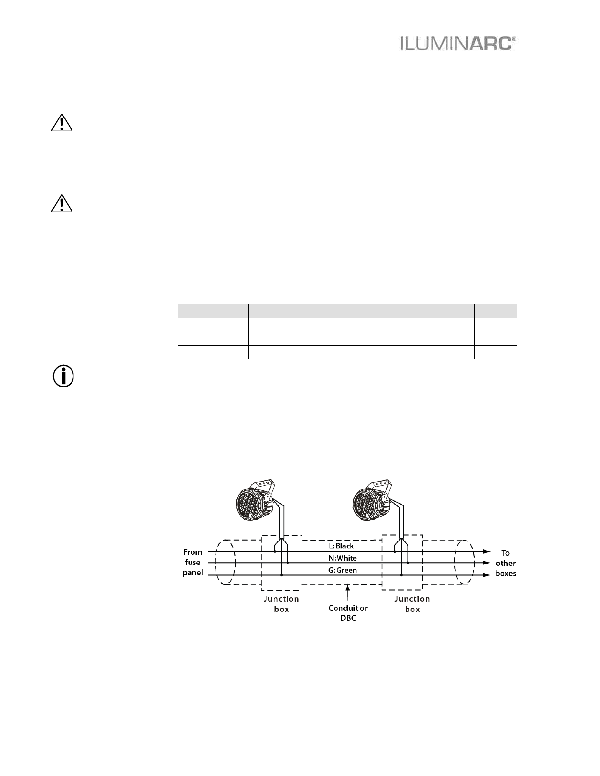
Power Wiring.......................................................................................................................6
DMX Linking................................................................................................................. 7
DMX Modes.........................................................................................................................7
Protocol Connectivity...........................................................................................................7
Master/Slave Linking.................................................................................................... 7
ID Addressing............................................................................................................... 7
Mounting....................................................................................................................... 8
Orientation...........................................................................................................................8
Rigging................................................................................................................................8
Procedure............................................................................................................................8
4. Operation.......................................................................................................9
Control Panel Description............................................................................................. 9
Control Options (RGBW Fixtures)................................................................................ 9
Programming................................................................................................................ 9
DMX Personality..................................................................................................................9
DMX Control Without ID Addressing ...................................................................................9
DMX Control With ID Addressing ........................................................................................9
Master/Slave......................................................................................................................10
Static Colors......................................................................................................................10
Auto Play...........................................................................................................................10
Edit Custom.......................................................................................................................10
Whites Setting ...................................................................................................................10
RGB to White Setting ........................................................................................................10
Password...........................................................................................................................11
Upload Customs................................................................................................................11
Reset.................................................................................................................................11
Dimmer..............................................................................................................................11
Color..................................................................................................................................11
Control Panel Description........................................................................................... 12
Control Options (SpectraWhite™ Fixtures)............................................................... 12
Programming.............................................................................................................. 12
DMX Personality................................................................................................................12
DMX Control Without ID Addressing .................................................................................12
DMX Control With ID Addressing ......................................................................................12
Master/Slave......................................................................................................................12
Static Colors......................................................................................................................13

Table of Contents
b Ilumipod 42 IP Optic Series User Manual Rev. 6
Whites Setting ...................................................................................................................13
Password...........................................................................................................................13
Upload Customs................................................................................................................13
Reset.................................................................................................................................13
Dimmer..............................................................................................................................13
Power Output.....................................................................................................................13
Menu Map (RGBW Fixtures)...................................................................................... 14
Menu Map (SpectraWhite™ Fixtures)....................................................................... 15
DMX Values RGBW Mode......................................................................................... 16
TOUR ................................................................................................................................16
TOUR (Cont.) ....................................................................................................................17
ARC1.................................................................................................................................17
ARC1+D............................................................................................................................17
ARC2.................................................................................................................................17
ARC2+D............................................................................................................................17
ARC2+S ............................................................................................................................18
HSV...................................................................................................................................18
DMX Values SpectraWhite™ Mode.......................................................................... 19
UNO ..................................................................................................................................19
STd.w ................................................................................................................................19
STd.d.................................................................................................................................19
STd.1.................................................................................................................................19
STd.2.................................................................................................................................19
5. Technical Information.................................................................................20
Fixture Maintenance................................................................................................... 20
Product Repairs.......................................................................................................... 20
Troubleshooting Guide............................................................................................... 21
Photometrics .............................................................................................................. 22
Photometrics (Cont.) .................................................................................................. 23
Photometrics (Cont.) .................................................................................................. 24
Photometrics (Cont.) .................................................................................................. 25
LED Disclaimer........................................................................................................... 26
LED Life.............................................................................................................................26
LED Binning.......................................................................................................................26
Color Rendering Index (CRI).............................................................................................26
Returns Procedure..................................................................................................... 27
Claims......................................................................................................................... 27
Contact Us.......................................................................................................27
Technical Specifications RGBW Fixtures................................................................... 28
Technical Specifications SpectraWhite™ Fixtures ................................................... 29

Introduction
Ilumipod 42 IP Optic Series User Manual Rev. 6 1
1. Introduction
This icon
indicates useful,
although non-
critical information.
This icon
indicates
important
installation or
configuration information.
Failure to comply with this
information may prevent
the fixture from
functioning correctly.
This icon
indicates critical
installation,
configuration, or operation
information. Failure to
comply with this
information may render
the fixture partially or
completely inoperative,
damage third-party
equipment, or cause harm
to the user
The term “DMX”
used throughout
this document
refers to the USITT
DMX512-A transmission
protocol.
What is Included
•One Ilumipod 42 IP Optic Series Fixture
•Warranty Card
•Quick Reference Guide
Unpacking Instructions
Immediately upon receiving a product from ILUMINARC®, carefully unpack the carton. Check
the contents of the box to ensure that all parts are present and that they are in good condition. If
any part appears damaged from shipping, or if the carton shows signs of mishandling, see the
Claims section in the Technical Information chapter.
Text Conventions
Convention
Meaning
1~512
A range of values in the text
50/60
A set of mutually exclusive values in the text
“ILUMICON UM”
The name of another publication or manual
<SET>
A button on the fixture’s control panel
Settings
A fixture function or a menu option
MENU > Settings
A sequence of menu options
1~10
A range of menu values from which to choose in a menu
Yes/No
A set of two mutually exclusive menu options in a menu
ON
A unique value to enter or select in a menu

Introduction
2 Ilumipod 42 IP Optic Series User Manual Rev. 6
There are no
user serviceable
parts inside this
product. Any reference to
servicing it you may find
from now on in this User
Manual will only apply to
properly ILUMINARC®
certified technicians. Do
not open the housing or
attempt any repairs
unless you are one of
them.
Please refer to all
applicable local
codes and
regulations for the proper
installation of this product.
Keep this manual
for future
consultation. If
you sell this product to
another user, make sure
that they also receive this
manual.
In the unlikely
event that your
Ilumipod 42 IP
Optic Series fixture may
require service, please
contact ILUMINARC®
Technical Support.
Safety Notes
Please read all the following safety notes carefully because they include important information
on how to install, use, and maintain this product safely.
Personal Safety
•Avoid direct eye exposure to the light source while the fixture is on.
•Always disconnect this product from its power source before servicing.
•Always connect this product to a grounded circuit to avoid the risk of electrocution.
•Do not touch this product’s housing when operating because it may be very hot.
Mounting and Rigging
•This product is for outdoor use and it can be submerged (IP67). However, do not
submerge it deeper than 1 m for more than (30) thirty minutes.
•CAUTION: When transferring product from extreme temperature environments, (e.g.
cold truck to warm humid ballroom) condensation may form on the internal electronics
of the product. To avoid causing a failure, allow product to fully acclimate to the
surrounding environment before connecting it to power.
•Do not allow the product to remain pointed straight down.
•When hanging this product, always secure it to a fastening device using a safety cable.
Power and Wiring
•Always make sure that you are connecting this product to the proper voltage, as per the
specifications in this manual or on the product’s sticker.
•Never connect this product to a dimmer.
•Make sure that the power input cable is not cracked, crimped, or damaged.
•Never disconnect this product by pulling or tugging on the power input cable.
Operation
•The maximum ambient temperature (Ta) is 104° F (40° C). Do not operate this product
at a higher temperature.
•In case of a serious operating problem, stop using this product immediately!

Product Description
Ilumipod 42 IP Optic Series User Manual Rev. 6 3
2. Product Description
The Ilumipod 42 IP Optic Series encompasses two types of fixtures, the Ilumipod 42 IP Optic
RGBW and Ilumipod 42 IP Optic VW. These fixtures are available in 15 degree and 30 degree
optics.
Common Features
•316 Stainless Steel hardware for corrosive environments
•Integrated command™ LCD
•Integrated cooling enhancement™
•42 - 1 watt LEDs
•UV resistant Gray or White powder coat
•Humidity controlling gore valve
•Heavy duty single piece yoke
•Tamper-resistant lockable vertical adjustment screws
•IP67 rated
RGBW Features
•3, 4, 5, 6, or 11-channel RGBW LED wash light with ID addressing
•Operating modes:
3-channel: HSV control
3-channel: RGB control
4-channel: RGB, dimmer
4-channel: RGBW control
5-channel: RGBW, dimmer
6-channel: RGBW, dimmer, strobe
11-channel: RGBW, dimmer, macros, strobe, auto/custom, auto speed, ID
addressing, dimmer curve
•Static color mixing with or without a DMX controller
•Five distinct dimmer curves
•Color temperature presets (3,200 K ~ 10,000 K)
•Optical systems: 15°and 30°
SpectraWhite™ Features
•1, 2, 3 or 6-channel DMX LED wash light with ID addressing
•Operating modes:
1-channel: Dimmer
2-channel: Color temperature macros
2-channel: Warm white, cool white control
3-channel: Dimmer, warm white, cool white, color
6-channel: Dimmer, warm white, cool white, color, temperature macros, strobe, ID
addressing
•Static color temperature control with or without a DMX controller
•VW SpectraWhite™ mixing with or without DMX controller via Integrated command™
LCD display
•2,800 K and 7,000 K LEDs

Product Description
4 Ilumipod 42 IP Optic Series User Manual Rev. 6
Product Overview
Front View
Rear View
316 Stainless
Steel Hardware
Tempered Glass
Lens Cover
Tamper
Resistant
Adjustment Bolt
Cast Aluminum
Housing
Safety Cable
Loop
Humidity
Control Valve
(under bracket)
Power In
DMX In/Out
(under bracket)
13 mm
Mounting Holes
Heavy Duty
Mounting
Bracket
LED Display
(under cover)

Product Description
Ilumipod 42 IP Optic Series User Manual Rev. 6 5
Product Dimensions

Installation
6 Ilumipod 42 IP Optic Series User Manual Rev. 6
3. Installation
Always connect
the Ilumipod 42
IP Optic Series to
a protected circuit with an
appropriate electrical
ground to avoid the risk of
electrocution or fire.
Never connect
the Ilumipod 42
IP Optic Series to
a rheostat (variable
resistor) or dimmer circuit,
even if the rheostat or
dimmer channel serves
only as a 0 to 100%
switch.
Please refer to all
applicable local
codes and
regulations for the proper
installation of this product.
AC Power
The Ilumipod 42 IP Optic Series has an auto-ranging power supply that can work with an input
voltage range of 100~240 VAC, 50/60 Hz.
Make sure that you are connecting this product to the proper voltage, as per the specifications in
this guide, the product’s QRG, or on the product’s sticker.
Power Consumption
To determine the power requirements for the Ilumipod 42 IP Optic Series, see the label
affixed to the side of the fixture or refer to the corresponding specifications chart in the
Technical Information chapter of this manual.
The listed current rating indicates the maximum current draw during normal operation.
AC Plug
The Ilumipod 42 IP Optic Series comes with an un-terminated power input cord for
hardwiring during installation. Use the table/illustration below to wire a plug.
Connection Wire (US) Screw Color (US) Wire (Europe) IP67 Pin
AC Live
Black
Yellow or Brass
Brown
1
AC Neutral
White
Silver or Gray
Blue
2
AC Ground
Green/Yellow
Green
Green/Yellow
3
Power Wiring
You can connect the bare-ended IP67 rated AC power cable from the fixture to an IP67
rated power connector.
You may also use IP67 rated junction boxes for surface installations or direct buried cable
(DBC)for buried installations.
If using junction boxes, make sure to use IP67 rated conduit for surface installations or
direct buried cable (DBC) for buried installations. You could also use direct buried cable
(DBC) to link the junction boxes. See below for a wiring illustration.

Installation
Ilumipod 42 IP Optic Series User Manual Rev. 6 7
The Operation
chapter of this
manual provides
detailed
instructions on how to
configure the Master and
Slave units.
DMX Linking
You may link the Ilumipod 42 IP Optic Series to a DMX controller using a standard DMX
serial connection. If using other DMX compatible fixtures with the Ilumipod 42 IP Optic Series,
it is possible to control them individually with a single DMX controller.
It is also possible to run several DMX compatible fixtures synchronized without a DMX
controller in a master/slave operating mode. The Ilumipod 42 IP Optic Series does support the
master/slave mode.
If you are not familiar with the DMX standard, or if you need information about the DMX
cables needed to link the Ilumipod 42 IP Optic Series to a DMX controller, you may download
the “DMX Primer” document from the ILUMINARC® Web site.
DMX Modes
The Ilumipod 42 IP Optic Series uses the standard DMX data connection for all its DMX
personalities whether they are RGBW or VW versions. Refer to the Introduction chapter for
a brief description of these modes and the Operation chapter to learn how to configure the
Ilumipod 42 IP Optic Series to work in these modes. The DMX Values section will give you
detailed information regarding the above-mentioned DMX modes.
Protocol Connectivity
The Ilumipod 42 IP Optic Series uses USITT DMX 512 Protocol. The procedure below
illustrates the recommended connection method.
Master/Slave Linking
The Master/Slave mode allows a Ilumipod 42 IP Optic Series fixture (the master) running a
preconfigured program to control several other Ilumipod 42 IP Optic Series fixtures (the slaves)
without requiring a DMX controller. In this mode, all the slave fixtures will operate in unison
with the master fixture.
When in Master/Slave mode, the Ilumipod 42 IP Optic Series units link to each other using the
standard DMX connection.
ID Addressing
The Ilumipod 42 IP Optic Series uses the ID Addressing feature to increase the number of
addressable fixtures in the same DMX universe when in the TOUR personality. Refer to the
Operation chapter in this manual to learn in detail how to configure the Ilumipod 42 IP Optic
Series fixtures when using ID Addressing.

Installation
8 Ilumipod 42 IP Optic Series User Manual Rev. 6
Make sure to
mount this fixture
away from any
flammable material as
indicated in the Safety
Notes.
Mounting
Before mounting this fixture, read and follow the safety recommendations indicated in the
Safety Notes section (page 2 of this manual).
Orientation
Always mount this fixture in any safe position while making sure that there is adequate
room around it for ventilation, configuration, and maintenance.
Rigging
The Ilumipod 42 IP Optic Series consists of the fixture body and a single heavy duty
mounting bracket with 13mm screw holes. ILUMINARC®recommends following the
general guidelines below when mounting the Ilumipod 42 IP Optic Series.
•When selecting an installation location, consider ease of access to the fixture for
operation, programming adjustments, and routine maintenance.
•Do not allow the product to remain pointed straight down.
•Make sure that the location where you are mounting the fixture can support its weight.
Please see the Technical Specifications section of this manual for the weight requirement
of this fixture.
Procedure
The Ilumipod 42 IP Optic Series comes with a single heavy duty mounting bracket to which
you can attach “C” or “O” clamps. You must supply your own “C” or “O” clamps and make
sure that they are capable of supporting the weight of this fixture.
C Clamp
(not included)
Secure safety cable
through loop on rear of
fixture

Operation
Ilumipod 42 IP Optic Series User Manual Rev. 6 9
4. Operation
When
programming live
performances as
well as cues that need to
trigger on demand or on a
time line, program no
more than 10 fixtures on
ID addressing per DMX
channel. This is to remain
within a one-second
execution time.
If ID Addressing
is active in a
fixture’s control
panel, unintended results
may occur if DMX channel
11’s value is higher than
“0” when in TOUR. Make
sure to disable ID
addressing and to set
DMX channel 11 to “0” if
using TOUR.
Control Panel Description
Button Function
<MENU>
Exits from the current menu or function.
<ENTER>
Enables the displayed menu or sets the selected
value to the current function.
<UP>
Navigates upwards through the menu list and
increases the numeric value when in a function.
<DOWN>
Navigates downwards through the menu list and
decreases the numeric value when in a function.
Control Options (RGBW Fixtures)
You can set the Ilumipod 42 IP Optic RGBW start address in the 001~512 DMX range. This
allows for the control of up to 46 fixtures in the 11-channel TOUR personality. In addition, the
ID address system allows you to assign up to 66 fixtures within the same DMX address, thus
multiplying the number of fixtures you can control within a single universe. You can access the
fixture’s ID address system from channel 11 when in the TOUR personality.
Programming
Carry out all the programming procedures indicated below from the control panel. Refer to the
Menu Map in page 14 to learn how the menu options relate to each other.
Use <ENTER> and <MENU> to change levels in the Menu Map. This is equivalent to move
right and left respectively. Use <UP> and <DOWN> to move vertically within the Menu Map
options.
DMX Personality
1. Go to MENU > PERS and select any DMX personality.
2. Make sure to rearrange the DMX addresses of all fixtures in the current DMX
universe to avoid address overlapping.
DMX Control Without ID Addressing
1. Go to MENU > RUN and select dMx.
2. Go to MENU > dMx and select a starting DMX address (001~512).
3. Go to MENU > SET > Id and select OFF.
DMX Control With ID Addressing
1. Repeat steps 1and 2from DMX Control Without ID Addressing.
2. Go to MENU > SET > Id and select ON.
3. Go to MENU > Id and select an ID address (1~66).
4. When in TOUR, channel 11 controls ID addressing.

Operation
10 Ilumipod 42 IP Optic Series User Manual Rev. 6
The master
fixture becomes
Master when in
AUTO mode.
AUTO 01~10
are fully
configured
programs and
you cannot modify them.
However, you can edit PR
01~10 programs (see Edit
Custom).
Master/Slave
On the Master unit:
1. Go to MENU > RUN and select dMx.
2. Go to MENU > AUTO and select any Auto or Custom program. You may also go
to MENU > STAT and manually set the color values (see Static Colors).
On each of the Slave units:
3. Go to MENU > RUN and select SLAV.
The slave fixtures will follow the program played by the Master.
Static Colors
1. Go to MENU > STAT.
2. Select a color or effect (R, G, b, w, or ST).
3. Select a color value (000~255) or a strobe frequency (0~20).
Auto Play
1. Go to MENU > AUTO.
2. Select a program (AT 01~10 or PR 01~10).
Edit Custom
1. Go to MENU > EdIT.
2. Select a program (PR 01~10).
3. Select a scene (SC 01~30).
4. Select a color, strobe, or timers (R, G, b, w, Sb, T, or F).
5. Configure the color value (0~255).
6. Repeat steps 4 and 5 for the other colors.
7. Configure the strobe frequency (0~20).
8. Configure the Step and Fade timers (0~255).
9. Repeat steps 4 to 8 for the other scenes.
Whites Setting
1. Go to MENU > CAL1.
2. Select a white color (wT 1~11).
3. Select an RGB color (R, G, b, or w).
4. Configure the color value (0~255).
5. Repeat steps 3 and 4 for the other RGBW colors to obtain a white color.
6. Repeat steps 2 to 5 for the other white colors.
RGB to White Setting
1. Go to MENU > CAL2 > RGbw.
2. Select an RGB color (R, G, or b).
3. Configure the color value (0~255).
4. Repeat steps 2 and 3 for the other RGB colors to obtain a white color.

Operation
Ilumipod 42 IP Optic Series User Manual Rev. 6 11
The Password is
fixed by default
DIM1 is the
fastest dimmer
curve and DIM4
is the slowest.
Password
When KEYLOCK is active, the fixture will ask you to enter the password (<UP>,
<DOWN>, <UP> and <DOWN>) after 30 seconds of control panel inactivity or upon
power up.
1. Go to MENU > KEY.
2. Select a setting (ON/OFF).
Upload Customs
1. Set all fixtures that are going to receive the upload to SLAV operation.
2. Disconnect the fixtures from the DMX controller.
3. On the fixture whose custom programs you are going to copy, got to MENU >
SET and select UPLd.
4. Enter the password and press <ENTER> for the upload to start.
Procedure:
a) When the transfer starts, all the fixtures will display yellow.
b) If the upload is successful, all the fixtures will show green.
c) If the upload is unsuccessful, the master and/or slave fixtures will show red.
Reset
1. Go to MENU > SET > REST.
2. Enter the password and press <ENTER>.
Dimmer
1. Go to MENU > SET > dIM.
2. Select a dimmer curve (OFF or dIM1~4).
Procedure:
OFF = Linear RGBW and Master Dimmer.
DIM1~4 = Non-linear RGBW and Master Dimmer.
Color
1. Go to MENU > SET > COLO.
2. Select the color method (OFF, RGbw, UC).
Procedure:
OFF
When the RGB faders are all set to “255”, the output is maximum.
RGbw
When the RGB faders are all set to “255”, the output is the selected White color (see RGB to
White Setting section).
UC
When the RGB faders are all set to “255”, the output matches the same color output of
previous versions of this fixture.

Operation
12 Ilumipod 42 IP Optic Series User Manual Rev. 6
When
programming live
performances as
well as cues that need to
trigger on demand or on a
time line, program no
more than 10 fixtures on
ID addressing per DMX
channel. This is to remain
within a one-second
execution time.
If ID Addressing
is active in a
fixture’s control
panel, unintended results
may occur if DMX channel
6’s value is higher than
“0” when in STd2. Make
sure to disable ID
addressing and to set
DMX channel 6 to “0” if
using STd2.
The master
fixture
becomes
Master when in STAT
mode.
Control Panel Description
Button Function
<MENU>
Exits from the current menu or function
<ENTER>
Enables the currently displayed menu or sets the
currently selected value in to the current function
<UP>
Navigates upwards through the menu list and
increases the numeric value when in a function
<DOWN>
Navigates downwards through the menu list and
decreases the numeric value when in a function
Control Options (SpectraWhite™ Fixtures)
You can set the Ilumipod 42 IP Optic VW start address in the 001~512 DMX range. This
allows for the control of up to 85 fixtures in the 6-channel STd2 personality. In addition, the ID
address system allows you to assign up to 66 fixtures within the same DMX address, thus
multiplying the number of fixtures you can control within a single universe. You can access the
fixture’s ID address system from channel 6 when in the STd2 personality.
Programming
Carry out all the programming procedures indicated below from the control panel. Refer to the
Menu Map in page 15 to learn how the menu options relate to each other.
Use <ENTER> and <MENU> to change levels in the Menu Map. This is equivalent to move
right and left respectively. Use <UP> and <DOWN> to move vertically within the Menu Map
options.
DMX Personality
1. Go to MENU > PERS and select any DMX personality.
2. Make sure to rearrange the DMX addresses of all fixtures in the current DMX
universe to avoid address overlapping.
DMX Control Without ID Addressing
1. Go to MENU > RUN and select dMx.
2. Go to MENU > dMx and select a starting DMX address (001~512).
3. Go to MENU > SET > Id and select OFF.
DMX Control With ID Addressing
1. Repeat steps 1and 2from DMX Control Without ID Addressing.
2. Go to MENU > SET > Id and select ON.
3. Go to MENU > Id and select an ID address (1~66).
4. When in STd2, channel 6 controls ID addressing.
Master/Slave
On the Master unit:
1. Go to MENU > RUN and select dMx.
2. Go to MENU > STAT and manually set the color values (see Static Colors).
On each of the Slave units:
3. Go to MENU > RUN and select SLAV.
The slave fixtures will follow the program played by the Master.

Operation
Ilumipod 42 IP Optic Series User Manual Rev. 6 13
The Password is
fixed by default
DIM1 is the
fastest dimmer
curve and DIM4
is the slowest.
Static Colors
1. Go to MENU > STAT.
2. Select a color or effect (w, C, or ST).
3. Select a color value (000~255) or a strobe frequency (0~20).
Whites Setting
1. Go to MENU > CAL1.
2. Select a white color (wT 1~5).
3. Select a cool or warm color (C or w).
4. Configure the color value (0~255).
5. Repeat steps 3 and 4 for the other cool or warm colors to obtain a balanced white
color.
6. Repeat steps 2 to 5 for the other white colors.
Password
When KEYLOCK is active, the fixture will ask you to enter the password (<UP>,
<DOWN>, <UP> and <DOWN>) after 30 seconds of control panel inactivity or upon
power up.
1. Go to MENU > KEY.
2. Select a setting (ON/OFF).
Upload Customs
1. Set all fixtures that are going to receive the upload to SLAV operation.
2. Disconnect the fixtures from the DMX controller.
3. On the fixture whose custom programs you are going to copy, got to MENU >
SET and select UPLd.
4. Enter the password and press <ENTER> for the upload to start.
Procedure:
a) When the transfer starts, all the fixtures will display yellow.
b) If the upload is successful, all the fixtures will show green.
c) If the upload is unsuccessful, the master and/or slave fixtures will show red.
Reset
1. Go to MENU > SET > REST.
2. Enter the password and press <ENTER>.
Dimmer
1. Go to MENU > SET > dIM.
2. Select a dimmer curve (OFF or dIM1~4).
Procedure:
OFF = Linear RGBW and Master Dimmer.
DIM1~4 = Non-linear RGBW and Master Dimmer.
Power Output
When HIGH is selected the fixture’s power consumption increases from 90 W to 150 W.
This will increase the output of the fixture for a limited time only. The fixture will
automatically adjust output to prevent overheating.
1. Go to MENU > SET > POw.
2. Select a power setting (NORM or HIGH).

Operation
14 Ilumipod 42 IP Optic Series User Manual Rev. 6
Menu Map (RGBW Fixtures)
1
st
Level Programming Levels Description
STAT
R (red)
000~255 Combines red, green, blue, and white to form a
custom color
G (green)
b (blue)
w (white)
ST (strobe)
00~20
Strobe frequency (0~20 Hz)
AUTO
AT.1~10
Selects any of the 10 auto programs
PR.1~10
Selects any of the 10 custom (editable) programs
RUN
dMX
Operates with a DMX controller
SLAV
Operates with a master fixture
dMX
d.001~512
Sets the DMX starting address
PERS
TOUR
11 channels (RGBW, D, S, CM, A, AS, DS, ID)
ARC.1
3 channels (RGB)
AR1.D
4 channels (RGB, D)
ARC.2
4 channels (RGBW)
AR2.d
5 channels (RGBW, D)
AR2.S
6 channels (RGBW, D, S)
HSV
3 channels (hue, saturation, value)
Id
Id.01~66
Assigns an ID address to the fixture
EDIT PR.
01~10 SC.
01~30
R (red)
000~255 Combines red, green, blue, and white to form a
custom color
G (green)
b (blue)
w (white)
Sb (strobe)
00~20
Strobe frequency (0~20 Hz)
T (time)
000~255
Step duration
F (fade)
Fade duration
SET
UPLd (upload)
<Password>
Uploads custom programs to another fixture
REST (reset)
Resets the fixture to factory settings
Id (ID addressing)
ON/OFF
Turns ID addressing on or off
COLO
(color calibration)
OFF
Max output when RGBW faders are at 255
RGbw (RGB to white)
Pre-set output when RGBW faders are at 255
UC (Universal Color)
Output matches that of older fixtures
dIM
(dimmer speed)
OFF
Makes dimmer curve linear
dIM1~4
Changes the dimmer curve (fast óslow)
CAL1 wT.01~11
(White
temperature)
R (red)
000~255 Modifies the white temperature used in the
macros channel (TOUR, channel 6)
G (green)
b (blue)
w (white)
CAL2 RGbw
(RGB to white)
R (red)
000~255 Modifies the white color used when SET >
COLOR > RGbw is active
G (green)
b (blue)
KEY
ON/OFF
Turns the password on or off

Operation
Ilumipod 42 IP Optic Series User Manual Rev. 6 15
Menu Map (SpectraWhite™ Fixtures)
1st Level Programming Levels Description
STAT
w (warm white) 000~255 Warm White and Cool White generate a white
temperature (0~100%)
C (cool white)
ST (strobe) 00~20 Strobe frequency (0~20 Hz)
RUN dMX Operates with a DMX controller
SLAV Operates with a master fixture
dMX d.001~512 Sets the DMX starting address
PERS
STd.w 2 channels (WW & CW)
STd.d 3 channels (WW & CW, D)
STd.1 2 channels (WM, D)
STd.2
6 channels (WW, CW, WM, S, D, ID)
UNO 1-channel (dimmer)
Id Id.01~66 Assigns an ID address to the fixture
SET
UPLd (upload) <Password> Uploads custom program to another fixture
REST (reset) Resets the fixture to the default, factory settings
Id
(ID addressing)
ON/OFF Turns ID addressing on or off
POw (power) HIGH High Output (Power consumption: 150 W)
NORM Normal Output (Power consumption: 90 W)
dIM
(dimmer speed) Off Makes dimmer curve linear
dIM1~4 Changes the dimmer curve (fast óslow)
CAL1 wT.01~05
(white
temperature)
w
(warm white)
000~255 Modifies the white temperature used in the white
macros channel (STd.2, channel 4)
C
(cool white)
KEY ON/OFF Turns the password on or off

Operation
16 Ilumipod 42 IP Optic Series User Manual Rev. 6
DMX Values RGBW Mode
TOUR
Channel Function Value Percent/Setting
1
Dimmer
000 ó255
0~100%
2
Red
000 ó255
0~100%
Step Time
When running a custom program
3
Green
000 ó255
0~100%
Fade Time
When running a custom program
4
Blue
000 ó255
0~100%
5
White
000 ó255
0~100%
6 Color Macro + White Balance
000 ó010
011 ó030
031 ó050
051 ó070
071 ó090
091 ó110
111 ó130
131 ó150
151 ó170
171 ó200
201 ó205
206 ó210
211 ó215
216 ó220
221 ó225
226 ó230
231 ó235
236 ó240
241 ó245
246 ó250
251 ó255
No Function
R: 100% G: Up B: 0%
R: Down G: 100% B: 0%
R: 0% G: 100% B: Up
R: 0% G: Down B: 100%
R: Up G: 0% B: 100%
R: 100% G: 0% B: Down
R: 100% G: Up B: Up
R: Down G: Down B: 100%
R, G, B, & W: 100%
White 1: 3,200 K
White 2: 3,400 K
White 3: 4,200 K
White 4: 4,900 K
White 5: 5,600 K
White 6: 5,900 K
White 7: 6,500 K
White 8: 7,200 K
White 9: 8,000 K
White 10: 8,500 K
White 11: 10,000 K
7 Strobe
000 ó010
011
ó
255
No Function
0~20 Hz
8 Program
000 ó020
021 ó030
031 ó040
041 ó050
051 ó060
061 ó070
071 ó080
081 ó090
091 ó100
101 ó110
111 ó120
121 ó130
131 ó140
141 ó150
151 ó160
161 ó170
171 ó180
181 ó190
191 ó200
201 ó210
211 ó220
221 ó255
No Function
Auto 1
Auto 2
Auto 3
Auto 4
Auto 5
Auto 6
Auto 7
Auto 8
Auto 9
Auto 10
Custom 1
Custom 2
Custom 3
Custom 4
Custom 5
Custom 6
Custom 7
Custom 8
Custom 9
Custom 10
No Function
9
Auto Speed Adjust
000 ó255
0~100% (only when running auto programs)
10 Dimmer Speed
000 ó009
010 ó029
030 ó069
070 ó129
130 ó189
190
ó
255
Preset dimmer speed
Linear dimmer
Dimming curve 1 (fastest)
Dimming curve 2
Dimming curve 3
Dimming curve 4 (slowest)
Continued on next page
Other manuals for Ilumipod 42 IP Series
1
Table of contents
Other Iluminarc Dj Equipment manuals

Iluminarc
Iluminarc LOGIC CVS User manual

Iluminarc
Iluminarc ILUMIPOD SL User manual

Iluminarc
Iluminarc Ilumipod 48 IP Optic RGBW User manual

Iluminarc
Iluminarc LOGIC AR111 Downlight S User manual

Iluminarc
Iluminarc LOGIC MR16 User manual

Iluminarc
Iluminarc LOGIC AR111 DN M User manual

Iluminarc
Iluminarc Ilumiline Logic 24 Optic RGB User manual

Iluminarc
Iluminarc LOGIC Wall Panel 16-Port User manual

Iluminarc
Iluminarc Colorist Panel 36Qa User manual

Iluminarc
Iluminarc Ilumiline 36 IP Optic RGB User manual